
Related Manuals for SystemAir VH07


Summary of Contents for SystemAir VH07
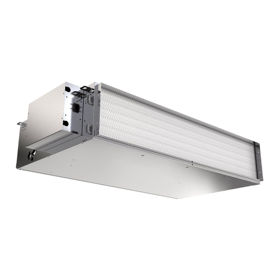
- Page 1 Installation and maintenance manual 07 / 27 High Static Pressure Ductable Fan Coil Unit 5.3 â 26.9kW 4.1 â 22.6kW 800 â 4650m...
- Page 3 INSTALLATION INSTRUCTION English NOTICE D’INSTALLATION Français INSTALLATIONSHANDBUCH Deutsch ISTRUZIONI INSTALLAZIONE Italiano INSTRUCCIONES DE INSTALACIÓN Español...
-
Page 4: Table Of Contents
2 VH CONTENTS 1. GENERAL RECOMMENDATIONS ................................ 3 1.1. SAFETY DIRECTIONS ............................................3 1.2. WARNING ................................................. 3 2. INSPECTION AND STORAGE ................................4 3. WARRANTY ...................................... 4 4. TECHNICAL SPECIFICATIONS ................................4 4.1. OPERATING LIMITS ............................................4 4.2. ELECTRICAL SPECIFICATIONS FOR STANDARD MOTORS ................................5 4.3. -
Page 5: General Recommendations
POWER SUPPLY MUST BE SWITCHED OFF BEFORE STARTING WORK IN THE ELECTRIC CONTROL BOX 1. GENERAL RECOMMENDATIONS The purpose of this Manual is to provide users with instructions for installing, commissioning, using and maintaining the units. It does not contain the complete description of all the maintenance operations guaranteeing the unit’s long life and reliability. -
Page 6: Inspection And Storage
4 VH 2. INSPECTION AND STORAGE At the time of receiving the equipment carefully cross check all the elements against the shipping documents in order to ensure that all the crates and boxes have been received. Inspect all the units for any visible or hidden damage. -
Page 7: Electrical Specifications For Standard Motors
4.2. ELECTRICAL SPECIFICATIONS FOR STANDARD MOTORS Motors - 230 V / 1 ph / 50 Hz / 60 Hz VH07 VH15 VH18 Current Power Current Power Current Power Unit size absorbed absorbed absorbed absorbed absorbed absorbed (A) * (w)* (A) *... -
Page 8: Handling
Unit size Weight Circular / circular version Rectangular / rectangular Rectangular / rectangular (including new air flow version version + new air flow plenum) plenum VH07 VH15 VH18 VH21 VH24 VH27 Weight in functioning order, without valve 6. INSTALLATION Caution The unit is not designed to withstand weights or stresses from adjacent equipment, pipe work or constructions. -
Page 9: Unit Location
5. Lock the unit in its final location and level it off with a spirit level in order to guarantee correct operation and condensate evacuation. 6. The unit must be installed so that the water drains towards the evacuation connection. Mounting lugs Unit size (mm) (mm) (mm) (mm) VH07 1240 VH15 1420 VH18 1420 TOP VIEW VH21 1420... -
Page 10: Hydraulic Connections
8 VH 7. HYDRAULIC CONNECTIONS Caution The fan-coil units may contain a small amount of oil incompatible with plastic polyethylene piping (PER/HTA/PVC). The coil should be rinsed out before use to avoid any problem. It is the installer’s responsibility to contact their pipe supplier and take into account the general instructions for the use of plastic pipes (PER/HTA/PVC). -
Page 11: Coil Water Volume
For 4-pipe fan coil units (VH07) with a hydraulic connection left side, the hot coil is located after the cold coil, in relation to the direction of the air.However, for units (VH07) on which a straight hydraulic connection is chosen, the hot battery is located before the cold battery. For 4 tube fan-convector units (VH15/VH18/ VH21/VH24/VH27), the hot battery is always located after the cold battery from the airflow point of view. -
Page 12: Condensate Drain Connection
10 VH 7.4. CONDENSATE DRAIN CONNECTION A condensate tray is supplied with a 5/8" exterior diameter copper drain hole. Ensure that the condensed water will drain properly from the tray, which must be connected to the main evacuation pipe. The evacuation pipe must be installed with a downhill angle. Check that the evacuation pipe work has a siphon which must be made in accordance with the illustration below. -
Page 13: Water Quality
7.6. WATER QUALITY The water must be analyzed; the hydraulic network system installed must include all elements necessary for water treatment: filters, additives, intermediate exchangers, drain valves, vents, check valves, etc., according to the results of the analysis. Using improperly treated or non treated water in the VH may cause scaling, erosion, corrosion or algae or sludge deposits in the exchangers. -
Page 14: Aeraulic Connections
12 VH 8. AERAULIC CONNECTIONS Only the supply air plenum is insulated. The return air plenum is fitted with a pre-cut inlet for fresh air intake: Ø100mm or Ø125mm (VH07) ² Ø160mm (VH15 - VH18 - VH21) ² Ø200mm (VH24 - VH27) ²... -
Page 15: Electrical Connections
9.1. WIRING DIAGRAM AND LEGEND SEE APPENDIX SE3931 models VH07/VH15/VH18/VH21/VH24/VH27 230V 50Hz/60Hz +/- 10% SE3932 models VH07 + Aquanet 230V 50Hz/60Hz +/- 10% SE3933 models VH15/VH18/VH21/VH24/VH27 + Aquanet 230V 50Hz/60Hz +/- 10% 9.2. POWER SUPPLY All fan coil units are designed for operation under 230 volts, single phase, 50 or 60 cycles . -
Page 16: Regulation
14 VH 9.4. REGULATION As standard, the units are supplied without regulation equipment. However, certain control devices (fan speed selector, remote thermostat, etc.) can be supplied according to request. In all events, these regulation devices are only intended to control a single unit. Caution Do not connect several units to a single ventilation speed selector or regulation thermostat without using auxiliary relays. -
Page 17: Commissioning
10. COMMISSIONING 10.1. PRE-START CHECK LIST 10.1.1. ELECTRICAL CHECK 1. Electrical installation has been carried out according to unit wiring diagram and the Supply Authority Regulations. 2. Size fuses or circuit breaker has been installed at the main switchboard. 3. Supply voltages as specified on unit wiring diagram. 4. -
Page 18: Operation
16 VH 11. OPERATION The unit operates in different ways, depending of the control options that have been installed: AQUANET TRM-FA ² ² AQUASIMP TAE 20 ² ² SEE APPENDIX 11.1. AQUANET OR AQUASIMP SEE SPECIFIC MANUAL AQUANET AQUASIMP 11.2. ROOM THERMOSTAT TRM-FA 11.2.1. -
Page 19: Electrical Connections
11.2.4. ELECTRICAL CONNECTIONS Connection of the thermostat TRM-FA. Connections should be made according to the diagram (SEE APPENDIX). Max. cross-sectional area of wires : 2,5 mm 11.2.5. WALL MOUNTING Remove the thermostat control knob, the screw and the cover. ² On a flat surface, mount the control panel using plugs and screws. -
Page 20: Tae20 Room Thermostat
18 VH 11.3. TAE20 ROOM THERMOSTAT 11.3.1. FIELDS OF APPLICATION Regulating ambient temperature in rooms heated or cooled. ² Opening and closing the valve. ² Cutting in and out the electric heating. ² Controlling the three fan speed. ² 11.3.2. DESCRIPTION The unit comprises two parts: A plastic case, housing the electronics, the controls and an internal ambience sensor. -
Page 21: Operating Check List
11.4. OPERATING CHECK LIST 11.4.1. GENERAL 1. Before initial start up, be sure that the fan wheel is rotating free on it shaft. 2. Make sure that the filter is correctly positionned on its bracket. 3. Ensure that all hydraulic connections are tightened correctly. 4. -
Page 22: Maintenance
20 VH 13. MAINTENANCE Caution The user is responsible for ensuring that the unit is in perfect working order and that the technical installation and minimum annual maintenance operations have been performed by a qualified technician in accordance with the procedures described in the present manual. 13.1. -
Page 23: Condensate Tray
13.4. CONDENSATE TRAY The condensate tray must be checked regularly to ensure that the evacuation pipe is not blocked. If required, it can be cleaned and washed with water. To remove the condensate tray : 1. Remove the filter access panel (B). 2. -
Page 24: Servicing Checklist
22 VH 13.9. SERVICING CHECKLIST 13.9.1. CASING 1. Clean the outer panels. 2. Remove the panels. 3. Check that the insulation is not damaged. Repair as required. 13.9.2. CONDENSATE DRAIN PAN 1. Check that the drainage orifices, conduits and siphon are not blocked. 2. - Page 25 APPENDIX / ANNEXE / ANLAGE / ALLEGATO / ANEXO APPENDIX ANNEXE ANLAGE ALLEGATO ANEXO...
- Page 26 APPENDIX DIMENSIONS ................III WIRING DIAGRAM ..............VIII VH07 ........................III VH07 / VH15 / VH18 / VH21 / VH24 / VH27 ..........IX VH15 ........................IV VH07 + AQUANET .....................X VH18 ........................V VH15 / VH18 / VH21 / VH24 / VH27 + AQUANET ........XI VH21 ........................VI...
-
Page 27: Dimensions
APPENDIX / ANNEXE / ANLAGE / ALLEGATO / ANEXO DIMENSIONS DIMENSIONS ABMESSUNGEN DIMENSIONI DIMENSIONES 255.5 67.5 VH07 3 x Ø200 1182 = Ø250 392.5 207.5 392.5 Ø 100 Ø 125 117.5 117.5 117.5 117.5... -
Page 28: Vh15
APPENDIX / ANNEXE / ANLAGE / ALLEGATO / ANEXO VH15 253.5 1360 Ø 160 52.3 117.3 117.3 117.3 117.3 52.3 IV VH... - Page 29 APPENDIX / ANNEXE / ANLAGE / ALLEGATO / ANEXO VH18 253.5 1360 Ø 160 95.6 52.3 99.8 138.9 138.9 138.9 138.9 52.3 95.6 99.8...
-
Page 30: Vh21
APPENDIX / ANNEXE / ANLAGE / ALLEGATO / ANEXO VH21 253.5 1360 Ø 160 95.6 138.9 52.3 99.8 138.9 138.9 138.9 52.3 99.8 95.6 VI VH... -
Page 31: Vh24 / Vh27
APPENDIX / ANNEXE / ANLAGE / ALLEGATO / ANEXO VH24 / VH27 1480 Ø 200 88.1 88.1 44.8 85.5 85.5 131.4 131.4 44.8 88.1 88.1 85.5 85.5... -
Page 32: Wiring Diagram
APPENDIX / ANNEXE / ANLAGE / ALLEGATO / ANEXO WIRING DIAGRAM SCHEMAS ELECTRIQUES STROMLAUFPLANS SCHEMA ELETRICO ESQUEMA ELECTRICO TAKE CARE! These wiring diagrams are correct at the time of publication. Manufacturing changes can lead to modifications. Always refer to the diagram supplied with the product. ATTENTION Ces schémas sont corrects au moment de la publication. -
Page 33: Vh07 / Vh15 / Vh18 / Vh21 / Vh24 / Vh27
APPENDIX / ANNEXE / ANLAGE / ALLEGATO / ANEXO VH07 / VH15 / VH18 / VH21 / VH24 / VH27... -
Page 34: Vh07 + Aquanet
APPENDIX / ANNEXE / ANLAGE / ALLEGATO / ANEXO VH07 + AQUANET X VH... -
Page 35: Vh15 / Vh18 / Vh21 / Vh24 / Vh27 + Aquanet
APPENDIX / ANNEXE / ANLAGE / ALLEGATO / ANEXO VH15 / VH18 / VH21 / VH24 / VH27 + AQUANET... - Page 36 APPENDIX / ANNEXE / ANLAGE / ALLEGATO / ANEXO 2-PIPE COILS 4-PIPE COILS COOLING HEATING LOW SPEED MEDIUM SPEED HIGH SPEED BATTERIES BATTERIES FROID CHAUD PETITE VITESSE VITESSE MOYENNE GRANDE VITESSE 2 TUBES 4 TUBES 2 LEITER 4 LEITER KLEINE MITTLERE HOHE KÜHLUNG...
- Page 37 APPENDIX / ANNEXE / ANLAGE / ALLEGATO / ANEXO TAE20 TAE20 TAE20 TRM-VP XIII...
- Page 38 APPENDIX / ANNEXE / ANLAGE / ALLEGATO / ANEXO TRM-VP TRM-VP TRM-VP TRM-VP XIV VH...
- Page 39 APPENDIX / ANNEXE / ANLAGE / ALLEGATO / ANEXO TRM-FA TRM-FA TRM-FA TRM-FA...
- Page 40 APPENDIX / ANNEXE / ANLAGE / ALLEGATO / ANEXO TRM-FA 2T + 2T + TRM-FA AQUASIMP AQUASIMP XVI VH...
- Page 41 APPENDIX / ANNEXE / ANLAGE / ALLEGATO / ANEXO AQUASIMP AQUASIMP 2T + 2T + AQUASIMP AQUASIMP XVII...
- Page 42 APPENDIX / ANNEXE / ANLAGE / ALLEGATO / ANEXO XVIII VH...
- Page 44 As part of our ongoing product improvement programme, our products are subject to change without prior notice. Non contractual photos. Systemair AC SAS Route de Verneuil 27570 Tillières-sur-Avre FRANCE & : +33 (0)2 32 60 61 00 6 : +33 (0)2 32 32 55 13...
Need help?
Do you have a question about the VH07 and is the answer not in the manual?
Questions and answers