Table of Contents
Advertisement
Advertisement
Table of Contents

Related Manuals for Furuno FAX-408


Summary of Contents for Furuno FAX-408
- Page 1 OPERATOR'S MANUAL FACSIMILE RECEIVER FAX-408 MODEL www.furuno.co.jp...
- Page 2 Nishinomiya, 662-8580, JAPAN Telephone : +81-(0)798-65-2111 : +81-(0)798-65-4200 All rights reserved. Printed in Japan Pub. No. OME-62620-B (AKMU ) FAX-408 The paper used in this manual is elemental chlorine free. ・FURUNO Authorized Distributor/Dealer A : SEP B : JUN . 15, 2009...
-
Page 3: Important Notices
How to discard a used battery Some FURUNO products have a battery(ies). To see if your product has a battery(ies), see the chapter on Maintenance. Follow the instructions below if a battery(ies) is used. In the European Union The crossed-out trash can symbol indicates that all types of batteries must not be discarded in standard trash, or at a trash site. -
Page 4: Safety Instructions
Continued use of the equipment can cause fire or electrical shock. Contact a FURUNO agent for service. Do not disassemble or modify the equipment. Fire, electrical shock or serious injury can result. - Page 5 WARNING LABEL A warning label is attached to the main unit. Do not remove the label. If the label is missing or damaged, contact a FURUNO agent or dealer about replacement. WARNING To avoid electrical shock, do not remove cover.
-
Page 6: Table Of Contents
TABLE OF CONTENTS FOREWORD ... vi EQUIPMENT LIST ... vii SYSTEM CONFIGURATION ... viii 1. OPERATION ... 1 Control Description ... 1 Turning the Power On/Off... 3 Adjusting LCD Contrast ... 3 Adjusting LCD Brilliance and LED Brightness ... 3 Channel and Frequency Displays... - Page 7 3. INSTALLATION... 21 Main Unit ... 21 Antenna... 22 3.2.1 General antenna connection ... 22 3.2.2 Whip or wire antenna ... 23 3.2.3 Installation of optional preamp unit (FAX-5) ... 23 Wiring ... 24 3.3.1 Power, ground ... 24 3.3.2 External equipment ...
-
Page 8: Foreword
A Word to the Owner of the FAX-408 FURUNO Electric Company thanks you for purchasing the FURUNO FAX-408 Facsimile Receiv- er. We are confident you will discover why the FURUNO name has become synonymous with quality and reliability. For over 60 years FURUNO Electric Company has enjoyed an enviable reputation for quality and reliability throughout the world. -
Page 9: Equipment List
EQUIPMENT LIST Standard supply Name Type Facsimile Receiver FAX-408 Installation Materials CP08-02101 Accessories FP08-01000 Spare Parts SP08-02301 Optional supply Name Type Preamp Unit FAX-5 FAX-5 Whip Antenna 04S4176 FAW-6R2 FAW-6R2A Hose Clamp OP08-11 Matching Box ARD-1 Antenna Cable OP04-2 *10M*... -
Page 10: System Configuration
SYSTEM CONFIGURATION External 12-24 VDC Receiver viii Choose one WHIP ANTENNA WHIP ANTENNA (2.6 m) (6 m) PREAMP UNIT FAX-5 MATCHING BOX ARD-1 FACSIMILE RECEIVER FAX-408 WIRE ANTENNA : Standard supply : Optional suppply : Local supply... -
Page 11: Operation
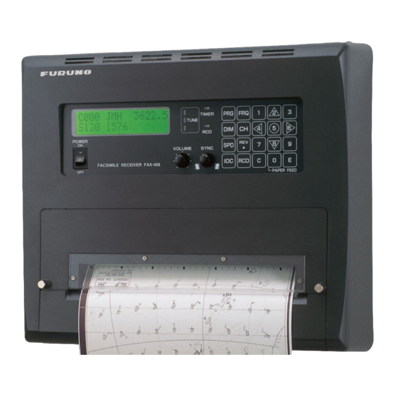
OPERATION Control Description Control panel Paper cutter POWER FACSIMILE RECEIVER FAX-408 Control, indicator POWER Turns power on and off. VOLUME Adjusts volume of Rx signal and key beep. SYNC Fine tunes the phasing signal. TIMER PRG FRQ TUNE DIM CH... - Page 12 1. OPERATION Control description (con’t from previous page) Control, indicator • Enables a setting mode (in combination with numeric key). Press the key fol- lowed by appropriate numeric key to choose setting mode. 1- Chooses internal or external receiver. 2- Sets timer reception functions. 3- Sets sleep timer.
-
Page 13: Turning The Power On/Off
Turning the Power On/Off Press the POWER key to turn the power on or off. When the power is applied, the last-used channel appears. Adjusting LCD Contrast 1. Press the PRG key. 2. Press the 7 key to show the contrast setting screen. SET CONTRAST 3. -
Page 14: Selection Of Desired Frequency, Fine Adjustment Of Frequency
1. OPERATION 1.5.2 Selection of desired frequency, fine adjustment of frequency Frequency may also be entered manually by pressing the FRQ key, and then entering frequency by using the numeric keys and the REV/ key (for entering decimal point). The available frequency range is 2000.0 - 24999.9 kHz. -
Page 15: Manual Receiving
Manual Receiving This section shows you to manually receive a facsimile broadcast. For example, you may want to receive a facsimile broadcast already in progress or receive from a facsimile station that does not use start and stop signals. 1. Press the CH key to show the channel display. C000 3622.5 S120... -
Page 16: Choosing Timer Programs For Timer Reception
1. OPERATION 3. Press the 4 key to choose STR (Store). STORE TIMER REG No. 0-F 4. Use the key to choose timer program number and press the E key. For example, choose “1” and the display then looks something like the one below. CHANNEL No. -
Page 17: Disabling Timer Operation When Awaiting Reception
1.8.3 Disabling timer operation when awaiting reception Timer programs may be deleted from the timer reception schedule as follows. 1. Press the PRG key, and the message shown below appears. TIMER RCV : OFF? PUSH E KEY 2. Press the E key. 1.8.4 Unlocking the keyboard during timer reception All keys except the PRG key are locked during recording to prevent accidental adjustment of the... -
Page 18: Processing Facsimile Images
1. OPERATION Processing Facsimile Images Speed, IOC, phasing, synchronization and image format may be adjusted during recording. 1.9.1 Speed and IOC Choose the correct speed and IOC, otherwise the image will be received as shown in the illustra- tion below. Wrong Speed or IOC and Image Wrong speed: "60"... -
Page 19: Manual Phasing
1.9.2 Manual phasing When the FAX-408 starts recording a broadcast already in progress, or noise prevents detection of the phasing signal, a dead sector (black or white stripe) may appear on the recording. This phe- nomenon is due to phase mismatching. When this occurs, adjust recording position as shown below. -
Page 20: Sleep Timer
1. OPERATION 1.10 Sleep Timer The sleep timer feature sleeps the set after reception has passed. Fax signal will not be received when the sleep timer is active. 1.10.1 Activating the sleep timer 1. Press the PRG key. 2. Press the 3 key to show the sleep mode setting mode. SLEEP MODE : OFF 1-OFF 2-ON... -
Page 21: Setting The Date And Time
1.12 Adding Facsimile Channels The FAX-408 provides a free memory for the user to store newly added channels (164 max.). The procedure below shows how to add facsimile channels, using CH711 as an example. 1. Press the PRG key followed by the 4 key. - Page 22 1. OPERATION 4. Enter call sign (3 characters), using the arrow keys, and press the E key. (Use the to choose location (with the cursor); use the enter JMH, and the display should look something like the one below. C711 JMH SET FREQUENCY 5.
-
Page 23: Isb Function
1.13 ISB Function The frequency of certain SSB multiplex broadcasts (fax and teletype) randomly shifts 1-2 kHz. To receive these broadcasts steadily, enable the ISB* function to track frequency. * ISB is a single sideband mode which is used with some SSB transmissions. Normally each side- band carries identical information, but ISB modulates two different input signals - one on the upper sideband, the other on the lower sideband. -
Page 24: Operation With An External Receiver
1. OPERATION 1.14 Operation with an External Receiver When the receive signal is particularly weak or the internal receiver is producing only blurred recordings, you may wish to receive facsimile broadcasts with an external receiver. 1.14.1 Enabling, disabling external receiver use 1. -
Page 25: Maintenance
MAINTENANCE WARNING Do not open the equipment except to replace paper. Only qualified personnel should work inside the equipment. Cleaning Dust and dirt may be removed from the main unit with a soft cloth. For stubborn dirt, water diluted mild detergent may be used. DO NOT use chemical-based cleaners to clean the cabinet or control panel, as they can remove paint and markings. - Page 26 Replacement of Recording Paper Use only the recording paper specified by FURUNO. Use of other recording paper may degrade performance, damage the thermal head and prevent detection of "paper out". When the paper is nearly out, the message PAPER OUT!! appears on the display and recording is automatically stopped.
- Page 27 1. Open the paper cutter by loosening its two screws. Detach it together with the paper compartment cover. Put the paper feed lever in the downward position. See Figure 1. 2. While pushing the paper guide (2) in the direction indicated, remove the remaining roll paper.
- Page 28 2. MAINTENANCE 4. Pull the paper feed lever upward. Draw out the paper so that it will be a little past the front of the unit. See Figure 4. 5. Attach the paper compartment cover. See Figure 6. Attach the paper cutter and tighten its two screws.
-
Page 29: Replacement Of Fuse
Replacement of Fuse A fuse at the rear of the main unit protects the equipment from overcurrent and equipment fault. If the power cannot be turned on, the fuse may have blown. WARNING Use the proper fuse. Use of a wrong fuse can result in damage to the equipment or cause fire. - Page 30 2. MAINTENANCE This page intentionally left blank.
-
Page 31: Installation
INSTALLATION Main Unit The main unit may be mounted on a tabletop or a bulkhead, using 5×25 self-tapping screws (sup- plied). When choosing a mounting location, consider the following points: • It is essential that the mounting surface is flat, otherwise blurred recordings may result, as in the example below. -
Page 32: Antenna
(For better protection against induction, use the preamp unit.) The FAX-408 can use the following antennas: • Preamp unit FAX-5 (optional supply) + 2.6 m whip antenna (optional supply) • Whip antenna (6 m, optional supply) •... -
Page 33: Whip Or Wire Antenna
5. Connect its coaxial cable directly to the antenna con- nector on the FAX-408. Note that an extension cable kit (option) is available, in lengths of 10, 20, 30, 40 and 50 m. Note 1: A wire antenna several meters in length can be connected instead of the whip antenna. -
Page 34: Wiring
3. INSTALLATION Wiring See the diagram on page S-1 for detailed wiring information. 3.3.1 Power, ground Battery Connect black wire to “-” (negative) and red wire to “+” (positive). Ground Run the ground wire (supplied) between the GND terminal at the rear of the main unit and ship’s superstructure. -
Page 35: Whip Or Wire Antenna
External receiver connection An external receiver may be used in place of the internal receiver. In this case, the receiver should have a local oscillator with very good frequency stability. Connect the external receiver to the EXT AF IN terminal at the rear of the set. This terminal operates against an input of greater than 50 mV. -
Page 36: Setting Of Sw S1 On Rcv Board (When Preamp Unit Is Used)
3. INSTALLATION 3.3.4 Setting of SW S1 on RCV board (when preamp unit is used) If the preamp unit is installed, turn on SW S1 on the RCV board in the facsimile receiver to power the preamp unit. 1. Unfasten two screws marked with arrows in the figure below to detach the paper cutter and the paper compartment cover. -
Page 37: Changing Display Language
Changing Display Language Display language is available in English, Dutch, Finnish, Norwegian, Swedish, Danish, Portu- guese, Italian, German, Spanish and French, and the default language is English. To change the display language, do the following: 1. Turn on the power while pressing and holding down the PRG key. TEST MODE (HR3) ESC POWER OFF 2. - Page 38 3. INSTALLATION This page intentionally left blank.
-
Page 39: Facsimile Station Tables
FACSIMILE STATION TABLES This section shows the location and frequency data of all the existing frequencies of facsimile transmitting stations programmed into this unit’s ROM. This data is for reference purposes. Data is subject to change without notice. Šû IM B 9âVU Area map of sxisting stations BA F... - Page 40 FACSIMILE STATION TABLES...
- Page 41 FACSIMILE STATION TABLES...
- Page 42 FACSIMILE STATION TABLES...
- Page 43 FACSIMILE STATION TABLES...
-
Page 44: Specifications
Power source ENVIRONMENTAL CONDITIONS Temperature Humidity Waterproofing (IEC60529) IPX0 Vibration FAX-408 Synthesized double superheterodyne MF/HF 2.0000 – 24.99999 MHz 2.0 kHz at -6 dB 314 channels (150 pre-set channels, 164 user channels) MF/HF 2µV at 20 dB SINAD Automatic or manual, with numeric keys... - Page 45 Output impedance Power N2.5 80 kHz – 30 MHz Wire antenna or 2.6 m whip antenna Withstand a 30 Vrms antenna input for 15 minutes 50 ohms 9 VDC, fed from facsimile receiver via coaxial cable SP - 2 FAX-408 E6262S01A...
- Page 51 H.Hayashi Jan. 27 '05...
- Page 52 T.Matsuguchi Jul.07'06...
-
Page 53: Interconnection Diagram
*3. CONNECTOR PLUG FITTED AT FACTORY. DRAWN Maki Aug. 16 '06 CHECKED TAKAHASHI.T APPROVED Hatai SCALE MASS DWG.No. REF.No. C6262-C01- B ファクシミリ受画装置 FACSIMILE RECEIVER FAX-408 アカ EXT AF クロ BLK (+) (-) IV-2sq. TITLE FAX-408 名称 ファクシミリ受画装置 相互結線図 NAME FACSIMILE RECEIVER INTERCONNECTION DIAGRAM 選択...
Need help?
Do you have a question about the FAX-408 and is the answer not in the manual?
Questions and answers