Table of Contents
Advertisement
Quick Links
Trademarks
®
®
Autel
, MaxiSys
trademarks of Autel Intelligent Technology Corp., Ltd., registered in China, the United
States and other countries. All other marks are trademarks or registered trademarks of
their respective holders.
Copyright Information
No part of this manual may be reproduced, stored in a retrieval system or transmitted,
in any form or by any means, electronic, mechanical, photocopying, recording, or
otherwise without the prior written permission of Autel.
Disclaimer of Warranties and Limitation of Liabilities
All information, specifications and illustrations in this manual are based on the latest
information available at the time of printing.
Autel reserves the right to make changes at any time without notice. While information
of this manual has been carefully checked for accuracy, no guarantee is given for the
completeness and correctness of the contents, including but not limited to the product
specifications, functions, and illustrations.
Autel will not be liable for any direct, special, incidental, indirect damages or any
economic consequential damages (including the loss of profits).
IMPORTANT
Before operating or maintaining this unit, please read this manual carefully, paying extra
attention to the safety warnings and precautions.
For Services and Support
pro.autel.com
www.autel.com
1-855-288-3587/1-855-AUTELUS (North America)
0086-755-86147779 (China)
support@autel.com
For technical assistance in all other markets, please contact your local selling agent.
®
, MaxiDAS
, MaxiScan
®
®
, MaxiCheck
, and MaxiRecorder
i
®
are
Advertisement
Table of Contents

Related Manuals for Autel MaxiBAS BT609


Summary of Contents for Autel MaxiBAS BT609
- Page 1 All information, specifications and illustrations in this manual are based on the latest information available at the time of printing. Autel reserves the right to make changes at any time without notice. While information of this manual has been carefully checked for accuracy, no guarantee is given for the completeness and correctness of the contents, including but not limited to the product specifications, functions, and illustrations.
- Page 2 Safety Instructions The safety messages herein cover situations Autel is aware of. Autel cannot know, evaluate or advise you as to all of the possible hazards. You must be certain that any...
- Page 3 DANGER When an engine is operating, keep the service area WELL VENTILATED or attach a building exhaust removal system to the engine exhaust system. Engines produce carbon monoxide, an odorless, poisonous gas that causes slower reaction time and can lead to serious personal injury or loss of life.
-
Page 4: Table Of Contents
CONTENTS SAFETY INFORMATION ....................ii SAFETY MESSAGES ....................ii SAFETY INSTRUCTIONS ..................... ii ........................1 ONVENTIONS 2.1 M BAS BT609 T ................... 4 ESTER 2.1.1 Function Description ..................4 2.1.2 Power Sources....................5 2.1.3 Technical Specifications ................6 2.2 M BAS B200 S .................. - Page 5 4.4 G ..................... 25 ENERATOR 5.1 T ..................... 27 ROCEDURE 5.2 T ......................28 ESULTS 7.1 A ) ..........31 EGISTRATION AFTER BATTERY REPLACEMENT 7.2 BMS R ......................32 ESET 7.3 E ..................32 LECTRIC PPLIANCE ESET 7.4 S ....................33 PECIAL UNCTION 7.5 B...
-
Page 6: Safety Information
9.9 L ........................ 53 9.10 A ......................59 CTIVE 9.11 G OBDII O .................. 60 ENERIC PERATIONS 9.11.1 General Procedure ..................60 9.11.2 Function Descriptions ................61 9.12 D ....................64 IAGNOSTIC EPORT 9.13 E ....................65 IAGNOSTICS 10.1 O .................... - Page 7 14.1 U ........................88 14.2 L ......................89 ANGUAGE 14.3 P ....................89 RINTING ETTINGS 14.3.1 Printing Operations ................... 89 14.4 N ..................... 90 OTIFICATION ENTER 14.5 A ......................90 PDATE 14.6 V ......................90 EHICLE 14.7 B ......................91 ATTERY 14.8 S ....................
- Page 8 20.4.1 Technical Support ................... 108 20.4.2 Repair Service ..................109 viii...
-
Page 9: Conventions
Using This Manual This manual contains device usage instructions for the Autel MaxiBAS BT609 Battery Tester. Some illustrations shown in this manual may contain modules and optional equipment that are not included in your system. Contact your sales representative for availability of other modules and optional tools or accessories. - Page 10 Hyperlink Hyperlinks, or links, that take you to other related articles, procedures, and illustrations are available in electronic documents. Blue italic text indicates a selectable hyperlink and blue underlined text indicates a website link or an email address link. Illustrations Illustrations used in this manual are samples, the actual testing screen may vary for each vehicle being tested.
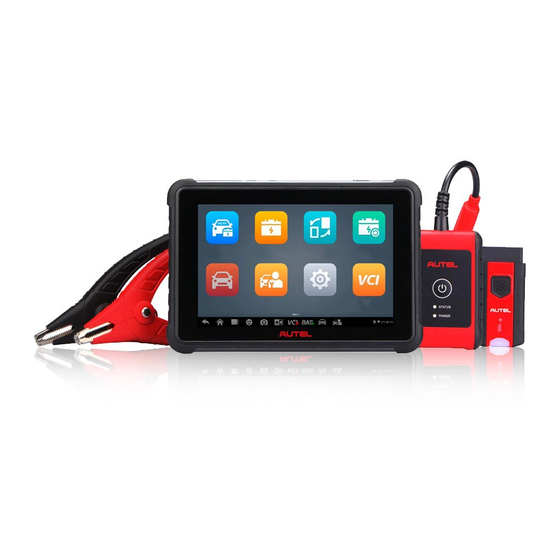
- Page 11 General Introduction The MaxiBAS BT609 wireless battery and diagnostics system uses the adaptive conductance technology to more accurately determine the health of battery than traditional battery testers. The BT609 can quickly display both voltage and health status of the existing battery, register a new battery, and perform advanced battery and electrical diagnostics.
-
Page 12: Maxibas Bt609 Tester
MaxiBAS BT609 Tester 2.1.1 Function Description Figure 2-1 MaxiBAS BT609 Front/Back/Side View 7.0-inch Touchscreen Built-in Microphone Power LED Ambient Light Sensor... -
Page 13: Power Sources
Speaker Camera Camera Flash Type-C USB OTG Port Type-C USB Host Port 10. Micro SD Card Slot 11. Lock/Power Button Table 2-1 Power LED Description Color Description Lights solid green when the battery is fully charged. Green Flashes green while charging, and the tablet will Power automatically powers on. -
Page 14: Technical Specifications
2.1.3 Technical Specifications Item Description Operating System Android 9.0 Screen Display 7'' LCD touchscreen with 1280 x 800 pixel resolution Storage 64 GB Wi-Fi (802.11 a/b/g/n/ac) Connectivity USB 2.0, Type C (1 USB OTG + 1 USB Host) ... -
Page 15: Maxibas B200 Series Tester
2.2 MaxiBAS B200 Series Tester 2.2.1 Function Description Figure 2-2 MaxiBAS B200 View Power Button Status LED Power LED USB Port Multimeter Cable Port Battery Clamp Cable Table 2-2 LED Description Color Description Flashing Green The tester is communicating via USB cable. Status Flashing Blue The tester is communicating via Bluetooth. -
Page 16: Power Sources
2.2.2 Power Sources The B200 tester can receive power from the following sources: Internal Battery Pack AC/DC Power Supply Internal Battery Pack The B200 can be powered with the internal rechargeable battery. AC/DC Power Supply — Using Power Adapter The tester can be powered from an electrical outlet using the AC/DC power adapter. -
Page 17: Maxivci V200 - Vehicle Communication Interface (Vci)
2.3 MaxiVCI V200 — Vehicle Communication Interface (VCI) 2.3.1 Function Description Figure 2-3 MaxiVCI V200 View Flashlight Power Button Power LED Vehicle/Connection LED Vehicle Data Connector (16-pin) USB Port Table 2-3 VCI LED Description Color Description Yellow VCI is powered on and performing self-check. Power LED VCI is ready for use. -
Page 18: Power Sources
2.3.2 Power Sources The VCI device can receive power from following sources: Vehicle Power AC/DC Power Supply Vehicle Power The VCI device operates on 12/24 Volt vehicle power, which is powered by the vehicle data connection port. The device powers on whenever it is connected to an OBDII/EOBD- compliant Data Link Connector (DLC). -
Page 19: Other Accessories
2.4 Other Accessories Battery Side Post Terminal Type S (2 pcs) Connects the battery posts and the clamps. Battery Side Post Terminal Type T (2 pcs) Connects the battery posts and the clamps. Power Adapter Together with the USB cable, connects the unit to an external DC power port for power supply. -
Page 20: Power Up
Getting Started Ensure the unit is sufficiently charged. 3.1 Power Up Press and hold the Lock/Power button to power up the BT609. The system will boot up and display the Job Menu. Figure 3-1 Sample BT609 Job Menu Application Buttons Page Indicator and Navigation Buttons Status Icons NOTE... -
Page 21: Application Buttons
Accesses the VCI Manager, BAS Manager, System Settings Settings Menu, and more. Settings on page 88. Accesses VCI connection menu. VCI Manager VCI Manager on page 92. Synchronizes Autel's online service database with Support the diagnostic tablet. Support on page 96. -
Page 22: Page Indicator And Navigation Buttons
Button Name Description Remotely controls the device from any computer or even from another mobile device. Transfers files Remote Desktop from the device to a computer, or vice versa. Remote Desktop on page 101. Provides associated website bookmarks to allow quick access to product update, service, support, Quick Link and other information. -
Page 23: System Status Icons
Icon Name Description Opens the VCI Manager application. A green icon at the bottom-right corner indicates the VCI device is VCI Connection connected via Bluetooth, while a red “x” icon will display if connection fails. Opens the VCI Manager application. A green icon at the bottom-right corner indicates the B200 tester is BAS Connection connected via Bluetooth, while a red “x”... -
Page 24: Power Off
3.2 Power Off All vehicle communications should be terminated before shutting down the tablet. A warning message displays if a shutdown is attempted while the tablet is communicating with the vehicle. Forcing a shutdown while the tablet is communicating with the vehicle may lead to ECU problems on some vehicles. -
Page 25: Establish Vehicle Communication
3.4 Establish Vehicle Communication The Diagnostics operations require pairing the MaxiBAS BT609 tablet with the vehicle through the VCI device (V200) via Bluetooth. To establish proper vehicle communication to the tablet, perform the following steps: Connect the VCI device to the vehicle’s DLC for both communication and power source. - Page 26 NOTE If no VCI device is found, this may indicate that the signal strength is too weak to be detected. Reposition the VCI device and remove all possible objects that may cause signal interference. The device name will display as “Maxi” suffixed with a serial number. Check the serial number on your VCI label and select the desired device for pairing.
- Page 27 In-vehicle Test The In-vehicle Test is used for testing batteries that are installed in a vehicle. An in-vehicle test covers battery, starter, and generator tests. These tests help determine the health status of the battery, starter, and generator. IMPORTANT The Disclaimer page will appear when accessing any function on the Home screen for the first time.
-
Page 28: Start The Test
Name Button Description Scan Tap to scan license plate. License Scan VIN Tap to scan Vehicle Identification Number (VIN). Battery Tap to check the battery location diagram. Location Next Tap to proceed. Home Returns to the MaxiBAS Job Menu. Back Returns to the previous screen. - Page 29 Confirm Vehicle Information Figure 4-2 Sample Vehicle Information Screen NOTE The Scan License feature is supported in limited countries and regions. Manually enter the license number if it is not available. The vehicle information will be automatically identified when vehicle communication is established.
-
Page 30: Battery Test
NOTE If the Visual inspection is not enabled in Settings, the user will be directed to the “Battery Test” main screen after completing the vehicle information. Figure 4-3 Sample Visual Inspection Screen 1 4.2 Battery Test Follow the on-screen instructions, check the boxes once listed tasks are completed, and tap Start Testing. - Page 31 Wait until the test is completed. The test results will be displayed on the tablet. Figure 4-5 Sample Battery Test Result Screen Process Buttons Test Report Function Buttons Process Buttons Tap any of the process buttons to advance to the corresponding test — battery test, starter test or generator test.
-
Page 32: Starter Test
Name Description Tap to view the test data and results in report form. Tap Print on the bottom Report of the screen to print the test report. Tap Email to send the test report to an email address. Tap to continue to replace the battery. Replace Battery Battery Replace... -
Page 33: Generator Test
4.4 Generator Test Follow the on-screen instructions to complete the test. The test results will be displayed as follows: Figure 4-7 Sample Generator Test Result Screen Table 4-4 Generator Test Results Result Description Charging Normal The generator is good. The belt linking the starter and the generator is loose. - Page 34 Connecting Current Clamp Before connecting the current clamp, ensure the multimeter (DM100) is properly connected to the B200 series tester. (See section 11.2 for multimeter connection instructions.) Plug the red output cable into the red input of the multimeter and the black output cable into the black input.
-
Page 35: Test Procedure
Out-Vehicle Test Out-vehicle Test is used to test the condition of batteries that are not connected to a vehicle. This function aims to check the health status of the battery only. The compatible battery types and standards are as follows: Types: FLOODED, AGM, AGM SPIRAL, EFB, and GEL Standards: CCA, SAE, CA, EN, EN2, IEC, DIN, JIS, MCA, BCI, and GB 5.1 Test Procedure... -
Page 36: Test Results
Figure 5-2 Sample Out-vehicle Test Results Screen 5.2 Test Results Icons are color-coded to indicate status. Result Description Good Battery Battery meets required standards. Battery is good, but low on charge. Fully charge the Good & Recharge battery. Check for causes of low charge. Battery requires charge to determine its condition. - Page 37 Battery Replace The Battery Replace function guides you through replacing the battery step by step. The battery replacement process includes battery type selection, preparation for battery replacement, replacing the battery, new battery selection, new battery test, and battery registration. To replace the battery: Tap Help at the bottom of each screen to read all the help information carefully before operation, then follow the on-screen instructions to complete the battery...
- Page 38 Figure 6-2 Sample New Battery Test Results Screen When the new battery test is completed, tap Register to automatically proceed with the Auto Registration in the Battery Reset chapter.
-
Page 39: Auto Registration (After Battery Replacement)
Battery Reset The Battery Reset allows users to access the following functions: Auto registration (after battery replacement), BMS reset, Electric appliance reset, Special function and Battery usage history. This interface differs depending on the specific vehicle. Figure 7-1 Sample Battery Reset Main Menu Screen 7.1 Auto Registration (after battery replacement) The Auto registration is often used after the successful installation of a new battery. -
Page 40: Bms Reset
7.2 BMS Reset The BMS reset feature enables you to register a new battery after a battery replacement. The BMS Reset function varies by vehicle make. Please follow the on-screen instructions to perform the desired functions. Figure 7-2 Sample BMS Reset Screen 7.3 Electric Appliance Reset When the vehicle power is interrupted in order to replace the battery, and a memory saver has not been used, position settings on some vehicle components will be lost. -
Page 41: Special Function
7.4 Special Function The special function varies by vehicle make. Functions other than Battery Reset are categorized as special functions. Please follow the on-screen instructions to perform the desired functions. Figure 7-4 Sample Special Function Screen (BMW vehicles) 7.5 Battery Usage History The Battery Usage History function will display different tests for different vehicles. - Page 42 Top Toolbar Buttons Main Section Left column — displays the test menu, from which the user can choose the desired test or other content, such as suggestions for the vehicle battery. Right column — displays test results, which can be shown in a bar graph, text, or line chart.
-
Page 43: Lithium-Ion Battery Test
Lithium The Lithium function provides access to various functions related to the Lithium-ion battery, including Lithium-ion battery test, ECU information check, special function, electric appliance reset, and BMS reset. The functions of electric appliance reset and BMS reset are similar to those of the BMS Reset function in Chapter 7. -
Page 44: Visual Inspection
8.1.1 Visual Inspection After entering the battery test, first check the battery for any damage. If any problem depicted on the screen is observed on the battery, swipe the toggle(s) to the right. Tap Next to continue. Figure 8-2 Sample Visual Inspection Screen 8.1.2 Trouble Codes This function retrieves and displays the DTCs from the vehicle’s control system. -
Page 45: Live Data
Figure 8-3 Sample Trouble Codes Screen Upper Toolbar Main Section Indicates the code name and the status. A description of the code. Function Buttons 8.1.3 Live Data The Live data function will display the data list for the selected module. The parameters will display in the order that they are transmitted by the ECU, and the screen varies depending on the vehicle make. - Page 46 Upper Toolbar Main Section Right column — displays the parameter names. Left column — displays the values of the parameters. When a value exceeds the set limits, it will display red. Function Button Display Mode There are four types of display modes available for data viewing, which allow you to view various types of parameters in the most suitable way.
-
Page 47: Ecu Information
8.2 ECU Information This function retrieves and displays the specific information for the tested control unit, including production type and serial number. Figure 8-6 Sample ECU Information Screen 8.3 Special Function The special function in this section specifically tests the vehicles installed with lithium batteries, different from that of the BMS Reset chapter. -
Page 48: Getting Started
Diagnostics NOTE Prior to the use of the Diagnostics function, ensure the VCI (V200) is properly connected to and is communicating with the tablet. The Diagnostics application can access the electronic control module of multiple vehicle control systems, including but not limited to the engine, transmission, antilock brake system (ABS), and airbag system (SRS). - Page 49 Top Toolbar Buttons The operations of the toolbar buttons at the top of the screen are listed and described in the table below: Table 9-1 Top Toolbar Buttons Name Button Description Home Returns to the MaxiBAS Job Menu. Tap to open a drop-down list: tap Auto detect for auto VIN detection;...
-
Page 50: Vehicle Identification
9.2 Vehicle Identification The MaxiBAS diagnostics system supports five methods of Vehicle Identification. Auto VIN Scan Manual Input Scan VIN/License Manual Vehicle Selection OBDII Direct Entry 9.2.1 Auto VIN Scan The MaxiBAS diagnostics system features the latest VIN-based Auto VIN Scan function to identify vehicles with just one tap, enabling you to quickly identify the exact vehicle and scan its available systems for fault codes. -
Page 51: Manual Input
Figure 9-3 Sample Vehicle Selection Screen 9.2.2 Manual Input For vehicles that do not support the Auto VIN Scan function, the MaxiBAS diagnostics system allows you to enter the vehicle VIN or license number manually, or simply take a photo of the VIN sticker for quick vehicle identification. ... -
Page 52: Scan Vin
Figure 9-4 Sample Enter VIN Screen 9.2.3 Scan VIN Tap Scan VIN in the drop-down list (see Figure 9-2), and the camera will open. On the right side of the screen, from top to bottom, three options are available: Scan Bar Code, Scan VIN, and Scan License. -
Page 53: Alternative Vehicle Identification
Step-by-step Vehicle Selection This mode of vehicle selection is menu driven. Tap the Manufacturer icon on the Vehicle Menu screen and the Select diagnostic type screen displays. Tap Manual Selection. Select the vehicle information (e.g., brand, model, capacity, engine type, and model year). Each selection advances you to the next screen. -
Page 54: Auto Scan
Figure 9-6 Sample Diagnostics Menu Screen 9.4 Auto Scan The Auto Scan function performs a comprehensive scan on all the systems in the vehicle ECU to locate faults and retrieve DTCs. To perform an Auto Scan: 1. Tap the Diagnostics button on the MaxiBAS Job Menu. Choose the corresponding vehicle information and enter the vehicle diagnostics page. - Page 55 Use this function when encountering an error while testing or diagnosing a vehicle. This function will record communication data and ECU information from the test vehicle and send it to Autel technical Data Logging staff to review and provide a solution.
- Page 56 To print the Diagnostics data: Tap the Diagnostics button on the Job Menu. The Print button on the diagnostics toolbar is available throughout the Diagnostics operations. Tap Print and a drop-down menu will display. Print This Page — prints a copy of the current screen only. Print All Data —...
-
Page 57: Control Unit
Pass | No Fault: Indicates the system was scanned and no faults were detected. Not Scanned: Indicates the system has not been scanned. No Response: Indicates the system has not received a response. Column 4 — to perform further diagnosis or testing on a specific system item, tap the arrow button to the right of that item. -
Page 58: Screen Messages
ECU information — displays detailed ECU information. Read codes — displays detailed DTC information retrieved from the vehicle control module. Erase codes — erases DTC records and other data from the vehicle's ECU. Live data — retrieves and displays live data and parameters from the vehicle's ECU. ... -
Page 59: Read Codes
Figure 9-9 Sample ECU Information Screen Diagnostics Toolbar (see Table 9-2 Diagnostics Toolbar Buttons) Status Information Bar Main Section — the left column displays the item names, while the right column displays the specifications or descriptions. Function Buttons — in this example, only an ESC button is available. Tap it to exit after viewing. -
Page 60: Erase Codes
Diagnostics Toolbar (see Table 9-2 Diagnostics Toolbar Buttons) Status Information Bar Main Section Column 1 — displays retrieved codes from the vehicle. Column 2 — indicates the status of the retrieved codes. Column 3 — provides detailed descriptions for retrieved codes. ... -
Page 61: Live Data
9.9 Live Data When this function is selected, the screen will display the data list for the selected module. The parameters will display in the order that they are transmitted by the ECU, so expect variation among vehicles. Gesture scrolling allows you to quickly move through the data list. Drag your finger up or down on the screen to reposition the parameters being displayed if the data occupies more than one screen. - Page 62 Function Buttons The operations of all available function buttons on the Live Data screen are described below: Cancel All — tap this button to cancel all selected parameters. Up to 50 parameters can be selected at one time. Show Selected/Show All — tap this button to switch between the two options. One displays the selected parameters, the other displays all available items.
- Page 63 Freeze — displays a still capture of retrieved data. Resume — tap to exit the freeze data mode and return to live data display. Previous Frame — moves to the previous frame of frozen data. Play/Pause — tap to play/pause the frozen data. ...
- Page 64 Figure 9-12 Sample Display Mode Screen Each parameter item displays its selected mode independently. Analog Gauge Mode — displays the parameters in gauge charts. Text Mode — the default mode that displays the parameters as a text list. NOTE Status parameters, such as a switch reading like ON, OFF, TRUE, and FALSE, can only be displayed in Text Mode.
- Page 65 Figure 9-13 Sample Waveform Graph Mode Screen Settings Button (SetY) — sets the minimum and maximum values of the Y axis. Scale Button — changes the scale values. There are two scale buttons displaying above the waveform graph to the right side, which can be used to change the scale values of the X axis and Y axis of the graph.
- Page 66 The parameter is selected automatically in the left column. Select a color from the second column. Select a line thickness from the right column. Tap Done to save the settings and exit, or tap Cancel to exit without saving. NOTE In full screen mode, you can edit the waveform color and line thickness by tapping the Edit Button on the top-right corner of the screen.
-
Page 67: Active Test
To set a trigger: Tap the drop-down button on the right side of a parameter to open a submenu. Tap the Trigger button on the right side of the submenu to open the Trigger Settings window. Tap the MIN button on the right side, and enter the required minimum value. Tap the MAX button on the right side, and enter the required maximum value. -
Page 68: Generic Obdii Operations
Figure 9-15 Sample Active Test Screen The function buttons on the lower-right corner of the Active Test screen manipulate the test signals. Operational instructions are displayed in the main section of the test screen. Follow the on-screen instructions and make appropriate selections to complete the tests. Tap the ESC button to exit the test when finished. -
Page 69: Function Descriptions
Protocol — select to open a submenu of available protocols. A communications protocol is a standardized way of data communication between an ECM and a diagnostic tool. Global OBD may use several different communications protocols. Select a specific protocol if the Protocol option is selected. Wait for the OBDII Diagnostics Menu to appear. - Page 70 Figure 9-17 Sample DTC & FFD Screen Current Codes Current codes are emission-related DTCs from the ECU of the vehicle. OBDII/EOBD codes are prioritized according to their emissions severity, with higher-priority codes overwriting lower-priority ones. The priority of the code determines the illumination of the Malfunction Indicator Light (MIL) and the codes erase procedure.
- Page 71 Erase Codes This option is used to clear all emission-related diagnostic data including DTCs, freeze frame data and specific manufacturer-enhanced data from the vehicle ECU. This option resets the I/M Readiness Monitor Status for all vehicle monitors to Not Ready or Not Complete status.
-
Page 72: Diagnostic Report
Vehicle Information This function enables the display of the vehicle identification number (VIN), calibration identification number, Calibration Verification Number (CVN), and other vehicle information. Vehicle Status This function checks the current condition of the vehicle, such as the communications protocols of OBDII modules, quantity of fault codes, and the status of the Malfunction Indicator Light (MIL). -
Page 73: Exit Diagnostics
Tap the button on the Diagnostics Toolbar, and select Save all data to save a PDF document or select Save this page to save the screenshot of the current page. Figure 9-19 Sample Auto Scan Screen Via the buttons on the navigation bar: The diagnostic report can also be viewed from the Read Codes and Live Data screens. - Page 74 To exit the Diagnostics application: On an active diagnostic screen, tap the Back or ESC button to exit a diagnostic session; Tap the Vehicle Swap button on the diagnostics toolbar to return to the Vehicle Menu screen. On the Vehicle Menu screen, tap the Home button on the top toolbar, or tap the Back button on the navigation bar at the bottom of the screen.
-
Page 75: Oil Reset Service
Service The Service section is specially designed to provide quick access to the vehicle systems for various scheduled service and maintenance tasks. The typical service operation screen is a series of menu-driven commands. Follow the on-screen instructions to select appropriate options, enter values or data, and perform necessary actions. -
Page 76: Electric Parking Brake (Epb) Service
Ensure that the EPB control system is reactivated after the maintenance work has been completed. NOTE Autel accepts no responsibility for any accident or injury arising from the maintenance of the EPB system. 10.3 Tire Pressure Monitoring System (TPMS) Service This function allows you to quickly look up the tire sensor IDs from the vehicle's ECU and to perform TPMS replacement and reset procedures after tire sensors are replaced. -
Page 77: Diesel Particle Filter (Dpf) Service
NOTE This function is not supported by all vehicles. The sub functions and actual test screens of the BMS may vary by vehicle. Please follow the on-screen instructions to make correct selection. The vehicle may use either a sealed lead-acid battery or an Absorbed Glass Mat (AGM) battery. -
Page 78: Immobilizer (Immo) Service
NOTE The DPF will not regenerate when the engine management light is on or when there is a faulty EGR valve. The ECU must be re-adapted when replacing the DPF and when topping up the fuel additive Eolys. If the vehicle needs to be driven in order to perform a DPF service, a second person is required for the function: One person should drive the vehicle while the other person observes the screen on the tool. - Page 79 Accident repairs where damage to the SAS, SAS assembly, or any part of the steering system may have occurred NOTE Autel accepts no responsibility for any accident or injury arising from servicing the SAS system. When interpreting DTCs retrieved from the vehicle, always follow the manufacturer's recommendation for repair.
-
Page 80: Safety Information
Multimeter The multimeter (sold separately) is a multi-function, multi-range measuring instrument. Connect the multimeter to the B200 device and access its applications directly from the BT609 Home screen to perform leakage detection, relative compression test, and basic functions, including AC/DC voltage, AC/DC current, resistance measurements, diode, and connectivity tests. -
Page 81: Connecting The Multimeter
Use the test leads or probes supplied with the product, or compatible terminals. Inspect the test leads or probes for damage before use. When using probes, keep fingers behind the finger guards on the probes. Use the supplied replacement fuses or specified replacement parts. Always consider electrical and electronic equipment to be energized (live). - Page 82 Connect the red alligator clip/red probe to the other end of the red test lead, and the black alligator clip/black probe to the black test lead. Power on the BT609 and tap the Multimeter button to enter the application. ...
-
Page 83: Leakage Detection
11.3 Leakage Detection Before opening the Multimeter application, ensure the multimeter device (DM100, Digital Multimeter 100) is connected to the tester via the multimeter cable. The device will beep when entering the application after properly connected with the tester. Some current will flow through the protective ground conductor to ground in an electrical installation. -
Page 84: Relative Compression Test
Figure 11-3 Sample Leakage Detection (Multimeter Model) Screen IMPORTANT Before performing leakage detection, ensure that the battery voltage is above 12.6 V; otherwise, the engine should be turned on to charge the battery. The test result may be compromised if the battery voltage is below 12.6 V. 11.4 Relative Compression Test The Relative compression test is helpful to diagnose misfires due to a compression issue. -
Page 85: Basic Function
11.5 Basic Function Basic functions give the user access to tests that cover AC/DC voltage, AC/DC current, resistance measurements, diodes, and connectivity. Figure 11-5 Sample Multimeter Screen 11.5.1 Screen Layout and Operation Upper Toolbar Buttons and Multimeter Icon Digital Display Main Section Measurement Type Selection and Reset Button Buttons and Multimeter Icon... - Page 86 This section displays the digital measurement results. Main Section The Main Section features a coordinate grid with the X-axis representing the time duration and the Y-axis representing the amplitude level. Measurement Type Selection This multimeter can be used to measure AC voltage, DC voltage, resistance, AC electricity, DC electricity, diodes, and connectivity.
- Page 87 Data Manager The Data Manager allows you to store, print, and review saved files, manage workshop information, customer information records, and store test vehicle history records. Selecting the Data Manager opens the file system menu. There are eight functions available. Figure 12-1 Sample Data Manager Main Screen The table below briefly describes the function buttons in the Data Manager.
-
Page 88: Vehicle History
Name Button Description Uninstall Apps Tap to uninstall applications. Tap to review communications data and ECU information for the test vehicle. The saved data can Data Logging be sent to the technical center via the Internet for review and for possible resolution. 12.1 Vehicle History This function stores vehicle test records, including vehicle information and the retrieved DTCs from previous diagnostic sessions. -
Page 89: Historical Test Records
Select a vehicle thumbnail and choose a record. A Test History record sheet will display. Review the recorded information for the test vehicle, and tap the Diagnostics button on the upper-right corner to continue diagnostics. NOTE The BT609 tablet must establish a connection to the VCI device to restart test sessions on previously tested vehicles. -
Page 90: Workshop Information
12.2 Workshop Information The Workshop Information form allows you to enter, edit, and save detailed workshop profile information, such as shop name, business address, phone number, and other remarks, which, when printing vehicle diagnostic reports and other associated test files, will display as the header of the printed documents. -
Page 91: Image
To edit a customer account: Tap Data Manager on the MaxiBAS Job Menu. Select Customer. Select a customer account by tapping the corresponding name card. A Customer Information record will display. Tap Edit on the top toolbar to edit the record. Tap on the enter field to edit the information, and enter updated information. -
Page 92: Pdf Files
Table 12–2 Toolbar Buttons in Image Database Name Button Description Back Tap to return to the previous screen. Enter Search Enter the search page. Display the editing toolbar to select, delete, print, or Enter Edit email images. Cancel Close the editing toolbar or cancel file search. Quickly searches for an image by entering the time Search of the screenshot. -
Page 93: Review Data
12.6 Review Data The Review Data section allows you to play back recorded data frames from live data. On the Review Data main screen, select a record to play back. Figure 12-6 Sample Review Data Screen Main Section — displays the recorded data frames. Navigation Toolbar —... - Page 94 Update The internal programming of the MaxiBAS Diagnostics System, known as the firmware, can be updated through the Update application. Firmware updates enhance the performance of the MaxiBAS applications, typically by adding new tests, expanded vehicle coverage or enhanced applications. The device automatically searches for available updates for all of the MaxiBAS components when it is connected to the Internet.
- Page 95 Main Section Left Column — displays vehicle logos and software update version information. Middle Column — displays a brief introduction about the new changes to the firmware operation or capabilities. Tap the button to view more details, and tap the dim area outside the information box to close the window.
-
Page 96: Unit
Settings Access the Settings menu to adjust default settings and view information about the MaxiBAS diagnostic system. The following options are available in the MaxiBAS settings menu: Unit Language Printing settings Notification center Auto update Vehicle list ... -
Page 97: Language
To install the MaxiSys Printer driver: 1. Download the Maxi PC Suite from www.autel.com > Support > Downloads > Autel Update Tools, and install to your computer. 2. Double-click on the Setup.exe. 3. Select an installation language to launch the installation wizard. -
Page 98: Notification Center
4. Tap the Print button on the toolbar of the tablet. A test document will be sent to the computer. If the Auto Print option in the MaxiSys Printer is selected, the MaxiSys printer will automatically print the received document. ... -
Page 99: Battery Test
Tap the Home button in the top-left corner to return to the MaxiBAS Job Menu, or select another settings option for further system setup. 14.7 Battery Test This option allows you to enable the following functions: Current clamp This toggle must be turned ON before connecting the current clamp to measure the current. - Page 100 VCI Manager The VCI Manager is an application for connecting the MaxiBAS tablet with a VCI device and checking the communication status. The MaxiBAS diagnostics system supports battery diagnostics with the B200 series tester. Figure 15-1 Sample VCI Manager Screen Connection Mode —...
-
Page 101: Vci Bt Pairing
15.1 VCI BT Pairing Bluetooth Paring provides a simple wireless connection. The VCI device needs to be either connected to a vehicle or to an available power source, so that it is powered up during the synchronization procedure. Make sure the tablet is fully charged or connected to a power supply. -
Page 102: Vci Update
bottom of the screen will display a green BT mark, indicating the tablet is connected to the VCI device. Figure 15-2 Sample BAS BT Pairing Screen 15.3 VCI Update The Update module provides the latest update for the VCI device. Before upgrading the VCI firmware, please ensure your network connection is stable. -
Page 103: Bas Update
To update the VCI device software: Power on the tablet. Connect the VCI device to the tablet via Bluetooth or USB cable. Tap the VCI Manager on the MaxiBAS Job Menu of the tablet. Select VCI Update from the connection mode list. The current version and the latest version of the software will be displayed. -
Page 104: Product Registration
Visit the website: https://pro.autel.com/. If you already have an Autel account, sign in with your account ID and password. If you are a new member to Autel, click on the Create Autel ID button on the left pane to create an Autel account. -
Page 105: Support Screen Layout
16.3.1 Personal Info The User Info and Device Info are both included under the Personal Info section. User Info — displays detailed information of your registered online Autel account, such as your Autel ID, Name, Address and other contact information. ... -
Page 106: Service Info
The Service Info section displays a detailed record list of the device's service history information. Each time the device is sent back to Autel for repair, the device's serial number and the detailed repair information, such as the fault type, changed components, or system reinstallation will be recorded and updated to the associated online product account that will be synchronized to the Service Info section. -
Page 107: Data Logging
Select the required processing time on the last section according to the urgency of the case. Tap Submit to send the completed form to Autel's online service center. The submitted complaints will be carefully read and handled by the service personnel. -
Page 108: Training
16.6 Training The Training section provides quick links to Autel's online video library. Select a video channel by language to see all available Autel online tutorial videos on topics such as product usage techniques and vehicle diagnostics practices. 16.7 FAQ... - Page 109 The Remote Desktop application launches the TeamViewer Quick Support program, which is a simple, fast, and secure remote-control interface. You can use the application to receive remote support from Autel's support center, colleagues or friends by allowing them to control your MaxiBAS tester on their PC via the TeamViewer software.
- Page 110 Provide your ID to the partner and have them to send you a remote control request. A prompt will appear asking you to allow remote control on your device. Tap Allow to accept or Deny to reject the request. Refer to the associated TeamViewer documents for additional information.
- Page 111 Quick Link The Quick Link application provides you with convenient access to Autel's official website and many other well-known sites in the automotive service industry to provide technical help, knowledge bases, forums, training and expert consultations. Figure 18-1 Sample Quick Link Screen To open a quick link: ...
- Page 112 MaxiViewer The MaxiViewer allows you to search the functions supported by our tools and the version information. There are two ways of searching, either by the tool and the vehicle or by functions. To search by the vehicle: Tap the MaxiViewer application on the MaxiBAS Job Menu. The MaxiViewer application screen will display.
- Page 113 NOTE Partial search is supported: type in any part of the function-related keywords to find all available information.
-
Page 114: Maintenance Instructions
Maintenance and Service To ensure that the tablet, the battery tester, and the combined VCI unit perform at their optimum level, we advise that the product maintenance instructions covered in this section are read and followed. 20.1 Maintenance Instructions The following shows how to maintain your devices, together with precautions to take. Use a soft cloth and alcohol or a mild window cleaner to clean the touch screen of the ... -
Page 115: About Battery Usage
Your device may have not been connected to the charger properly. Check the connector. NOTE If the problems persist, please contact the Autel technical support personnel or your local distributor. 20.3 About Battery Usage Your tester is powered by a built-in Lithium-ion Polymer battery. This means that, unlike other forms of battery technology, you can recharge your battery while some charge remains without reducing your tester’s autonomy due to the “battery memory effect”... -
Page 116: Service Procedures
20.4.1 Technical Support If you have any question or problem on the operation of the product, please contact us. AUTEL NORTH AMERICA Phone: 1-855-AUTEL-US (288-3587) (855-288-3587) Monday-Friday 9am-6pm Website: www.autel.com Email: ussupport@autel.com ... - Page 117 For technical assistance in other markets, please contact your local distributor. 20.4.2 Repair Service If it becomes necessary to return your device for repair, please download the repair service form from www.autel.com, and fill in the form. The following information must be included: Contact name ...
- Page 118 Compliance Information FCC Compliance FCC ID: WQ8MAXIBASBT609 This device complies with part 15 of the FCC Rules and Industry Canada’s license-exempt RSSs. Operation is subject to the following two conditions: This device may not cause harmful interference, and This device must accept any interference received, including interference that may cause undesired operation.
- Page 119 The exposure standard for wireless devices employs a unit of measurement known as the Specific Absorption Rate, or SAR. The SAR limit set by the FCC is 1.6 W/Kg. Tests for SAR are conducted using standard operating positions accepted by the FCC with the device transmitting at its highest certified power level in all tested frequency bands.
- Page 120 Warranty Limited One Year Warranty Autel Intelligent Technology Corp., Ltd. (the Company) warrants to the original retail purchaser of this MaxiBAS tablet that should this product or any part thereof during normal usage and under normal conditions be proven defective in material or workmanship and results in product failure within 1 year period from the date of purchase, such defect(s) will be repaired, or replaced (with new or rebuilt parts) with Proof of Purchase, at the Company’s...
Need help?
Do you have a question about the MaxiBAS BT609 and is the answer not in the manual?
Questions and answers