Table of Contents
Advertisement
Quick Links
Trademarks
®
®
Autel
, MaxiSys
trademarks of Autel Intelligent Technology Corp., Ltd., registered in China, the United
States and other countries. All other marks are trademarks or registered trademarks of
their respective holders.
Copyright Information
No part of this manual may be reproduced, stored in a retrieval system or transmitted, in
any form nor by any means, electronic, mechanical, photocopying, recording, nor
otherwise without the prior written permission of Autel.
Disclaimer of Warranties and Limitation of Liabilities
All information, specifications and illustrations in this manual are based on the latest
information available at the time of printing.
Autel reserves the right to make changes at any time without notice. While information of
this manual has been carefully checked for accuracy, no guarantee is given for the
completeness and correctness of the contents, including but not limited to the product
specifications, functions, and illustrations.
Autel will not be liable for any direct, special, incidental, indirect damages nor any
economic consequential damages (including the loss of profits).
IMPORTANT
Before operating or maintaining this unit, please read this manual carefully, paying extra
attention to the safety warnings and precautions.
For Services and Support
pro.autel.com
www.autel.com
1-855-288-3587/1-855-AUTELUS (North America)
0086-755-86147779 (China)
Support@autel.com
For technical assistance in all other markets, please contact your local selling agent.
®
, MaxiDAS
, MaxiScan
®
®
, MaxiCheck
, and MaxiRecorder
i
®
are
Advertisement
Table of Contents

Related Manuals for Autel MaxiBas BT508


Summary of Contents for Autel MaxiBas BT508
- Page 1 All information, specifications and illustrations in this manual are based on the latest information available at the time of printing. Autel reserves the right to make changes at any time without notice. While information of this manual has been carefully checked for accuracy, no guarantee is given for the completeness and correctness of the contents, including but not limited to the product specifications, functions, and illustrations.
-
Page 2: Safety Messages
Safety Instructions The safety messages herein cover situations Autel is aware of. Autel cannot know, evaluate or advise of all the possible hazards. You must be certain that any condition or service procedure encountered does not jeopardize your personal safety. - Page 3 DANGER When an engine is operating, keep the service area WELL VENTILATED or attach a building exhaust removal system to the engine exhaust system. Engines produce carbon monoxide, an odorless, poisonous gas that causes slower reaction time and can lead to serious personal injury or loss of life.
-
Page 4: Table Of Contents
CONTENTS SAFETY INFORMATION ....................ii SAFETY MESSAGES ..................... ii SAFETY INSTRUCTIONS ....................ii USING THIS MANUAL ....................1 ........................1 ONVENTIONS GENERAL INTRODUCTION ..................3 2.1 M BAS BT508 T .................... 4 ESTER 2.1.1 Function Description..................4 2.1.2 Power Sources ....................5 2.1.3 Technical Specifications .................. - Page 5 7.1 A ) ............31 EGISTRATION AFTER BATTERY REPLACEMENT 7.1.1 BMS Reset ....................32 7.1.2 Electric Appliance Reset ................32 7.2 S ....................33 PECIAL UNCTIONS 7.3 B ) ..........34 ATTERY SAGE ISTORY ONLY FOR VEHICLES DIAGNOSTICS ......................36 8.1 A .......................
-
Page 6: Using This Manual
Using This Manual This manual contains device usage instructions. Some illustrations shown in this manual may contain modules and optional equipment that are not included in your system. Contact your sales representative for availability of other modules and optional tools or accessories. Conventions The following conventions are used. - Page 7 Important IMPORTANT indicates a situation which, if not avoided, may result in damage to the test equipment or vehicle. Example: IMPORTANT Keep the cable away from heat, oil, sharp edges and moving parts. Replace damaged cables immediately. Hyperlink Hyperlinks, or links, that take you to other related articles, procedures, and illustrations are available in electronic documents.
-
Page 8: General Introduction
MaxiBAS BT508 Battery & Electrical System Tester The feature-rich MaxiBAS BT508 battery tester applies Adaptive Conductance, a technology that identifies low-capacity batteries. The BT508 can provide a quick health status check of the existing battery, register a new battery, and perform advanced battery and electrical system diagnosis. -
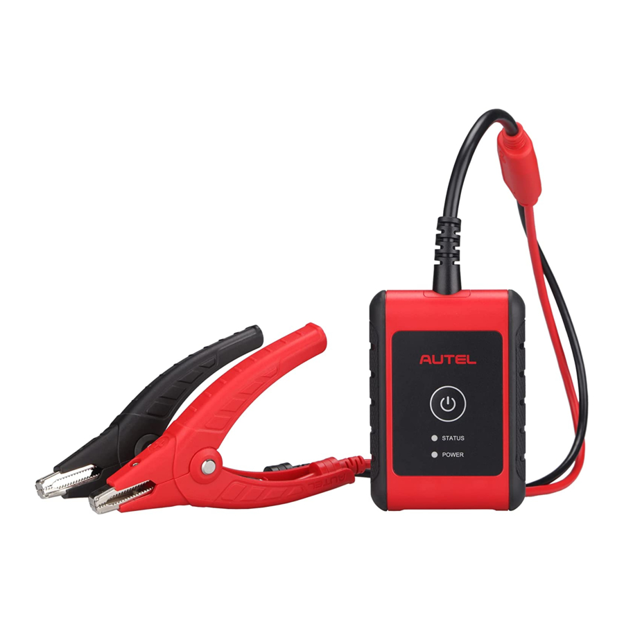
Page 9: Maxibas Bt508 Tester
2.1 MaxiBAS BT508 Tester 2.1.1 Function Description Figure 2-1 MaxiBAS BT508 1. Power Button 2. Status LED 3. Power LED 4. USB Port 5. Battery Clamp Cable... -
Page 10: Power Sources
Table 2-1 LED Description Color Description The tester is communicating via USB Flashing Green cable. Status The tester is communicating via Flashing Blue Bluetooth. Battery clamps are connected to the Flashing wrong battery terminals. Solid Green: tester powered on and the battery is sufficiently charged. -
Page 11: Technical Specifications
Internal Battery Pack The BT508 is powered via its internal rechargeable battery. AC/DC Power Supply — Using Power Adapter The tester can be powered from an electrical outlet using the AC/DC power supply. The AC/DC power supply also charges the internal battery pack. 2.1.3 Technical Specifications Item Description... -
Page 12: Maxivci V200P - Vehicle Communication Interface
2.2 MaxiVCI V200P — Vehicle Communication Interface 2.2.1 Function Description Flashlight Power Button Power LED Vehicle/Connection LED Vehicle Data Connector (16-pin) USB Port VCI LED Description Color Description The VCI is powered on and performing Yellow self-check. Power LED Green The VCI is ready for use. -
Page 13: Power Sources
2.2.2 Power Sources The VCI device can receive power from the following sources: Vehicle power AC/DC power supply Vehicle Power The VCI device operates on 6 or 12 Volt vehicle power, which receives power via the vehicle data connection port. The device powers on whenever it is connected to an OBD II/EOBD compliant data link connector (DLC). - Page 14 Item Description Weight 70.7 g (0.156 lb.) Built-in Battery 3.7 V Lithium Battery Light White LED...
-
Page 15: Getting Started
Getting Started Ensure that the unit is sufficiently charged. NOTE The images and illustrations depicted in this manual may differ slightly from those displayed on your device. The user interfaces for iOS & Android devices might be slightly different. This manual depicts screens from the Android version of the app. - Page 16 Log in with your registered email address and password. NOTE If you already have an existing Autel account, log in with your registered Autel account email and password. Pair the BT508 Pair the BT508 with the Battery Test app by scanning the QR code on the back of the tester or via Bluetooth pairing.
-
Page 17: Application Buttons
3.1.1 Application Buttons Button Name Description Tests batteries that are installed in a vehicle. In-vehicle test (See page 14.) Out-vehicle Tests batteries that are not installed in a vehicle. test (See page 27.) Battery Operation guide for battery change. change (See page 29.) Accesses the Battery reset function. -
Page 18: Connecting To A Battery
Corrosion on the battery terminals and dirt or acid on the case top. Clean the terminals and the case top using a wire brush and a mixture of water and baking soda. 3.2.2 Connecting to a Battery Press and hold the Lock/Power button to turn on the BT508. Connect the red clamp to the positive (+) terminal and the black clamp to the negative (–) terminal of the battery. -
Page 19: In-Vehicle Test
In-vehicle Test The in-vehicle test is used for testing batteries that are installed in a vehicle. An in-vehicle test includes the Battery test, Starter test, and Generator test, and determines the health status of the battery, the starter, and the generator, respectively. -
Page 20: Start The Test
4.1 Start the Test Select In-vehicle test on the Home screen. Figure 4-2 Sample Home Screen Home screen — displays six major functions of the BT508, including In-vehicle test, Out-vehicle test, Battery change, Battery reset, Diagnostics, and History. Navigation Button — displays Home screen, Mall, and Me. Via the Mall, the user can download the three software apps (Demo, Eobd and Battery Test) for free. -
Page 21: Vci Connection
4.1.1 VCI Connection Connect the VCI to the vehicle’s OBD II Data Link Connector (DLC). Tap the icon on the top-right corner to enter the VCI Manager menu. The device will automatically enable Bluetooth and start searching for available pairing units. The device’s name will appear on this menu as “Maxi”... - Page 22 Figure 4-3 Sample VCI Manager Screen Tap the icon to return to the previous screen. The mobile device will switch to the Vehicle information screen. The VCI button on the top right corner of the screen will display a green check mark, indicating the mobile device is connected to the VCI.
-
Page 23: Confirm Vehicle Information
4.1.2 Confirm Vehicle Information Figure 4-4 Sample Vehicle Information Screen Buttons Name Button Description After the VCI is connected to the device through the vehicle’s OBD II Data Link AutoVIN Connector (DLC), turn on the ignition. The vehicle’s VIN will automatically be recognized. Battery Tap to view the battery location diagram. - Page 24 The vehicle information will be automatically identified when vehicle communication is established. A Battery Information tab will appear from the bottom of the screen. Figure 4-5 Sample Battery Information Screen Tap the icon on the tab to return to the Vehicle information screen. Tap Battery Location on the bottom left corner of the screen and view the battery position diagram.
-
Page 25: Battery Test
4.2 Battery Test Table 4-1 Upper Toolbar Buttons Name Button Description Back Returns to the previous screen. Returns to the Diagnosis (or Diagnostics) Exit screen. Tap to enter the VCI Manager. The icon also Connection displays the connection status of the VCI. Displays the battery connection status. - Page 26 Figure 4-6 Sample Battery Information Screen 12. Follow the on-screen instructions, check the boxes and tap Start Testing. 13. Wait until the test is completed. The test results will appear as shown below:...
- Page 27 Figure 4-7 Sample Battery Test Result Screen 1. Process Buttons 2. Test Report 3. Function Buttons Process Buttons Tap any of the process buttons to advance to the corresponding test — battery test, starter test or generator test. A status icon will appear on the bottom right corner of the button, indicating the test results.
- Page 28 Table 4-2 Battery Test Results Result Repair Tip Good Battery Battery is good. Battery is in good condition. The battery should be Good & Recharge charged. Charge & Retest Charge the battery and retest. Bad Cell Replace the battery. Replace Battery Replace the battery.
-
Page 29: Starter Test
4.3 Starter Test 14. Follow the on-screen instructions to complete the test. Start the engine and let it idle. The test results will be displayed as follows: Figure 4-8 Sample Starter Test Results Screen Table 4-3 Starter Test Results Result Description Cranking Normal Starter is good. -
Page 30: Generator Test
4.4 Generator Test 15. Follow the on-screen instructions to complete the test. The test results will be displayed as follows: Figure 4-9 Sample Generator Test Results Screen... - Page 31 Table 4-4 Generator Test Results Result Description Charging Normal The generator is good. The belt linking the starter and the generator is loose; Output Too Low The cable linking the starter and battery is loose or corroded. The generator is not properly connected to the ground;...
-
Page 32: Out-Vehicle Test
Out-vehicle Test Out-vehicle test is used to test the condition of batteries that are not connected to a vehicle. This function aims to check the health status of the battery only. The compatible battery types and standards are as follows: Types: FLOODED, AGM, AGM SPIRAL, EFB, and GEL Standards: CCA, SAE, CA, EN, EN2, IEC, DIN, JIS, MCA, BCI, and GB 5.1 Test Procedure... -
Page 33: Test Results
The test results should be displayed in a few seconds. Figure 5-2 Sample Out-vehicle Test Screen 5.2 Test Results Icons are color-coded to indicate status. Result Description Good Battery Battery meets required standards. Battery is good, but low on charge. Fully charge the Good &... -
Page 34: Battery Change
Battery Change The Battery Change function guides you to replace the battery step by step. The battery replacement process includes Battery Type Suggestion, Preparation, Battery Replacement steps, New Battery Test and Battery Registration. 6.1 Replace the Battery Tap the Help button at the bottom of each screen to read all the help information carefully before operation, then follow the on-screen instructions to complete the battery replacement. - Page 35 To save the vehicle’s onboard data when the vehicle’s battery is removed or disconnected, we recommend using a memory saver (an optional accessory) to connect a spare battery to the vehicle. Figure 6-2 Sample New Battery Test Results Screen When the new battery test is completed, tap Next to automatically proceed to Auto Registration in the Battery Reset section.
-
Page 36: Battery Reset
Battery Reset The Battery Reset allows users to access the following functions: Auto registration (after battery replacement), BMS reset, Electric appliance reset, Special function and Battery usage history. Figure 7-1 Sample Battery Reset Main Menu Screen 7.1 Auto Registration (after battery replacement) Auto registration is often used after the successful installation of a new battery, including BMS reset and Electric appliance reset. -
Page 37: Bms Reset
7.1.1 BMS Reset The BMS feature enables you to register a new battery after battery replacement. The BMS Reset function varies by vehicle make. Please follow the on-screen instructions to perform the desired functions. Figure 7-2 Sample BMS Reset Screen After choosing the desired battery replacement registration, information of Scene, Condition, Influence, and Note will appear. -
Page 38: Special Functions
vehicle make. Please follow the on-screen instructions to perform the desired functions. Figure 7-3 Sample Electric Appliance Reset Screen 7.2 Special Functions The special functions vary by vehicle make. Functions other than battery reset are categorized as special functions. Please follow the on-screen instructions to perform the desired function. -
Page 39: Battery Usage History (Only For Bmw Vehicles)
Figure 7-4 Sample “Reset Closed-circuit Current Monitoring Cycle” Screen (BMW vehicles) 7.3 Battery Usage History (only for BMW vehicles) The Battery Usage History function will display the following three tests: SOC (State of Charge) in the last 5 days: monitors the SOC status and diagnoses the health status of the battery. - Page 40 All three test screens are comprised of three sections: Main view: displays data in a waveform or bar graph. Data description: provides brief descriptions of the test result. Suggestion: offers suggestions on existing problems. Figure 7-5 Sample SOC in the Last 5 Days Screen...
-
Page 41: Diagnostics
Diagnostics The application performs functional tests, retrieves vehicle diagnostic information such as trouble and event codes as well as capturing live data for various vehicle control systems including engine, transmission and ABS. There are two options available when accessing the Diagnostics section: Auto Scan —... - Page 42 Figure 8-1 Sample Auto Scan Screen 1. Progress Percentage — indicates the test progress 2. Main Section 3. Function Buttons Main Section Column 1 — displays the sequence numbers. Column 2 — displays the scanned systems. Column 3 — displays the diagnostic indicators describing test results. Indicators are defined as follows: Fault | #: Fault indicates fault code(s) detected;...
-
Page 43: Control Units
Column 4 — to perform further diagnosis or testing on a specific system item, tap the > button to the right of that item. A Function Menu screen should appear. Function Buttons A brief description of the operations of the Auto Scan function buttons are displayed in the table below. - Page 44 Figure 8-2 Sample Function Menu Screen The Function menu options may vary slightly by vehicle. The Function menu may include: ECU information Read codes Erase codes Live data Freeze frame...
-
Page 45: Ecu Information
To perform a diagnostics function: Establish communication with the test vehicle. Identify the test vehicle by selecting from the menu options. Select the Diagnostics section. Choose Auto Scan to locate a desired system or through menu- driven selections in Control Units. Select the desired diagnostics function from the Function menu. -
Page 46: Read Codes
8.2.2 Read Codes This function retrieves and displays the DTCs from the vehicle’s control system. The Read codes screen varies by each vehicle tested. Freeze frame data can be viewed if available (snowflake icon indicates data is available). Figure 8-4 Sample Read Codes Screen... -
Page 47: Erase Codes
Main Section Code section — displays the retrieved codes from the vehicle. Description section — describes the retrieved codes in detail. Status section — indicates the status of the retrieved codes. Snowflake icon — only appears when freeze frame data is available for viewing. -
Page 48: History
History This option stores records of test vehicle history, including battery tests and diagnostics. The diagnostics records also provide test results from previously- tested vehicles and enables the user to restart a diagnostic session by selecting record without the need to perform auto or manual vehicle selection. Figure 9-1 Sample Diagnostics Test Records Screen... -
Page 49: Mall
The Mall provides users with a quick access to the app’s built-in store for purchasing vehicle diagnostic packages. Please enter your Autel ID and link the MaxiBAS BT508 device to your account. Three vehicle software sets (Battery Test, Eobd and Demo) are free and available for the life of the tool. - Page 50 Tap the Mall button on the Home screen. A list of vehicle brands sorted by alphabet will display. The corresponding price of each app is displayed on the right side of the software. Tap the price of the desired app to view the detail screen, with more information about the app.
- Page 51 In this section, users have access to functions including Order Manager, Repair Reports, Delete Vehicle, Data Logging, VCI Manager, BAS Manager, Settings, and User Manual. Figure 11-1 Sample Me Screen The above functions are available only after registration.
-
Page 52: Order Manager
To complete registration: Tap the Register button on the Log in screen. Enter your email address. Tap the Verification code button and an email will be sent to your address with your unique verification code. Enter the verification code and your account password on the registration screen. -
Page 53: Delete Vehicle
This option allows you to delete vehicle files from the unit. 11.4 Data Logging The Data Logging option allows you to launch the Autel Support platform to view all recordings on the diagnostic system. The Data Logging option keeps all test records, whether submitted (Feedback) or not submitted (Not... -
Page 54: Vci Manager
Support platform. 11.5 VCI Manager VCI Manager is for connecting the MaxiBAS BT508 with a VCI device via Bluetooth. This option allows you to pair the tester with the VCI device, check the communication status, and upgrade the VCI firmware. -
Page 55: User Manual
Tap English to have the tool display measures in English units. Tips Reset Reset the tips feature to turn on the on-screen guidance when using your unit. 11.8 User Manual This option launches the User Manual for the MaxiBAS BT508. -
Page 56: Maintenance And Service
Maintenance and Service This chapter describes problems that you may encounter while using the MaxiBAS BT508. Battery usage and service information is also introduced. 12.1 Maintenance Instructions The following shows how to maintain your device, together with precautions to take. -
Page 57: Troubleshooting Checklist
Ensure the tool is being charged in a room of moderate temperature, not too hot or too cold. Contact technical support or your authorized Autel supplier if the unit or charger is damaged. C. When Bluetooth connection fails: ... - Page 58 DANGER The built-in Lithium-ion Polymer battery is factory replaceable only; incorrect replacement or tampering with the battery pack may cause an explosion. Do not use a damaged battery charger. Do not disassemble or open, crush, bend or deform, puncture or shred. ...
-
Page 59: Service Procedures
12.4.1 Technical Support If you have any question or problem on the operation of the product, please contact us. AUTEL NORTH AMERICA Phone: 1-855-AUTEL-US (288-3587) (855-288-3587) Monday-Friday 9am-6pm EST Website: www.autel.com Email: ussupport@autel.com ... - Page 60 AUTEL CHINA HQ Phone: 0086-755-2267-2493 (Monday-Friday, 9:00AM-6:00PM Beijing Time) Website: www.autel.com Email: support@autel.com Address: 7th, 8th and 10th floor, Building B1, Zhiyuan, Xueyuan Road, Xili, Nanshan, Shenzhen, 518055, China. AUTEL LATIN AMERICA Website: www.autel.com ...
-
Page 61: Repair Service
For technical assistance in other markets, please contact your local distributor. 12.4.2 Repair Service If it becomes necessary to return your device for repair, please download the repair service form from www.autel.com, and fill in the form. The following information must be included: ... -
Page 62: Compliance Information
Compliance Information FCC Compliance FCC ID: WQ8BATS-BT508 This device complies with part 15 of the FCC Rules. Operation is subject to the following two conditions: This device may not cause harmful interference, and This device must accept any interference received, including interference that may cause undesired operation. - Page 63 -- Increase the separation between the equipment and receiver. -- Connect the equipment into an outlet on a circuit different from that to which the receiver is connected. -- Consult the dealer or an experienced radio/TV technician for help. FCC Radiation Exposure Statement This equipment complies with FCC radiation exposure limits set forth for an uncontrolled environment.
-
Page 64: Warranty
Warranty Limited One Year Warranty Autel Intelligent Technology Corp., Ltd. (the Company) warrants to the original retail purchaser of this MaxiBAS battery tester, that should this product or any part thereof during normal consumer usage and conditions, be proven defective... - Page 65 IMPORTANT All contents of the product may be deleted during the process of repair. You should create a back-up copy of any contents of your product before delivering the product for warranty service.
Need help?
Do you have a question about the MaxiBas BT508 and is the answer not in the manual?
Questions and answers