Autel MaxiTPMS TS601 Manual
Hide thumbs
Also See for MaxiTPMS TS601:
- Instruction manual (80 pages) ,
- Operating manual (1 page) ,
- Instructions (1 page)
Table of Contents
Advertisement
Quick Links
Trademarks
®
Autel
, MaxiSys
®
MaxiCheck
are trademarks of Autel Intelligent Technology Corp., Ltd.,
registered in China, the United States and other countries. All other marks are
trademarks or registered trademarks of their respective holders.
Copyright Information
No part of this manual may be reproduced, stored in a retrieval system or
transmitted, in any form or by any means, electronic, mechanical, photocopying,
recording, or otherwise without the prior written permission of Autel.
Disclaimer of Warranties and Limitation of Liabilities
All information, specifications and illustrations in this manual are based on the
latest information available at the time of printing. Autel reserves the right to
make changes at any time without notice. While information of this manual has
been carefully checked for accuracy, no guarantee is given for the
completeness and correctness of the contents, including but not limited to the
product specifications, functions, and illustrations.
Autel will not be liable for any direct damages or for any special, incidental, or
indirect damages or for any economic consequential damages (including the
loss of profits).
IMPORTANT
Before operating or maintaining this unit, please read this manual carefully,
paying extra attention to the safety warnings and precautions.
For Services and Support:
pro.autel.com
www.autel.com
1-855-288-3587/1-855-AUTELUS (North America)
0086-755-86147779 (China)
support@autel.com
For technical assistance in all other markets, please contact your local
distributor.
®
®
, MaxiDAS
, MaxiScan
®
®
, MaxiTPMS
i
®
, MaxiRecorder
, and
Advertisement
Table of Contents

Related Manuals for Autel MaxiTPMS TS601


Summary of Contents for Autel MaxiTPMS TS601
- Page 1 Autel will not be liable for any direct damages or for any special, incidental, or indirect damages or for any economic consequential damages (including the loss of profits).
- Page 2 Safety Precautions and Warnings To prevent personal injury or damage to vehicles and/or the scan tool, read this instruction manual first and observe the following safety precautions at a minimum whenever working on a vehicle: ⚫ Always perform diagnosis or service in a safe environment. ⚫...
-
Page 3: Table Of Contents
CONTENTS ............AFETY RECAUTIONS AND ARNINGS 1 USING THE MANUAL ................1 ....................1 ONVENTIONS 2 GENERAL INFORMATION ................. 3 TPMS .................. 3 SYSTEM REVIEW TPMS L ..................3 EGISLATION TPMS T ................4 TALE IGHT TPMS ..................4 ENEFITS OF 3 TOOL INFORMATION ................ - Page 4 ................... 63 REEZE RAME I/M R ..............64 ETRIEVE EADINESS TATUS O2 M ..................66 ONITOR ................68 OARD ONITOR ..................69 OMPONENT ................ 70 EHICLE NFORMATION ..................71 ODULES RESENT 7 RKE & RF MONITOR ................73 8 REVIEW DATA ..................74 9 PRINT AND UPDATE ................
-
Page 5: Using The Manual
Using the Manual This manual contains device usage instructions. Some illustrations shown in this manual may contain modules and optional equipment that are not included on your system. Contact your sales representative for availability of other modules and optional tools or accessories. - Page 6 Hyperlinks Hyperlinks or links that take you to other related articles, procedures, and illustrations are available in electronic documents. Blue italic text indicates a selectable hyperlink and blue underlined text indicates a website link or email address link. Illustrations Illustrations used in this manual are samples, the actual testing screen may vary for each vehicle being tested.
-
Page 7: General Information
General Information TPMS system review A tire pressure monitoring system (TPMS) is an electronic system designed to monitor the air pressure inside the pneumatic tires on various types of vehicles. TPMS report real-time tire-pressure information to the driver of the vehicle, either via a gauge, a pictogram display, or a simple low-pressure warning light. -
Page 8: Tpms Tell-Tale Light
TPMS Tell-tale Light When diagnosing TPMS systems, you should understand what the TPMS tell-tale light means. When turning the ignition OFF to ON, the TPMS tell-tale should come on, and then go off, which indicates the system is working fine. If the light stays on, there would be a pressure problem. -
Page 9: Tool Information
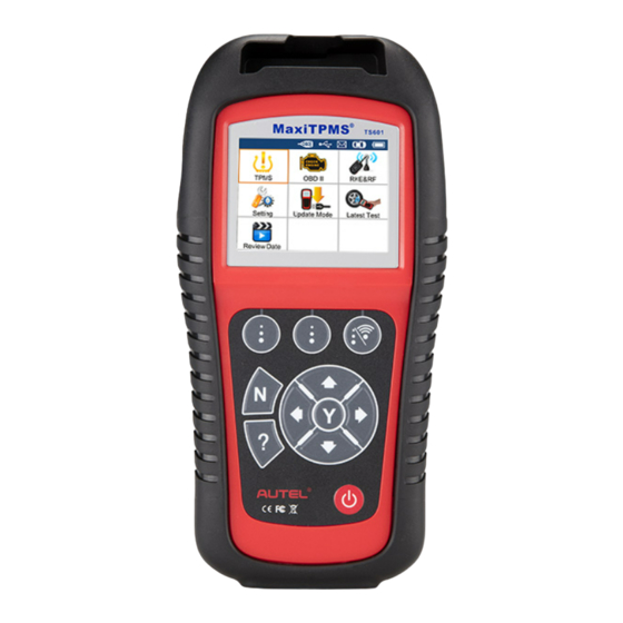
Tool Information Tool Description Figure 3-1 SENSOR SLOT – holds the MX-Sensor needs to be programmed. LCD DISPLAY – displays the menus and test screens. FUNCTION BUTTONS – corresponds with “buttons” on screen for executing commands. UP SCROLL BUTTON – moves up through menu and submenu items in menu mode. -
Page 10: Specifications
LEFT SCROLL BUTTON – when scrolling through a screen of data or text, moves to previous character and views additional information on previous screens if recorded data content covers more than one screen. HELP BUTTON – provides help information. POWER BUTTON – long press this button to turn on/off the tool; or, short press the button to return to Home screen. -
Page 11: Accessories
Storage Temperature: -20° C to 70° C (-4° F to 158° F) Dimensions: Length Width Height 37.7 mm (1.48”) 202.2 mm (7.96”) 106.7 mm (4.20”) Weight: 0.4 kg (0.88 lb.) Accessories OBD II Cable – provides power to tool and communicates between tool and vehicle. -
Page 12: Keyboard
Keyboard No solvents such as alcohol are allowed to clean the keypad or display. Use a mild nonabrasive detergent and a soft cotton cloth. Do not soak the keypad as the keypad is not waterproof. Battery Charging The TPMS tool has a 3.7 V built-in lithium-ion polymer rechargeable battery. There are two means of battery charging: ✓... -
Page 13: System Setting
Figure 3-2 System Setting The tool allows you to make the following adjustments and settings. Market: Selects the area of work, Europe or America. Language: Selects the desired language. Pressure Unit: Sets the pressure unit in kPa, Psi or Bar. Temperature Unit: Sets the temperature unit in degree Celsius or Fahrenheit. - Page 14 Figure 3-3 Market This function allows you to switch among the supported corresponding models for European and American areas. From System Setting screen, use the UP/DOWN scroll button and the LEFT/RIGHT scroll button to select Market, and press the Y button. From Market screen, use the LEFT/RIGHT scroll button to select the work area.
- Page 15 From System Setting screen, use the UP/DOWN scroll button and LEFT/RIGHT scroll button to select Language, and press the Y button. Use the UP/DOWN scroll button and LEFT/RIGHT scroll button to select the desired language and press the Y button to save your selection and return to previous menu.
- Page 16 Temperature Unit From System Setting screen, use the UP/DOWN scroll button and LEFT/RIGHT scroll button to select Temperature Unit, and press the Y button. From Temperature Unit screen, use the LEFT/RIGHT scroll button to select the desired unit of temperature. Figure 3-7 Press the Y button to save your settings and return to previous menu, or press the N button to exit without change.
- Page 17 Press the Y button to save your settings and return to previous menu, or press the N button to exit without change. ID Format From System Setting screen, use the UP/DOWN scroll button and LEFT/RIGHT scroll button to select ID Format, and press the Y button. From ID Format screen, use the LEFT/RIGHT scroll button to select the desired ID format.
- Page 18 Figure 3-10 Press the Y button to save your selection or the N button to exit without change. Wheels This function allows you to set sensor testing mode in All Wheels or One Wheel. From System Setting screen, use the UP/DOWN scroll button and LEFT/RIGHT scroll button to select Wheels, and press the Y button.
- Page 19 Duplicated.”. In One Wheel mode, the tool will not check the duplication of sensor ID. Power-off From System Setting screen, use the UP/DOWN scroll button and LEFT/RIGHT scroll button to select Power-off, and press the Y button. Press the UP/DOWN scroll button to increase or decrease the interval time for auto power-off, and then press the Y button to confirm your change or the N button to exit without change.
-
Page 20: Product Troubleshooting
Figure 3-13 About This function allows viewing of some important information such as serial number and software version number of the tool. From System Setting screen, use the UP/DOWN scroll button and LEFT/RIGHT scroll button to select About, and press the Y button; wait for the About screen to appear. - Page 21 Vehicle Linking Error A communication error occurs if the TPMS tool fails to communicate with the vehicle’s ECU (Electronic Control Unit) when running the diagnostic function. You need to do the following to check up: ✓ Verify that the ignition is ON. ✓...
-
Page 22: Tpms Check & Diagnostics
TPMS Check & Diagnostics ® The MaxiTPMS TS601 is a new generation TPMS diagnostic & service tool specially designed to activate all known OEM/Universal TPMS sensors, and provide users with direct access to the vehicle’s ECU through OBD II connection, thus allowing users to reprogram sensor IDs, retrieve/clear TPMS DTCs, read live data and perform special functions, helping technicians to quickly find out faulty TPMS and turn off MILs. - Page 23 Figure 4-1 Observe the menu title and use the UP/DOWN scroll button to select by model and year to identify the vehicle being tested. ⚫ The selected vehicle is remembered by the tool when a test is commenced. Select by Model: Figure 4-2 Select by Year:...
- Page 24 Figure 4-3 For some vehicles an option screen will show up to let users choose between 4 Wheels and 5 Wheels test mode. Figure 4-4 ⚫ Depending on the test mode (All Wheels or One Wheel), results are displayed in different manners. All Wheels Mode In this mode, the screen will display as below (Figure...
- Page 25 Figure 4-5 Figure 4-6 The tool will do TPMS test in a sequence of FL (Front Left), FR (Front Right), RR (Rear Right), LR (Rear Left) and SPARE, if the vehicle has the option for the spare. Or, you can use the UP/DOWN or LEFT/RIGHT scroll button to move to the desired wheel for testing.
- Page 26 Under All Wheels mode, the tool can save up to 5 TPMS sensor data records at each time. Press the UP/DOWN or LEFT/RIGHT scroll button to turn over data screens while viewing. If more than five records are stored, the latest record will overwrite the oldest record. One Wheel Mode In this mode the screen will show as below (Figure...
- Page 27 Under One Wheel mode, the tool can save up to 10 TPMS sensor data records at each time. Select the wheel icon and press Y button to view all sensors’ information. Press the UP/DOWN and LEFT/RIGHT scroll button to turn over data screens while viewing. If more than ten records are stored, the latest record will overwrite the oldest record.
- Page 28 ⚫ If the TPMS sensor requires a magnet, place the magnet over the stem and then place the tool alongside the stem, and press the TEST button. Figure 4-10 ⚫ If the TPMS sensor requires tire deflation (of the order of 10 psi), then deflate the tire and place the tool alongside the stem while pressing the TEST button.
- Page 29 Figure 4-12 ⚫ Sensor activation can be aborted at any time by pressing the N button. When the activation is aborted, the screen will return to the previous menu. ⚫ By pressing the Y button, you may review information of all sensors tested.
- Page 30 [ID-H/D] – shows sensor ID data. [kPa/Psi/Bar] – indicates tire pressure. [° C/° F] – indicates tire temperature. [BAT] – indicates battery condition. [Mode] – defines tire sensor working mode or status. [Modulation] – indicates sensor signal amplitude. NOTE Different ID format, pressure and temperature units will display at the title bar according to the device’s system setting, please refer to System Setting on page 9 for detailed instruction.
-
Page 31: Tpms Relearn
Figure 4-16 If user is going to retest the sensor, a prompt will come up asking for your confirmation. Figure 4-17 Select Yes to delete all test records and enter test mode. Or select No to reserve the previous data and check the remaining untested sensors. - Page 32 Setting. Follow the same process in TPMS Sensor Check to enter the activation screen. Use the UP/DOWN scroll button or LEFT/RIGHT scroll button to select the TPMS Relearn function on the upper right corner of the screen. Figure 4-18 The tool will display a function screen as below. Use the UP/DOWN scroll button to select TPMS Diagnosis or TPMS Sensor Information, and press the Y button to continue.
- Page 33 The TPMS Diagnosis option allows user to write IDs to vehicle, read IDs from vehicle, read/clear TPMS codes, read TPMS live data, perform active test and special functions. ⚫ The TPMS Diagnosis function varies by the vehicle being tested. NOTE In this manner, the scan tool will communicate with the vehicle being tested.
- Page 34 Figure 4-21 The tool will display the sensor IDs and positions for your confirmation. Select Yes to register the ID in vehicle ECU, or No to exit. Figure 4-22 Once the sensor IDs are successfully written, a confirm screen will show up.
- Page 35 If there are untested sensors in the vehicle, the writing ID process cannot proceed. The tool will display a warning message as below. In this case, follow the sensor check procedure to activate all sensors in vehicle and register sensor IDs again. Figure 4-24 NOTE If duplicate IDs present, the writing ID process cannot proceed.
- Page 36 Read Codes From the TPMS Diagnosis Menu, use the UP/DOWN scroll button to select the Read Codes, and press the Y button. The tool will display TPMS DTCs retrieved from the vehicle’s ECU for your viewing. Select Save to store data for future review, or press N button to exit without saving.
- Page 37 Figure 4-28 Live Data This function not only allows you to read the live data but also lets you record live data for later review. From the TPMS Diagnosis Menu, use the UP/DOWN scroll button to select Live Data, and press the Y button. All Data From the Live Data menu, use the UP/DOWN scroll button to select All Data and press the Y button.
- Page 38 Figure 4-30 ⚫ Press the corresponding FUNCTION button Save to store the retrieved live data for later playback or printing. ⚫ Press the corresponding FUNCTION button Stop Save to stop saving data and resume live sensor data retrieving (Figure 4-31). ⚫...
- Page 39 Figure 4-32 Figure 4-33 ⚫ Press the corresponding FUNCTION button Text or the N button to return to previous screen. Figure 4-34 Custom List To retrieve customized live sensor data, use the UP/DOWN scroll button to select Custom List from Live Data and press the Y button (Figure 4-29).
- Page 40 the corresponding FUNCTION button Select. Figure 4-35 ⚫ The Selected items are marked with ticks on the left. ⚫ The number on the right indicates sequence of the selected item. ⚫ Press the corresponding FUNCTION button Clear to unselect the items, or press the corresponding FUNCTION button Select All/Clear All to select or unselect all items (Figure...
- Page 41 From Active Test Menu, use the UP/DOWN scroll button to select Flat Tire Warning function (Figure 4-36). Press the corresponding FUNCTION button ON or OFF to check whether the TPMS warning lamp on the vehicle is turning on or off. Figure 4-37 Press the N button to return to the previous menu.
- Page 42 Figure 4-38 The tool displays a message for your confirmation. Select OK to continue and Cancel to exit. Figure 4-39 Press the corresponding FUNCTION button “ON” or “OFF” to turn ON/OFF the TPMS on the vehicle. Figure 4-40 Press the corresponding FUNCTION button “Back” to return to the previous screen.
-
Page 43: Audit Report
ECU Part Number To retrieve ECU part number, use the UP/DOWN scroll button to select ECU Part Number function item from the TPMS Diagnosis Menu (Figure 4-21). The ECU part number will be displayed once it’s successfully retrieved. Press the corresponding FUNCTION button Save to store for later playback and printing. - Page 44 Figure 4-42...
-
Page 45: Tpms Sensor Programming
The scan tool is easy-to-use with a proven efficiency and guaranteed accurate results. NOTE Programming function will only work with Autel’s MX-Sensor. Currently, there are two models available: Clamp-in Sensor and Snap-in Sensor, both with two types, one in orange color with 433MHz frequency, and one in dark gray color with 315MHz frequency. - Page 46 Figure 5-1 Observe the menu option and use the UP/DOWN scroll button to select by model and year to identify the vehicle being tested. NOTE Please pay attention to the frequency used in the vehicle. Refer to the original sensor information for the exact frequency. ⚫...
- Page 47 Select by Year: Figure 5-3 For some vehicles (like Chrysler), an option screen will show up allowing users to choose between 4 Wheels and 5 Wheels test mode before accessing the activation screen. Figure 5-4 ⚫ Depending on the test mode (All Wheels or One Wheel), results are displayed in different manners.
- Page 48 Figure 5-5 NOTE The MX-Sensor icon on the lower right corner will not appear if the TPMS Sensor Programming is not supported by the selected vehicle. Use the UP/DOWN scroll button to select the wheel which needs to be programmed. Figure 5-6 Use the UP/DOWN scroll button to select Auto Create to create a new random sensor ID.
- Page 49 Figure 5-7 Insert the correct MX-Sensor into the sensor slot as displayed below: Figure 5-8 NOTE Please pay attention to the MX-Sensor type displayed in the screen and insert the correct MX-Sensor. Inserting incorrect MX-Sensor will cause programming failure. Press the Y button to write in the new created sensor ID to the MX-Sensor, and the screen will show as below (Figure 5-9), or the N...
- Page 50 Figure 5-9 Figure 5-10 If programming failed, the screen will show as below, in this case, please perform programming function again. Figure 5-11 After programming is finished, a series of beep sound will be heard and the tool will display the data details such as the sensor ID, the temperature and the battery voltage after testing the new programmed MX-Sensor.
- Page 51 Press OK to return to the previous screen, and a sensor mark will appear on the right side of the screen, indicating the wheel sensor has been programmed. Figure 5-13 The Programmed option is available when selecting the programmed wheel sensor. Select “Programmed” to reprogram the wheel sensor with the same ID if necessary.
- Page 52 Figure 5-15 Use the UP/DOWN scroll button to select Auto Create to create a new random sensor ID. Figure 5-16 Insert the correct MX-Sensor into the sensor slot as displayed below: Figure 5-17 NOTE Please pay attention to the MX-Sensor type displayed in the screen and insert the correct MX-Sensor.
- Page 53 Press the Y button to write in the new created sensor ID to the MX-Sensor and the screen will show as below (Figure 5-18). If an error prompts, please keep the MX-Sensor to be programmed away from other MX-Sensor (Figure 5-19).
-
Page 54: Manual Create
After programming is finished, a series of beep sound will be heard and the tool will display the data details such as the sensor ID, the temperature and the battery voltage after testing the new programmed MX-Sensor. Figure 5-21 After all required MX-Sensor is programmed, please switch to All Wheels Setting and select Write IDs to Vehicle in Relearn function, refer to TPMS Relearn... - Page 55 Figure 5-22 Figure 5-23 Use the UP/DOWN scroll button and the LEFT/RIGHT scroll button to select the character and press the Y button to confirm. Figure 5-24 Use the left FUNCTION button to select Backspace to remove the entered character. Use the middle FUNCTION button to select Pre. to move the cursor to the previous character.
-
Page 56: Copy By Obd
Figure 5-25 NOTE Different sensor from manufacturer may have different ID character length limit. The scan tool will automatically recognize the OEM sensor ID character length, and prompt a message when entered character length is out of limitation. Figure 5-26 Insert the correct MX-Sensor and press the Y button to start programming or the N button to exit. -
Page 57: Copy By Activation
NOTE This function is not available under One Wheel mode. Follow the steps in Auto Create to select MX-Sensor to enter the Programming function. The OBD mark will appear on the right side of the screen (Figure 5-27). After selecting the specific wheel and pressing the Y button, the “Copy by OBD”... - Page 58 Figure 5-29 Select MX-Sensor icon and a trigger mark will appear on the right side of the screen. Figure 5-30 Use the UP/DOWN scroll button to select the corresponding wheel, press the Y button. Select Copy by Activation, insert the correct MX-Sensor into the sensor slot, and then press the Y button to start programming the retrieved sensor information to the MX-Sensor.
- Page 59 One Wheel Mode From the activation screen, press the TEST button to trigger the original sensor. You can use the LEFT/RIGHT button to select the specific tire to be triggered. When the information is retrieved, a series of beep sound will be heard and the sensor information will display. Figure 5-32 Select MX-Sensor icon and press the Y button, and then select Copy by Activation in the next screen.
- Page 60 Figure 5-34 NOTE In One Wheel mode, the tool can save at most 10 triggered sensors’ information each time. Please do not use the MX-Sensors with the same ID in the same vehicle. In All Wheels mode, if you had successfully performed both the Read IDs from Vehicle function and the activation function, the screen may show as below.
- Page 61 NOTE For the vehicles not supported by Relearn function, please select the “Manual Create” option to enter the original sensor ID manually, or trigger the original sensor at the activation screen to get the sensor information, before programming the MX-Sensor.
-
Page 62: Obd Ii Diagnostics
OBD II Diagnostics The OBD II Diagnostics function is a fast-access option that allows you to carry out a quick test on the engine system of OBD II-compliant vehicles. When more than one vehicle control module is detected by the scan tool, you will be prompted to select the module where the data may be retrieved. -
Page 63: Read Codes
your local distributor or our technical supports. View a summary of system status (MIL status, DTC counts, Monitor status) on screen. Figure 6-1 ⚫ If more than one module is detected, you will be prompted to select a module before testing. Figure 6-2 ⚫... - Page 64 Figure 6-3 Use the UP/DOWN scroll button to select Stored Codes, Pending Codes or Permanent Codes from the Read Codes menu and press the Y button. Figure 6-4 A screen of trouble codes will appear. If more than one DTC is found, use the UP/DOWN scroll button to check all the codes.
-
Page 65: Erase Codes
Erase Codes This function is performed with key on engine off (KOEO). Do not start ⚫ the engine. Use the UP/DOWN scroll buttons to select Erase Codes from Diagnostics Menu and press the Y button (Figure 6-3). A confirm screen will show up. Press the corresponding FUNCTION button Yes to continue;... - Page 66 Wait a few seconds while the scan tool validates the PID MAP. Figure 6-8 Complete List To view complete set of data, use the UP/DOWN scroll button to select Complete List from Live Data menu and press the Y button. Figure 6-9 Use the UP/DOWN scroll button to select a specific item or use the LEFT/RIGHT scroll button to turn to next page.
-
Page 67: Freeze Frame
Custom List To view customized PID data, use the UP/DOWN scroll button to select Custom List from Live Data menu and press the Y button (Figure 6-9). Use the UP/DOWN scroll button to move to the desired item and press the corresponding FUNCTION button Select to choose. -
Page 68: Retrieve I/M Readiness Status
Wait a few seconds while the scan tool validates the PID MAP. Use the UP/DOWN scroll button to select a specific item or use the LEFT/RIGHT scroll button to turn to next page. Figure 6-13 If there is no available freeze frame data, an advisory message “No freeze frame data stored!”... - Page 69 Use the UP/DOWN scroll button to select I/M Readiness from Diagnostic Menu and press the Y button (Figure 6-3). Wait a few seconds while the scan tool validates the PID MAP. If the vehicle supports both types of tests, then both types will be shown on the screen for selection.
-
Page 70: O2 Monitor Test
Figure 6-16 Use the UP/DOWN scroll button for more PIDs if additional information is available for more than one page. Or use the LEFT/RIGHT scroll button to view PIDs in the previous/next page. Press the N button to return to previous menu. O2 Monitor Test Use the UP/DOWN scroll button to select O2 Monitor Test from Diagnostic Menu and press the Y button... - Page 71 Figure 6-18 Select a specific item and press the Y button to view test value, maximum value, minimum value, and determine if it is OK. Figure 6-19 Press the corresponding FUNCTION button Save to store to Review Data for later playback and print or press the N button to return to previous menu.
-
Page 72: On-Board Monitor Test
On-Board Monitor Test Use the UP/DOWN scroll button to select On-Board Monitor Test from Diagnostic Menu and press the Y button (Figure 6-3). Wait a few seconds while the scan tool validates the PID MAP. Select the vehicle make and press the Y button (If you have selected the vehicle before, the Vehicle Manufacturer screen would not appear again). -
Page 73: Component Test
Figure 6-23 Press the N button to return to previous menu. Component Test Use the UP/DOWN scroll button to select Component Test from Diagnostic Menu and press the Y button (Figure 6-3). Wait for the scan tool to display the Component Test menu. Figure 6-24 If the test has been initiated by the vehicle, a confirmation message will be displayed on the screen. -
Page 74: View Vehicle Information
Figure 6-25 ⚫ If the test has not been successfully initiated by the vehicle, a message “LINKING ERROR” shows up. Make sure the tool and DLC are connected securely. ⚫ Some vehicles do not allow scan tools to control vehicle systems or components. -
Page 75: Modules Present
Figure 6-27 ⚫ If the vehicle does not support this mode, a message shows on the display warning that the mode is not supported. From Vehicle Info. menu, use the UP/DOWN scroll button to select Vehicle ID Number and press the Y button. Figure 6-28 Follow the same procedures to retrieve Calibration ID, Calibration Verification No., In-use Performance Tracking and ECU Name. - Page 76 Figure 6-29 Press the corresponding FUNCTION button Save to store the modules data to Review Data, or press the N button to exit.
-
Page 77: Rke & Rf Monitor
RKE & RF Monitor Today's keyless remotes – also known as key fobs – make life easier. But when your key fob stops working or starts to perform sporadically, it will be particularly frustrating. Check your key fob to make sure it is in top condition so it will work when you really need it. -
Page 78: Review Data
Review Data The Review Data function allows user to view and print out saved data of the latest TPMS diagnostic recordings and all diagnostic data retrieved from the ECUs of the OBD II-compliant vehicles by the service tool. Use the UP/DOWN and LEFT/RIGHT scroll button to select Review Data from Main Screen (Figure 3-1), and wait for the review data menu to... - Page 79 Figure 8-3 Print – select this function to print out the data on screen. For ⚫ detailed instructions, refer to Print Data on page 76. ⚫ Delete – use the RIGHT scroll button to delete the selected data. ⚫ Delete All – use the LEFT scroll button to delete all data on the screen.
-
Page 80: Print And Update
Print and Update To print out retrieved data or update software, you will need the followings: ✓ TS601 tool with SD card inserted ✓ Mac-based or Windows-based PC or laptop with USB ports ✓ USB cable Print Data The Print Data function allows printing out data retrieved by the service tool by connecting the scan tool to a PC or laptop with the USB cable supplied. -
Page 81: Software Update
Then you could download software, update online, retrieve information and get warranty service. NOTE Prior to registration, please confirm your network is working properly. Visit our website http://pro.autel.com. If you already have an Autel account, Sign In with your account ID and... - Page 82 If you are a new member to Autel, click on the Create Autel ID button on the left side of the screen to create an ID. Enter the required information in the input fields, and click the Get Verification Code button to get a verification code for email validation.
- Page 83 In the Update window, select the items you want to install. Usually, you should install all available updates. Figure 9-3 Generally there are two ways to update programs: Batch Update Select the programs that you would update by clicking on the check boxes next to those items.
- Page 84 Check the updating process by observing the upper left progress bar [Downloads] and upper right progress bar [Installs]. You may also find progress information in the Status column of updated items. Anytime you could click the Pause button in the line to suspend this progress.
- Page 85 Figure 9-4 ⚫ Click on OK to delete the program(s) selected, or on Cancel to cancel the action. ⚫ The deleted program will automatically add to the end of program list in the Update page in case you would like to install again.
-
Page 86: Compliance Information
Compliance Information FCC COMPLIANCE FCC ID: WQ83017501601 This device complies with Industry Canada’s licence-exempt RSSs. Operation is subject to the following two conditions: This device may not cause harmful interference. This device must accept any interference received, including interference that may cause undesired operation. Cet appareil est conforme aux CNR exempts de licence d’Industrie Canada. - Page 87 – Increase the separation between the equipment and receiver. – Connect the equipment into an outlet on a circuit different from that to which the receiver is connected. – Consult the dealer or an experienced radio/TV technician for help. Changes or modifications not expressly approved by the party responsible for compliance could void the user’s authority to operate the equipment.
-
Page 88: Warranty And Service
Warranty and Service Limited One Year Warranty Autel Intelligent Technology Corp., Ltd. (the Company) warrants to the original retail purchaser of this MaxiTPMS Diagnostic Device that should this product or any part thereof during normal usage and under normal conditions be proven defective in material or workmanship that results in... -
Page 89: Service And Support
Service and Support If you have any questions regarding the product, please contact one of our offices in your region. AUTEL NORTH AMERICA ⚫ Phone: 855-AUTEL-US (855-288-3587) Monday-Friday 9am-6pm ⚫ Website: www.autel.com, www.maxitpms.com ⚫ Email: ussupport@autel.com... - Page 90 ⚫ Address: Office 103, Building 3845, International Business Park, Veracruz, Panamá Pací fico, Panamá AUTEL AUSTRALIA ⚫ Phone: 03 9480 2978 / +61 476293327 ⚫ Website: www.autel.com.au, www.maxitpms.com ⚫ Email: sales@autel.com.au ⚫ Address: 155 Islington Street, Melbourne, Collingwood, VIC For technical assistance in other markets, please contact your local selling...
Need help?
Do you have a question about the MaxiTPMS TS601 and is the answer not in the manual?
Questions and answers