
Related Manuals for Meinberg microSync HR701/DC


Summary of Contents for Meinberg microSync HR701/DC
- Page 1 TECHNICAL REFERENCE microSync HR701/DC January 7, 2022 Meinberg Funkuhren GmbH & Co. KG...
-
Page 3: Table Of Contents
4.11 Return of Electrical and Electronic Equipment ......5 microSync HR701/DC - Connectors GPS Antenna . - Page 4 10 Technical Appendix: GPS Antenna + Accessories 10.1 Antenna Cable ..........10.2 Antenna Short Circuit .
-
Page 5: Imprint
1 Imprint 1 Imprint Meinberg Funkuhren GmbH & Co. KG Lange Wand 9, 31812 Bad Pyrmont, Germany Phone: + 49 (0) 52 81 / 93 09 - 0 Fax: + 49 (0) 52 81 / 93 09 - 230 Website: https://www.meinbergglobal.com... -
Page 6: Microsync Introduction
2 microSync Introduction The microSync is Meinberg’s versatile and powerful synchronization solution in a compact design. Depending on customer requirements, the microSync system is available with familiar input and output signals, such as PPS (pulse per second), Time Code AM and Time Code DCLS and programmable pulses, as well as with industry-specific signals such as Blackburst, DARS, Word Clock, etc. -
Page 7: Technical Data Microsync Housing
3 Technical data microSync housing 3 Technical data microSync housing Mechanical Data Enclosure type 9.5" (half-rack), 1U Enclosure material steel Weight incl. mounting bracket 2.2 kg (4.85 lbs) Environmental Requirements Temperature Range (Operation) 0 ... 50 C (32 ... 122 F) Temperature Range (Storage) -20 ... - Page 8 Dimensions: Front view 482.6 mm [ 19 inch ] 465.1 mm [ 18.31 inch ] 43.7 mm 31.8 mm [ 1.72 inch ] [ 1.25 inch ] Top view 223 mm [ 19 inch ] 251 mm [ 9.88 inch ] 236 mm [ 9.29 inch ] Date: January 7, 2022...
-
Page 9: Important Safety Information
4 Important Safety Information 4 Important Safety Information 4.1 Important Safety Instructions and Protective Measures The following safety instructions must be observed whenever the device is being installed or operated. Failure to observe safety instructions and other special warnings and operating instructions in the product manuals constitutes improper usage and may violate safety standards and the manufacturer’s requirements. -
Page 10: Used Symbols
4.2 Used Symbols The following symbols and pictograms are used in this manual. Pictograms are used in particular to indicate potential hazards in all hazard categories. Symbol Beschreibung / Description IEC 60417-5031 Gleichstrom / Direct current IEC 60417-5032 Wechselstrom / Alternating current IEC 60417-5017 Erdungsanschluss / Earth (ground) terminal IEC 60417-5019... - Page 11 The product manuals are provided on a USB flash drive delivered with the system. The manuals can also be downloaded from the Meinberg website at https://www.meinbergglobal.com, where you can enter your system name into the search box at the top of the page to find the relevant manual. Alternatively, contact Meinberg Support for further assistance.
-
Page 12: Security During Installation
4.3 Security during Installation WARNING! Preparing for Commissioning This built-in unit, has been designed and examined according to the requirements of the standard IEC 62368-1 "Audio/video, information and communication technology equipment - Part 1: Safety requirements". When the built-in unit is used in a terminal (e.g., housing cabinet), additional requirements according to Standard IEC 62368-1 must be observed and complied with. - Page 13 4 Important Safety Information Connecting Data Cables During a thunderstorm, data transmission lines must not be connected or disconnected (risk of lightning). When wiring the devices, the cables must be connected or disconnected in the order of the arrangement described in the user documentation accompanying the device. Always attach all cables to the plug during connection and removal.
-
Page 14: Safety Information On Sfp Modules
fiber optic or electrical connection. The safety information below must be read and heeded before installing an SFP module in a Meinberg device, before setting up a Meinberg device equipped with SFP modules for use, or before performing maintenance on such a Meinberg device. -
Page 15: Connection Of Protective Earth Conductor/Grounding
4 Important Safety Information 4.5 Connection of Protective Earth Conductor/Grounding ATTENTION! In order to ensure that the device can be operated safely and to meet the requirements of IEC 62368-1, the device must be correctly connected to the protective earth conductor via the protective earth connection terminal. -
Page 16: Safety During Maintenance
Opening the device or individual device components in an unauthorized fashion may also expose the user to considerable risks and invalidate your warranty. Meinberg Funkuhren accepts no liability for consequences arising from such unauthorized actions. Danger from moving parts—do not touch moving parts. - Page 17 The battery is used to power components such as the RAM and the reserve real-time backup clock for the reference clock. If the battery voltage drops below 3 V DC, Meinberg recommends having the battery replaced. If the battery voltage drops below the specified minimum, the following behavior may be observed in the reference clock: •...
-
Page 18: Cleaning And Care
4.9 Cleaning and Care ATTENTION! Never clean the device using liquids! Water ingress is a significant safety risk for the user (e.g., electric shock). Liquids can cause irreparable damage to the electronics of the device! The ingress of liquids into the device chassis may cause short circuits in the electronic circuitry. Only clean with a soft, dry cloth. -
Page 19: Return Of Electrical And Electronic Equipment
When disposing of your old equipment, please use the national return or collection systems available to you. Alternatively, you may contact Meinberg, who will provide further assistance. The return of electronic waste may not be accepted if the device is soiled or contaminated in such a way that it potentially presents a risk to human health or safety. -
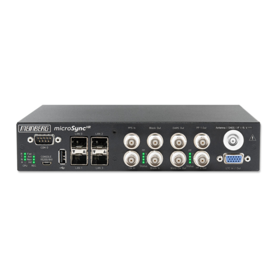
Page 20: Microsync Hr701/Dc - Connectors
5 microSync HR701/DC - Connectors 5.1 GPS Antenna Antenna input GPS180: Antenna circuit electrically isolated Dielectric strength: 1000 V Mixed frequency Reference clock to antenna (GPS-converter): 10 MHz IF frequency Antenna (GPS-converter) to reference clock: 35.4 MHz 1) these frequencies are transfered via the antenna cable... -
Page 21: Ltc/Gpio
5 microSync HR701/DC - Connectors 5.2 LTC/GPIO Signal: LTC-Reader (25 fps) Signal level: TTL; 2,5 V (MARK/SPACE) at 50 Ohm Pin Assignment: LTC out - LTC symmetric Lo Pot. Output LTC_out + LTC symmetric HI Pot. Output LTC_in + LTC symmetric HI-Poti. Input LTC in - LTC symmetric Lo Pot. -
Page 22: Status Leds - Vsg Signals
5.4 Status LEDs - VSG Signals Status indicator LED St: Status of the internal VSG LED In: Synchronization status LED A: Status of the blackburst output LED B: Status of the LTC output The status messages of the LEDs result as follows:. LED St: Blue During initialization... -
Page 23: Dars Input
5 microSync HR701/DC - Connectors 5.5 DARS Input Output signal: DARS Signal level: TTL; 2.5 V into 75 ohms Signal type: Base frequencies: 44.1 kHz and 48 kHz Connection type: BNC female connector Cable: Coaxial cable, shielded 5.6 Word Clock Output... -
Page 24: Blackburst Input
5.7 Blackburst Input Input Signal Black Burst (PAL) Input with VITC Reader Input with Prescaler mode (Frequency only) Signal level: 300 mV into 75 ohms (unbalanced) Time Code Formats: PAL SMPTE259M / ITU-R BT.470-6 SMPTE12M-1 / SMPTE ST309M Connection type: BNC female connector Cable: Coaxial cable, shielded... -
Page 25: Status Leds - Input Signals
5 microSync HR701/DC - Connectors 5.9 Status LEDs - input signals Status indicator LED B: Status of the blackburst input signal. LED L: Status of the LTC input signal LED C: Status of the Word Clock input signal LED P: Status of the PPS input signal The status messages of the LEDs are as follows:. -
Page 26: Pulse Per Second Input
5.10 Pulse Per Second Input Input signal PPS (pulse per second) Signal level: Pulse lenght: 5 s, active high Connection type: BNC, female Cable: Coaxial cable, shielded 5.11 Word Clock Input Input signal: Word Clock Input with programmable frequency range Signal level: Frequency range: 1 kHz - 10 MHz Cable:... -
Page 27: Usb Interface
5 microSync HR701/DC - Connectors Available SFP Modules SFP Tranceivers Recommended and Tested by Meinberg Output Type Manufacturer Designation Multi Mode: Avago AFBR-5710PZ Finisar FTLF8524P3BNL Single Mode: Avago AFCT-5710PZ Finisar FTLF1318P3BTL RJ-45: Avago ABCU-5740RZ Finisar FCLF8521P2BTL WARNING! Prevention of Eye Injuries Fiber optic SFP modules that are not compliant with the definition of a Ÿ... -
Page 28: Rs-232 Comx Timestring
5.14 RS-232 COMx Timestring Data transfer: serial Baudrate/framing: 19200 / 8N1 (default) Time-string: Meinberg Standard (default) Assignment: Pin 2: RxD (receive) Pin 3: TxD (transmit) Pin 5: GND (ground) Connector: 9pin D-SUB male Cable: data cable (shielded) PC connector 1:1... -
Page 29: Status Indicators - Cpu And Receiver
5 microSync HR701/DC - Connectors 5.15 Status Indicators - CPU and Receiver CPU: —————————————————————————– R (Receiver) green: The reference clock (e.g. build-in GPS180) provides a valid time red: the reference clock does not provide a valid time T (Time Service) -
Page 30: Power Supply And Protective Earth Connection
, always follow the input voltage range specifications above. The desktop AC adapter, included in the scope of delivery, is approved by Meinberg for powering the microSync . Please use this power adapter for the power supply of the microSync system. - Page 31 5 microSync HR701/DC - Connectors Other specifications: Cable length (output): 1800 mm DC connector (right angle): (Ø 5.5/Ø 2.5) L10.5 mm AC input: IEC320/C14 Approval: IEC62368-1, UL62368-1, EN62368-1 For more detailed information about the desktop AC adapter, download the manufacturer’s datasheet: https://www.meinbergglobal.com/download/docs/other/Datasheet-TRH50A.pdf...
-
Page 32: Gnss Satellite Navigation
6 GNSS Satellite Navigation The GPS180 satellite receiver clock is designed to provide users with a high-precision time & frequency refer- ence. This system, which can draw information from the satellites of the Russian GLONASS (GLObal NAvigation Satellite System), American GPS (Global Positioning System), European Galileo, and Chinese BeiDou systems, is defined by its high precision and the ability to use it at any time, anywhere in the world. -
Page 33: Time Zones And Daylight Saving Time
6 GNSS Satellite Navigation 6.1 Time Zones and Daylight Saving Time GPS System Time is a linear timescale that was synchronized with the international UTC timescale (Coor- dinated Universal Time) when the satellite system became operational in 1980. Since it has entered service, however, several leap seconds have been introduced to the UTC timescale to adjust UTC time to irregularities in the Earth’s rotation. -
Page 34: Installation Of The Gps Antenna
7 Installation of the GPS Antenna WARNING! Do not mount the antenna without an effective fall arrester! Danger of death from falling! - Ensure that you work safely when installing antennas! - Never work without an effective fall arrester! WARNING! Do not work on the antenna system during thunderstorms! Danger of death from electric shock! - Do not carry out any work on the antenna system or the antenna cable... - Page 35 Type-N (Male) If installed in a waterproof housing, the MBG S-PRO Type-N (Female) can be installed outdoors. However, Meinberg recommends installing the surge protector indoors—as closely to the entrance point of the antenna cable as possible—in order to minimize the risk of surge damage (such as that caused by lightning strike).
- Page 36 Grounding Conductor To ground the antenna cable, connect the surge to Grounding Busbar protector to a grounding busbar using a grounding Conductor of diameter approx. conductor (see illustration). 1,5 mm, attached to surge protector Once installation is complete, connect the other As short as possible end of the antenna cable to the surge protector female connector.
- Page 37 7 Installation of the GPS Antenna Optional Antenna Splitter Multiple receivers can be connected to one antenna using the antenna splitter. When doing so, be aware that the total distance, comprising the cable from the antenna to the splitter, and from there to the receiver, must not exceed the maximum cable length.
-
Page 38: Starting Of Operation
The software is delivered on the USB stick included in the scope of delivery and does not need to be in- stalled or copied on the PC. The Meinberg Device Manager can be started directly from the USB data carrier. -
Page 39: Initial Network Configuration
To configure a microSync system you need the Meinberg Device Manager software. This tool is provided on the supplied USB stick. You can always download the latest version from our website: https://www.meinbergglobal.com/english/sw/mbg-devman.htm... -
Page 40: Network Configuration With The Mbgoswizard
Manager software, for which you should use version 2.2 or better. Once a subunit (such as a microSync) has been configured using Meinberg Device Manager, it is no longer possible to use the mbgOSWizard to perform the initial network setup. -
Page 41: Initial Start Of Operation
8.2 Initial Start of Operation First install the Meinberg Device Manager software supplied on the USB stick. After the setup, start the program. If you do not want to perform a setup on your computer, you can start the portable version of the Meinberg Device Manager software directly on the USB stick: USB Drive/Software/MbgDevMan/mbgdev- man_portable/mbgdevman.exe. - Page 42 User and Password fields are already filled out. Silent Login You have the option that the Meinberg Device Man- ager does not ask for a user name and password every time you log in. Custom Alias Assign a custom alias for better identification of indi-...
-
Page 43: Technical Appendix
Framing: 7E1, 7E2, 7N2, 7O1, 7O2, 8E1, 8N1, 8N2, 8O1 Default Setting: COM 0: 19200, 8N1 Meinberg Standard time string, per second Time Code Outputs: Unbalanced modulated sine wave signal: (MARK), 1 V (SPACE) into 50 PWM DCLS-signal: TTL into 50... - Page 44 GNS Receiver (GNS181) Type of receiver: GPS/GLONASS/Galileo/BeiDou receiver Number of channels: 72 Frequency band: GNSS L1 GPS: 1575.42 10 MHz GLONASS: 1602-1615 MHz Galileo: 1542.5 MHz BeiDou: 1561.09 MHz Antenna: Combined GPS/GLONASS antenna 3 dB Bandwidth: 1590 30 MHz Impedance: Gain: 4 dB Cable length:...
-
Page 45: Configuration Options
9 Technical Appendix 9.2 Configuration Options Receiver Options RECEIVER TYPE SIGNAL TYPE VALUE CONNECTOR Meinberg GPS IF, 12-channel IF (Meinberg Antenna)) 15 V DC Meinberg GNS-UC GPS/Galileo IF IF (Meinberg Antenna)) 15 V DC GNSS (GPS, GLONASS, Galileo, BeiDou), 72-channel... -
Page 46: Technical Appendix: Gps Antenna + Accessories
10 Technical Appendix: GPS Antenna + Accessories Physical Dimensions: Date: January 7, 2022 microSync... - Page 47 10 Technical Appendix: GPS Antenna + Accessories Specifications: Power Supply: 15 V, 100 mA (Provided via Antenna Cable) Reception Frequency: 1575.42 MHz Bandwidth: 9 MHz Frequencies: Mixed Frequency 10 MHz IF frequency: 35.4 MHz Connector: Type-N Female Form Factor: ABS Plastic Case for Outdoor Installation IP Rating: IP66 Humidity:...
-
Page 48: Antenna Cable
10.1 Antenna Cable Cable Type Cable Diameter (mm/in) Attenuation at 100 MHz Max. Cable Length (m/ft) Used for Receiver Type (db)/100 m/328 ft RG58/CU 5/0.2 300/984 GPS/GNS-UC/PZF RG213 10.3/0.41 700/2297 GPS/GNS-UC H155 5.4/0.21 70/230 GNM/GNS H2010 Ultraflex 7.3/0,29 150/492 GNM/GNS Please refer to the data sheet of the cable in question for further data. -
Page 49: Technical Specifications: Mbg S-Pro Surge Protection
10 Technical Appendix: GPS Antenna + Accessories 10.3 Technical Specifications: MBG S-PRO Surge Protection Adapter plug with replaceable gas discharge tube for coaxial signal connections. Connection: Type-N connector female/female. The MBG S-PRO set includes a surge protector (Phoenix CN-UB-280DC-BB), a pre-assembled coaxial cable, and a mounting bracket. The coaxial cable surge protector must be installed on the antenna line. - Page 50 Max. Discharge Current: (8/20) s Maximum (Core-Shield) 20 kA Rated Pulse Current: (10/1000) s (Core-Shield) 100 A Impulse Discharge Current: (10/350) s, Peak Value I 2.5 kA Output Voltage Limit: At 1 kV/ s (Core-Earth) spike 900 V At 1 kV/ s (Core-Earth) spike 900 V Response Time: tA (Core-Earth)
-
Page 51: Mbg S-Pro: Physical Dimensions
10 Technical Appendix: GPS Antenna + Accessories 10.3.1 MBG S-PRO: Physical Dimensions 15,8 10.3.2 Installation and Grounding microSync Date: January 7, 2022... -
Page 52: Rohs And Weee
WEEE-compliant fashion, it must be returned to the manufacturer. Any transportation ex- penses for returning this product (at end-of-life) must be covered by the end user, while Meinberg will bear the costs for the waste disposal itself. Date: January 7, 2022... -
Page 53: Declaration Of Conformity
12 Declaration of Conformity 12 Declaration of Conformity Declaration of Conformity Doc ID: microSync HR701/DC-January 7, 2022 Hersteller Meinberg Funkuhren GmbH & Co. KG Manufacturer Lange Wand 9, D-31812 Bad Pyrmont erklärt in alleiniger Verantwortung, dass das Produkt, declares under its sole responsibility, that the product...
Need help?
Do you have a question about the microSync HR701/DC and is the answer not in the manual?
Questions and answers