
Related Manuals for Meinberg microSync HR701/DC


Summary of Contents for Meinberg microSync HR701/DC
- Page 1 TECHNICAL REFERENCE microSync HR701/DC 18th February 2021 Meinberg Funkuhren GmbH & Co. KG...
-
Page 3: Table Of Contents
4.10 Return of Electrical and Electronic Equipment ......5 microSync HR701/DC - Connectors GPS Antenna . - Page 4 10.3 Technical Specifications - MBG S-PRO surge protection ..... . . 10.3.1 MBG S-PRO - Physical Dimensions ....... 10.3.2 Installation and Grounding .
-
Page 5: Imprint
1 Imprint 1 Imprint Meinberg Funkuhren GmbH & Co. KG Lange Wand 9, 31812 Bad Pyrmont / Germany Phone: + 49 (0) 52 81 / 93 09 - 0 Fax: + 49 (0) 52 81 / 93 09 - 230 Internet: https://www.meinbergglobal.com... -
Page 6: Microsync Introduction
2 microSync Introduction The microSync is Meinberg’s versatile and powerful synchronization solution in a compact design. Depending on customer requirements, the microSync system is available with familiar input and output signals, such as PPS (pulse per second), Time Code AM and Time Code DCLS and programmable pulses, as well as with industry-specific signals such as Blackburst, DARS, Word Clock, etc. -
Page 7: Technical Data Microsync Housing
3 Technical data microSync housing 3 Technical data microSync housing Mechanical Data Enclosure type 9.5" (half-rack), 1U Enclosure material steel Weight incl. mounting bracket 2.2 kg (4.85 lbs) Environmental Requirements Temperature Range (Operation) 0 ... 50 C (32 ... 122 F) Temperature Range (Storage) -20 ... - Page 8 Dimensions: Front view 482.6 mm [ 19 inch ] 465.1 mm [ 18.31 inch ] 43.7 mm 31.8 mm [ 1.72 inch ] [ 1.25 inch ] Top view 223 mm [ 19 inch ] 251 mm [ 9.88 inch ] 236 mm [ 9.29 inch ] Date: 18th February 2021...
-
Page 9: Important Safety Information
Meinberg Funkuhren shall not be responsible for any damage arising due to non-observance of these regulations. -
Page 10: Used Symbols
4.2 Used Symbols The following symbols and pictograms are used in this manual. To illustrate the source of danger, pictograms are used, which can occur in all hazard classes. Symbol Beschreibung / Description IEC 60417-5031 Gleichstrom / Direct current IEC 60417-5032 Wechselstrom / Alternating current IEC 60417-5017 Erdungsanschluss / Earth (ground) terminal... - Page 11 4 Important Safety Information The manuals for a product are included in the scope of delivery of the device on a USB stick. The manuals can also be obtained via the Internet. Enter www.meinbergglobal.com into your browser, then enter the correspond- ing device name in the search field at the top.
-
Page 12: Security During Installation
4.3 Security during Installation WARNING! Preparing for Commissioning This built-in unit, has been designed and examined according to the requirements of the standard IEC 62368-1 "Audio/video, information and communication technology equipment - Part 1: Safety requirements". When the built-in unit is used in a terminal (e.g., housing cabinet), additional requirements according to Standard IEC 62368-1 must be observed and complied with. - Page 13 4 Important Safety Information Connecting Data Cables During a thunderstorm, data transmission lines must not be connected or disconnected (risk of lightning). When wiring the devices, the cables must be connected or disconnected in the order of the arrangement described in the user documentation accompanying the device. Always attach all cables to the plug during connection and removal.
-
Page 14: Protective Conductor- / Ground-Terminal
4.4 Protective Conductor- / Ground-Terminal ATTENTION! In order to ensure safe operation and to meet the requirements of IEC 62368-1, the device must be correctly connected to the protective earth conductor via the protective earth connection terminal. If an external earth connection is provided on the housing, it must be connected to the equipotential bonding rail (grounding rail). -
Page 15: Safety During Maintenance
4 Important Safety Information 4.6 Safety during Maintenance WARNING! The device must not be opened. Repairs to the device may only be carried out by the manufacturer or by authorized personnel. Improper repairs can result in considerable danger to the user (electric shock, fire hazard). Unauthorized opening of the device or of individual parts of the device can also lead to considerable risks for the user and result in a loss of warranty as well as an exclusion of liability. -
Page 16: Cleaning And Care
4.8 Cleaning and Care ATTENTION! Do not wet clean the appliance! Penetrating water can cause considerable dangers to the user (e.g., electric shock). Liquid can destroy the electronics of the device! Liquid penetrates into the housing of the device and can cause a short circuit of the electronics. Only clean with a soft, dry cloth. -
Page 17: Return Of Electrical And Electronic Equipment
Return and Collection Systems For returning your old equipment, please use the country-specific return and collection systems available to you or contact Meinberg. The withdrawal may be refused in the case of waste equipment which presents a risk to human health or safety due to contamination during use. -
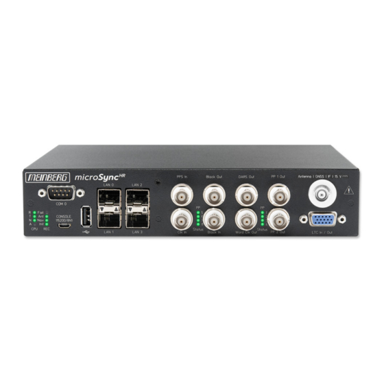
Page 18: Microsync Hr701/Dc - Connectors
5 microSync HR701/DC - Connectors 5.1 GPS Antenna Antenna input GPS180: Antenna circuit electrically isolated Dielectric strength: 1000 V Mixed frequency Reference clock to antenna (GPS-converter): 10 MHz IF frequency Antenna (GPS-converter) to reference clock: 35.4 MHz 1) these frequencies are transfered via the antenna cable... -
Page 19: Ltc/Gpio
5 microSync HR701/DC - Connectors 5.2 LTC/GPIO Signal: LTC-Reader (25 fps) Signal level: TTL; 2,5 V (MARK/SPACE) at 50 Ohm Pin Assignment: LTC_out + LTC symmetric HI Pot. Output LTC out - LTC symmetric Lo Pot. Output LTC_in + LTC symmetric HI-Poti. Input LTC in - LTC symmetric Lo Pot. -
Page 20: Status Leds - Vsg Signals
5.4 Status LEDs - VSG Signals Status indicator LED St: Status of the internal VSG LED In: Synchronization status LED A: Status of the blackburst output LED B: Status of the LTC output The status messages of the LEDs result as follows:. LED St: Blue During initialization... -
Page 21: Dars Input
5 microSync HR701/DC - Connectors 5.5 DARS Input Output signal: DARS Signal level: TTL; 2.5 V into 75 ohms Signal type: Base frequencies: 44.1 kHz and 48 kHz Connection type: BNC female connector Cable: Coaxial cable, shielded 5.6 Word Clock Output... -
Page 22: Blackburst Input
5.7 Blackburst Input Input Signal Black Burst (PAL) Input with VITC Reader Input with Prescaler mode (Frequency only) Signal level: 300 mV into 75 ohms (unbalanced) Time Code Formats: PAL SMPTE259M / ITU-R BT.470-6 SMPTE12M-1 / SMPTE ST309M Connection type: BNC female connector Cable: Coaxial cable, shielded... -
Page 23: Status Leds - Input Signals
5 microSync HR701/DC - Connectors 5.9 Status LEDs - input signals Status indicator LED B: Status of the blackburst input signal. LED L: Status of the LTC input signal LED C: Status of the Word Clock input signal LED P: Status of the PPS input signal The status messages of the LEDs are as follows:. -
Page 24: Pulse Per Second Input
5.10 Pulse Per Second Input Input signal PPS (pulse per second) Signal level: Pulse lenght: 5 s, active high Connection type: BNC, female Cable: Coaxial cable, shielded 5.11 Word Clock Input Input signal: Word Clock Input with programmable frequency range Signal level: Frequency range: 1 kHz - 10 MHz Cable:... -
Page 25: Lan Network Interfaces
5 microSync HR701/DC - Connectors 5.12 LAN Network Interfaces Gigabit Ethernet (GbE), 100/1000 MBit - SFP LAN 0, 1: Management / NTP 10/100/1000Mbit RJ45 or 1000FX LAN 2: Management 10/100/1000Mbit RJ45 or 1000FX NTP / PTP Master and Slave LAN 3:... -
Page 26: Rs-232 Comx Timestring
5.14 RS-232 COMx Timestring Data transfer: serial Baudrate/framing: 19200 / 8N1 (default) Time-string: Meinberg Standard (default) Assignment: Pin 2: RxD (receive) Pin 3: TxD (transmit) Pin 5: GND (ground) Connector: 9pin D-SUB male Cable: data cable (shielded) PC connector 1:1... -
Page 27: Status Indicators - Cpu And Receiver
5 microSync HR701/DC - Connectors 5.15 Status Indicators - CPU and Receiver CPU: —————————————————————————– R (Receiver) green: The reference clock (e.g. build-in GPS180) provides a valid time red: the reference clock does not provide a valid time T (Time Service) -
Page 28: Power Supply And Protective Earth Connection
, always follow the input voltage range specifications above. The desktop AC adapter, included in the scope of delivery, is approved by Meinberg for powering the microSync . Please use this power adapter for the power supply of the microSync system. - Page 29 5 microSync HR701/DC - Connectors Other specifications: Cable length (output): 1800 mm DC connector (right angle): (Ø 5.5/Ø 2.5) L10.5 mm AC input: IEC320/C14 Approval: IEC62368-1, UL62368-1, EN62368-1 For more detailed information about the desktop AC adapter, download the manufacturer’s datasheet: https://www.meinbergglobal.com/download/docs/other/Datasheet-TRH50A.pdf...
-
Page 30: Gnss Satellite Navigation
6 GNSS Satellite Navigation The satellite receiver clock GPS180 has been designed to provide extremely precise time to its user. The clock has been developed for applications where conventional radio controlled clocks can´t meet the growing require- ments in precision. High precision available 24 hours a day around the whole world is the main feature of the new system which receives its information from the satellites of the russian GLONASS (GLObal NAvigation Satellite System) and the american GPS (Global Positioning System). -
Page 31: Time Zone And Daylight Saving
6 GNSS Satellite Navigation 6.1 Time Zone and Daylight Saving GPS system time differs from the universal time scale (UTC) by the number of leap seconds which have been inserted into the UTC time scale since GPS was initiated in 1980. The current number of leap seconds is part of the navigation message supplied by the satellites, so the internal real time of the GPS180 is based on UTC time scale. -
Page 32: Installation Gps Antenna
7 Installation GPS Antenna WARNING! Antenna mounting without effective anti-fall protection Danger to life due to fall! - Pay attention to effective working safety when installing antennas! - Never work without an effective anti-fall equipment! WARNING! Working on the antenna system during thunderstorms Danger to life due to electrical shock! - Do not carry out any work on the antenna system or the antenna cable if there is a risk of a lightning strike. - Page 33 7 Installation GPS Antenna Antenna Mounting Mount the antenna at a distance of 50 cm from other Free view to the sky! antennas to a vertical pole up to 60 mm outer diameter or on a wall with the mounting kit included in the scope of delivery.
- Page 34 Earth cable to PE rail To ground the antenna cable, connect the surge Cable circa 1,5 mm Ø protection with a grounding cable to a equipotential attached to the surge protection bonding rail (see figure). After installation, connect the other end of the as short as possible antenna cable to the socket of the surge protection.
- Page 35 7 Installation GPS Antenna Antenna splitter option Several receivers can be connected to one antenna via the antenna splitter. Make sure, that the total length of a route going from the antenna via the splitter to the receiver, does not exceed the maximum cable length. The splitter may be installed at any position between the surge protector and the receiver.
-
Page 36: Starting Of Operation
The software is delivered on the USB stick included in the scope of delivery and does not need to be in- stalled or copied on the PC. The Meinberg Device Manager can be started directly from the USB data carrier. -
Page 37: Establishing A Network Connection
Authentication: The Username & Password option is only supported for modules with MeinbergOS. TCP Port: This TCP port is used to communicate with your Meinberg module. Please make sure it is open in your firewall configuration. Username (Optional): Enter the user name with which the Meinberg Device Manager should authenticate itself to your Meinberg system. -
Page 38: Connecting With The Network Configuration Wizard
Host Key Verification To enable a secure connection to the system via SSH, you must add the key used to your known hosts. This ensures that this device can be permanently identified as a trusted communication partner. To confirm, click on Yes. 8.1.1 Connecting with the Network Configuration Wizard The "Network Configuration Wizard"... -
Page 39: Technical Appendix
9 Technical Appendix 9 Technical Appendix 9.1 Technical Specifications GPS Receiver Receiver: 12 - channel C/A code receiver with external antenna/converter unit Antenna: antenna/converter unit with remote power supply refer to chapter "Technical specifications of antenna" Power Supply 15 V DC, continuous short circuit protection, automatic recovery for Antenna: isolation voltage 1000 VDC, provided via antenna cable Antenna Input:... - Page 40 Framing: 7E1, 7E2, 7N2, 7O1, 7O2, 8E1, 8N1, 8N2, 8O1 default setting: COM 0: 19200, 8N1 Meinberg Standard time string, per second Time Code Outputs: Unbalanced modulated sine wave signal: (MARK), 1 V (SPACE) into 50 ohm DCLS-signal: TTL into 50 ohm, active-high or -low...
-
Page 41: Configuration Options
9 Technical Appendix 9.2 Configuration Options Receiver Options RECEIVER TYPE SIGNAL TYPE VALUE CONNECTOR Meinberg GPS IF, 12-channel IF (Meinberg Antenna)) 15 V DC Meinberg GNS-UC GPS/Galileo IF IF (Meinberg Antenna)) 15 V DC GNSS (GPS, GLONASS, Galileo, BeiDou), 72-channel... -
Page 42: Technical Appendix - Gps Antenna + Accessories
10 Technical Appendix - GPS Antenna + Accessories Physical Dimensions: Date: 18th February 2021 microSync... - Page 43 10 Technical Appendix - GPS Antenna + Accessories Specifications: Power supply: 15 V, 100 mA (provided via antenna cable) Receive frequency: 1575.42 MHz Bandwidth: 9 MHz Frequencies: Mixed frequency 10 MHz IF frequency: 35.4 MHz Connector: N-Norm female connector Form factor: ABS plastic case for outdoor installation Protection class: IP66...
-
Page 44: Antenna Cable
10.1 Antenna Cable: Cable type Cable (mm/in) Attenuation at 100 MHz max. Cable lenght (m/ft) used for receiver type (db)/100m/328ft RG58/CU 5/0.2 300/984 GPS/GNS-UC/PZF RG213 10,3/0.41 700/2297 GPS/GNS-UC H155 5,4/0,21 70/230 GNM/GNS H2010 Ultraflex 7,3/0,29 150/492 GNM/GNS Further values can be found in the data sheet of the cable used. 10.2 Antenna Short-Circuit (Only for assembly groups with front display) In case of an antenna line short-circuit the following message appears in the display:... - Page 45 10 Technical Appendix - GPS Antenna + Accessories 10.3 Technical Specifications - MBG S-PRO surge protection Attachment plug with replaceable gas discharge tube for coaxial signal interfaces. Connection: N connector female/female. The MBG S-PRO set includes a surge voltage protector (Phoenix CN-UB-280DC-BB), a pre- assembled coax cable and a mounting bracket.
- Page 46 Max. discharge current (8/20) s maximum (Core-Shield) 20 kA Nominal pulse current (10/1000) s (Core-Shield) 100 A Impulse discharge current (10/350) s, peak value I 2,5 kA Output voltage limitation at 1 kV/ s (Core-Earth) spike 900 V at 1 kV/ s (Core-Earth) spike 900 V Response time tA (Core-Earth)
- Page 47 10 Technical Appendix - GPS Antenna + Accessories 10.3.1 MBG S-PRO - Physical Dimensions 15,8 10.3.2 Installation and Grounding microSync Date: 18th February 2021...
- Page 48 Any transportation expenses for return- ing this product (at its end of life) have to be incurred by the end user, whereas Meinberg will bear the costs for the waste disposal itself. Date: 18th February 2021...
- Page 49 12 Declaration of Conformity Declaration of Conformity Doc ID: microSync HR701/DC-2021-02-18 Hersteller Meinberg Funkuhren GmbH & Co. KG Manufacturer Lange Wand 9, D-31812 Bad Pyrmont erklärt in alleiniger Verantwortung, dass das Produkt, declares under its sole responsibility, that the product...
Need help?
Do you have a question about the microSync HR701/DC and is the answer not in the manual?
Questions and answers