Meinberg microSync HR100/DC Technical Reference
Hide thumbs
Also See for microSync HR100/DC:
- Technical reference (49 pages) ,
- Technical reference (52 pages)

Related Manuals for Meinberg microSync HR100/DC


Summary of Contents for Meinberg microSync HR100/DC
- Page 1 TECHNICAL REFERENCE microSync HR100/DC May 31, 2024 Meinberg Funkuhren GmbH & Co. KG...
-
Page 3: Table Of Contents
6 microSync Introduction 7 microSync HR100/DC Connectors GNSS Antenna .......... - Page 4 11.4.2 Meinberg GPS Time String ........
-
Page 5: Imprint
1 Imprint 1 Imprint Meinberg Funkuhren GmbH & Co. KG Lange Wand 9, 31812 Bad Pyrmont, Germany Phone: + 49 (0) 52 81 – 93 09 - 0 Fax: + 49 (0) 52 81 – 93 09 - 230 Website: https://www.meinbergglobal.com... -
Page 6: Copyright And Liability Exclusion
Meinberg reserves the right to make changes of any type to this document at any time as is necessary for the purpose of improving its products and services and ensuring compliance with applicable standards, laws &... -
Page 7: Presentation Conventions In This Manual
3 Presentation Conventions in this Manual 3 Presentation Conventions in this Manual 3.1 Conventions for the Presentation of Critical Safety Warnings Warnings are indicated with the following warning boxes, using the following signal words, colors, and symbols: Caution! This signal word indicates a hazard with a low risk level. Such a notice refers to a procedure or other action that may result in minor injury if not observed or if improperly performed. -
Page 8: Secondary Symbols Used In Safety Warnings
3.2 Secondary Symbols Used in Safety Warnings Some warning boxes may feature a secondary symbol that emphasizes the defining nature of a hazard or risk. The presence of an "electrical hazard" symbol is indicative of a risk of electric shock or lightning strike. -
Page 9: Generally Applicable Symbols
3 Presentation Conventions in this Manual 3.4 Generally Applicable Symbols The following symbols and pictograms are also used in a broader context in this manual and on the product. The presence of the "ESD" symbol is indicative of a risk of product damage caused by electrostatic discharge. -
Page 10: Important Safety Information
Depending on your specific device configuration and installed options, some safety information may not be applicable to your device. Meinberg accepts no responsibility for injury or death arising from a failure to observe the safety information, warnings, and safety-critical instructions provided in the product documentation. -
Page 11: Product Documentation
If any of the safety information in the product documentation is unclear for you, do not continue with the set-up or operation of the device! Safety standards and regulations change on a regular basis and Meinberg updates the corresponding safety information and warnings to reflect these changes. It is therefore recommended to regularly visit the Meinberg website at https://www.meinbergglobal.com or the Meinberg Customer Portal at... -
Page 12: Safety During Installation
Never drill holes into the device to mount it! If you are experiencing difficulties with rack installation, contact Meinberg’s Technical Support team for assistance! Inspect the device housing before installation. The device housing must be free of any damage when it is installed. -
Page 13: Grounding The Device
4 Important Safety Information 4.4 Grounding the Device In order to ensure that the device can be operated safely and to meet the requirements of IEC 62368- 1, the device must be correctly connected to the protective earth conductor via the protective earth terminal. -
Page 14: Electrical Safety
Always pull cable connectors out at both ends before performing work on connectors! Improperly connecting or disconnecting this Meinberg system may result in electric shock, possibly resulting in injury or death! When pulling out a connector, never pull on the cable itself! Pulling on the cable may cause the plug to become detached from the connector or cause damage to the connector itself. - Page 15 4 Important Safety Information 5-Pin MSTB Connector 3-Pin MSTB Connector = 100 - 200 V = 90 - 250 V Illustration: Lock screws on an MSTB plug connector; in this case on a LANTIME M320 Ensure that all plug connections are secure. In particular, when using plug connectors with lock screws, ensure that the lock screws are securely tightened.
-
Page 16: Special Information For Devices With Dc Power Supply
4.6 Safety when Handling SFP Modules The fiber-optic SFP modules recommended by Meinberg are equipped with a Class 1 laser. • Only use fiber-optic SFP modules that are compliant with the definition of a Class 1 laser in accordance with IEC standard 60825-1. -
Page 17: Safety When Maintaining And Cleaning The Device
If a power supply unit or module is no longer functional (for example due to a defect), it can be returned to Meinberg for repair. Some components of the device may become very hot during operation. Do not touch these surfaces! If maintenance work is to be performed on the device and the device housing is still hot, switch off... -
Page 18: Important Product Information
5 Important Product Information 5.1 CE Marking This product bears the CE mark as is required to introduce the product into the EU Single Market. The use of this mark is a declaration that the product is compliant with all requirements of the EU directives effective and applicable as at the time of manufacture of the product. -
Page 19: Maintenance And Modifications
5 Important Product Information 5.4 Maintenance and Modifications Important! Before performing any maintenance work on or authorized modification to your Meinberg system, we recommend making a backup of any stored configuration data (e.g., to a USB flash drive from the Web Interface). -
Page 20: Disposal
It can be returned to Meinberg for disposal. Any transportation expenses for returning this product (at end-of- life) must be covered by the end user, while Meinberg will bear the costs for the waste disposal itself. If you wish for Meinberg to handle disposal for you, please get in touch with us. Otherwise, please use the return and collection systems provided within your country to ensure that your device is disposed of in a compliant fashion to protect the environment and conserve valuable resources. -
Page 21: Microsync Introduction
• High performance (S)NTP server • Half rack solution for a space efficient design • Different Oscillator options for advanced holdover performance • Meinberg Device Manager for configuration and status monitoring • Three-year manufacturer‘s warranty • Unlimited technical support including firmware updates... -
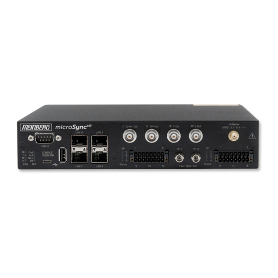
Page 22: Microsync Hr100/Dc Connectors
7 microSync HR100/DC Connectors 7.1 GNSS Antenna Antenna Type: Multi-GNSS L1 Antenna with integrated Lightning Protection Receiver Type: 72-Channel Receiver GPS/GLONASS/Galileo/BeiDou Signal Support: GPS: L1 C/A (1575.42 MHz) Galileo: E1-B/C (1575.42 MHz) BeiDou: B1I (1561.098 MHz) GLONASS: L1OF (1602 MHz + k*562.5 kHz) -
Page 23: Programmable Pulse Output
7 microSync HR100/DC Connectors Danger! Do not work on the antenna system during thunderstorms! Danger of death from electric shock! • Do not carry out any work on the antenna system or the antenna cable if there is a risk of lightning strike. -
Page 24: Time Code Am (Modulated) Output
7.3 Time Code AM (modulated) Output Signal outputs: Unbalanced sine wave-signal Signal level: / 1 V (MARK/SPACE) into 50 Ohm Carrier frequency: 1 kHz (IRIG-B) Connection type: BNC female Cable: shielded coax line (detailed information about time codes in chapter Description of Time Code Formats) 7.4 Frequency Synthesizer Output Output signal... -
Page 25: Rs-232 Comx Timestring
7 microSync HR100/DC Connectors 7.5 RS-232 COMx Timestring Data transfer: serial Baudrate/framing: 19200 / 8N1 (default) Time String: Meinberg Standard (default) (more information about time stringsin chapter Available Time Telegrams) Assignment: Pin 2: RxD (receive) Pin 3: TxD (transmit) Pin 5:... -
Page 26: Status Indicators - Cpu And Receiver
7.6 Status Indicators - CPU and Receiver CPU: —————————————————————————– R (Receiver) green: The reference clock (e.g. build-in GNS) provides a valid time red: the reference clock does not provide a valid time T (Time Service) green: NTP is synchronized to the reference clock, e.g. -
Page 27: Usb Interface
7 microSync HR100/DC Connectors 7.7 USB Interface Signal Signal Type Connector —————————————————————————– USB Terminal USB-to- Micro-USB Type B serial console USB Host USB connector USB Type A management CPU 7.8 LAN Network Interfaces Gigabit Ethernet (GbE), 100/1000 MBit - SFP... -
Page 28: Available Sfp Modules
Available SFP Modules Recommended and tested Transceivers from other Vendors Mode Vendor/Type Distance —————————————————————————————————————————————- MULTI MODE: AVAGO AFBR-5710PZ 550 m (1,805 ft) FINISAR FTLF8524P3BNL 500 m (1,640 ft) CISCO GLC-SX-MMD 220 m (722 ft) SINGLE MODE: AVAGO AFCT-5710PZ 10 km (32,808 ft) FINISAR FTLF1318P3BTL 10 km (32,808 ft) SMARTOPTICS SO-SFP-L120D-C63... -
Page 29: Dmc X2 Terminal Connector
7 microSync HR100/DC Connectors 7.9 DMC X2 Terminal Connector Note: The connector on the device side and the connection socket of the X2 terminal are provided with coding pins to avoid confusion with the X1 connection terminal. Pin 1 PP 5+... -
Page 30: Fiber Optic - Programmable Pulse Output
7.10 Fiber Optic - Programmable Pulse Output Output signal: Programmable signals, fiber optic Output Type: Fibre optic (FO) Wavelength: 850 nm (Multimode) Output Power: Typ. 15 W Connector Type: ST Connector Type of Fiber: GI 50/125 m or 62.5 m graded-index fiber Pulse outputs: Idle Timer... -
Page 31: Dmc X1 Terminal Connector / Dc Power Supply
7 microSync HR100/DC Connectors 7.11 DMC X1 Terminal Connector / DC Power Supply Note: The connector on the device side and the connection socket of the X1 terminal are provided with coding pins to avoid confusion with the X2 connection terminal. - Page 32 Scheme Terminal assignment Programmable Pulses Standard (Opto Coupler) Four programmable outputs (PP 1 - PP 4) DC-insulated by optocouplers PP 1 + Channel 1 PP 1 = 55 V CEmax PP 2 + = 50 mA Channel 2 Cmax = 150 mW PP 2 PP 3 + Channel 3...
-
Page 33: Information On Satellite Reception
Your system is fitted with the GNS, a 72-channel satellite receiver clock which serves as a high-accuracy time reference and high-precision frequency reference for your Meinberg system and is designed to receive signals from the United States GPS (Global Positioning System), Russian GLONASS (GLObal NAvigation Satellite System), the European Galileo system, and the Chinese BeiDou system. -
Page 34: Satellite Systems
Satellite Systems GPS was installed by the United States Department of Defense (US DoD) and operates at two performance levels: the Standard Positioning Service, or SPS, and the Precise Positioning Service, or PPS. The structure of the messages transmitted by the SPS has been openly published and reception is provided for public use. The timing and navigation data of the more precise PPS is encrypted and is thus only accessible to certain (usually military) users. -
Page 35: Installation Of A Gnss Antenna
1. Mounted on a pole 2. Mounted on a wall To avoid difficulties with synchronization of your Meinberg time server, select a location that allows for an unobstructed view of the sky (fig. 1) so as to ensure that enough satellites can be found. - Page 36 • A clear view between 55th north and 55th south parallels (satellite orbits). Information: Problems may arise with the synchronization of your Meinberg time server if these conditions are not met, as four satellites must be located to calculate the exact position.
-
Page 37: Mounting The Antenna
9 Installation of a GNSS Antenna 9.2 Mounting the Antenna Please read the following safety information carefully before installing the antenna and ensure that it is ob- served during the installation. Danger! Do not mount the antenna without an effective fall arrester! Danger of death from falling! •... -
Page 38: Antenna Cable
Meinberg provides suitable cable types with its antennas and these are ordered together with the antenna to match the length you need from your antenna to your Meinberg reference clock. The route to be covered for your antenna installation should be determined and the appropriate cable type selected accordingly before confirming your order. - Page 39 9 Installation of a GNSS Antenna Laying the Antenna Cable When laying the antenna cable, ensure that the specified maximum cable length is not exceeded. This length will depend on the selected cable type and its attenuation factor. If the specified maximum length is exceeded, correct transmission of the synchronization data and thus proper synchronization of the reference clock can no longer be guaranteed.
- Page 40 Compensating for Signal Propagation Time GNS Clocks The propagation of the signal from the antenna to the receiver (reference clock) can incur a certain delay. This delay can be compensated for in the meinbergOS Web Interface. To do this, log into the Web Interface of your microSync system and proceed as follows: Open the menu "Configuration"...
-
Page 41: Surge Protection And Grounding
DIN EN 60728-11) for more information. In order to preserve the safety of the building and to protect your Meinberg system, Meinberg recomends the use of the MBG-S-PRO surge protector, which is addressed in more detail later in this chapter. -
Page 42: Electrical Bonding
Electrical Bonding Electrical bonding is the connection of all metallic, electrically conductive elements of the antenna instal- lation in order to limit the risk of dangerous voltages for people and connected devices. To this end, the following elements should be connected and integrated into a bonding system: •... - Page 43 9 Installation of a GNSS Antenna The drawings below illustrate how a Multi-GNSS-Antenne can be installed in accordance with the above con- ditions on a pole (e.g. antenna pole) or building roof. Antenna Installation without Insulated Lightning Rod System α Fig.
- Page 44 Antenna Installation with Insulated Lightning Rod System α Fig. 6: Roof Installation Multi GNSS Antenna Lightning Rod Lightning Rod Conductor Antenna Cable Bonding Conductor Bonding Bar Foundation Electrode Safety Zone Date: May 31, 2024 microSync...
-
Page 45: Installation Conditions
9 Installation of a GNSS Antenna MBG S-PRO Surge Protector Information: The surge protector and suitable coaxial cable are not included as standard with a Multi-GNSS- Antenne, but can be ordered as an optional accessory. Construction The MBG-S-PRO is a surge protector (Phoenix CN-UB-280DC-BB) for coaxial connections. It is patched directly into the antenna line and consists of a replaceable gas discharge tube that redirects the energy from the cable shielding to the ground potential when ignited. -
Page 46: Installation And Connection
Meinberg system to prevent destructive potential differences. Connect the coaxial cable from the antenna to one of the surge protector connectors, then connect the other surge protector connector to the coaxial cable leading to the Meinberg reference clock. Caution! -
Page 47: Starting Of Operation
• Configuration via a serial connection, see Chapter 10.1.1. • Configuration via the Web Interface, see Chapter 10.1.2. • Configuration via Meinberg Device Manager, see Chapter 10.1.3. 10.1.1 Network Configuration via Serial Connection The initial network configuration of the microSync can also be performed via a serial USB connection. You can connect the USB port on the PC with the micro-USB port of the microSync using a standard USB cable (Micro-USB Type B to USB-A). - Page 48 Web Interface or Meinberg Device Manager. Information: If the microSync’s network configuration has already been previously performed using the Web Interface or Meinberg Device Manager, you will not be able to do this using mbgOSWizard.sh. Date: May 31, 2024 microSync...
-
Page 49: Network Configuration Via Web Interface
10 Starting of Operation 10.1.2 Network Configuration via Web Interface The network configuration for the microSync can be performed via the Web Interface. In its factory-shipped state, the microSync has the following network configuration: Network Port LAN 0 192.168.19.79 IPv4 Address: 255.255.255.0 Subnet Mask: Gateway:... - Page 50 As soon as the Dashboard appears, click on the "Configuration" section in the Header Bar, then select the "Network" tile. Be sure in particular to correctly configure the network settings for the intended management interface ("Interfaces" tab) to ensure that it is accessible within the subnet. Once you have performed the configuration, click on "Save"...
-
Page 51: Network Configuration Via Meinberg Device Manager
Supported Linux distributions include Ubuntu, Mint Linux, Debian, SUSE Linux, CentOS, and others. The software does not need to be installed or copied on the PC. The Meinberg Device Manager can be started directly from an USB storage device. The computer must be connected to the network in which the microSync system is connected. - Page 52 DHCP: Disabled The PC on which Meinberg Device Manager is used must be able to establish a network connection with the above address in the appropriate subnet. If the PC’s network configuration or the network’s topology or addressing prevent a connection from being established with the microSync, the network configuration of the PC will need to be (temporarily) changed and a different physical connection may need to be established (e.g.
- Page 53 10 Starting of Operation If the inserted microSync cannot be found via the automatic search, the Add Device button can be used to set up the connection manually. Manual Setup Select the connection type microSyncHR, microSyncRX (Network). Then enter the IPv4 address of the microSync (192.168.19.79).
-
Page 54: Initial Start Of Operation
(Figure 10.1). The default settings are: admin Username: Password: timeserver Further information about the meinbergOS web interface in the chapter "The meinbergOS Web Interface" to be found in the microSync installation manual: https://www.meinberg.de/download/docs/manuals/english/microsync.pdf Date: May 31, 2024 microSync... -
Page 55: Start Of Operation With Meinberg Device Manager Software
10.2.2 Start of Operation with Meinberg Device Manager Software First install the Meinberg Device Manager software. After the setup, start the program. If you do not wish to install the software on your local PC, you can also download the "Portable Version" of Meinberg Device Manager and launch it directly from a portable USB storage medium. - Page 56 User and Password fields are already filled out. Silent Login You have the option that the Meinberg Device Man- ager does not ask for a user name and password every time you log in. Custom Alias Assign a custom alias for better identification of indi-...
-
Page 57: Technical Appendix
11 Technical Appendix 11 Technical Appendix 11.1 Technical Specifications microSync Chassis Chassis Type: 9,5" (Half-Rack), 1U Chassis Material: Sheet Steel ——————————————————————————- Temperature Range Operation: 0 C to 50 C (32 F to 122 F) Storage: –20 C to 70 C (–4 F to 158 F) ——————————————————————————- Supported Relative Humidity Operation:... - Page 58 Physical Dimensions: 482.6 mm [ 19 inch ] 465.1 mm [ 18.31 inch ] 43.7 mm 31.8 mm [ 1.72 inch ] [ 1.25 inch ] 223 mm [ 19 inch ] 251 mm [ 9.88 inch ] 236 mm [ 9.29 inch ] Date: May 31, 2024 microSync...
-
Page 59: Description Of Time Code Formats
Each IRIG format carries a designation comprising a letter followed by three numerical digits. The letter and each of the digits represents a characteristic property of the corresponding IRIG code. Depending on your Meinberg product, more or less time code formats are supported. A002:... - Page 60 Abbreviations: BCD = Binary-Coded Decimal, SBS = Straight Binary Seconds In addition to the original IRIG standards, there are also other specifications issued by other bodies that define specific extensions. AFNOR: Code according to NF S87-500, 100 pps, AM sine-wave signal, 1 kHz carrier frequency, BCD time of year, complete date, SBS time of day, signal level specified by standard.
-
Page 61: Description Of Programmable Pulse Outputs
AND the internal timebase is synchro- nized to the GPS timing. DCLS Time Code DC Level Shift Time Code. The selection of the time code is done by the Meinberg Device Manager menu "Outputs Settings". microSync... - Page 62 1 MHz Frequency, 5 MHz Frequency, 10 MHz Frequency These modes are used to output a fixed frequency, using a PPS signal as an absolute phase reference (i.e., the falling edge of the selected frequency signal is synchronized with the rising edge of the PPS signal). When the system is set to output a 1, 5, or 10 MHz frequency, these frequency signals will only be out- put when the oscillator is phase-locked to its reference, regardless of the output condition setting ("if sync"...
-
Page 63: Available Time Telegrams
11.4 Available Time Telegrams 11.4.1 Meinberg Standard Time String The Meinberg Standard Time String is a sequence of 32 ASCII characters starting with the <STX> (Start-of- Text) character and ending with the <ETX> (End-of-Text) character. The format is as follows: <STX>D:dd.mm.yy;T:w;U:hh.mm.ss;uvxy<ETX>... -
Page 64: Meinberg Gps Time String
<ETX> (End-of-Text) character. Unlike the Meinberg Standard Time String, the Meinberg GPS Time String does not carry any local time zone or UTC data; it simply carries the direct GPS time without any conversion into UTC. The format is as follows: <STX>D:dd.mm.yy;T:w;U:hh.mm.ss;uvGy;lll<ETX>... -
Page 65: Meinberg Capture String
11 Technical Appendix 11.4.3 Meinberg Capture String The Meinberg Capture String is a sequence of 31 ASCII characters terminated by a <CR><LF> (Carriage Return/Line Feed) sequence. The format is as follows: CHx<SP>dd.mm.yy_hh:mm:ss.fffffff<CR><LF> The letters printed in italics are replaced by ASCII-formatted numbers, whereas the other characters are directly part of the time string. -
Page 66: Format Of The Spa Time String
11.4.4 Format of the SPA Time String The ABB SPA Time String is a sequence of 32 ASCII characters starting with the characters ">900WD" and ending with the <CR> (Carriage Return) character. The format is: >900WD:jj-mm-tt_hh.mm;ss.fff:cc<CR> The letters printed in italics are replaced by ASCII numbers whereas the other characters are part of the time string. -
Page 67: Sat Time String
11 Technical Appendix 11.4.5 SAT Time String The SAT Time String is a sequence of 29 ASCII characters starting with the <STX> (start-of-text) character and ending with the <ETX> (end-of-text) character. The format is as follows: <STX>dd.mm.yy/w/hh:mm:ssxxxxuv<ETX> The letters printed in italics are replaced by ASCII-formatted numbers, whereas the other characters are directly part of the time string. -
Page 68: Uni Erlangen String (Ntp)
11.4.6 Uni Erlangen String (NTP) The Uni Erlangen String (NTP) of a GPS clock is a sequence of 66 ASCII characters starting with the <STX> (start-of-text) character and ending with the <ETX> (end-of-text) character. The format is as follows: <STX>dd.mm.yy; w; hh:mm:ss; voo:oo; acdfg i;bbb.bbbbn lll.lllle hhhhm<ETX> The letters printed in italics are replaced by ASCII-formatted numbers, whereas the other characters are directly part of the time string. - Page 69 11 Technical Appendix Latitudinal hemisphere, with the following characters possible: ‘N’ North of Equator ‘S’ South of Equator lll.llll Geographical longitude of receiver position in degrees Leading characters padded by Space characters (20h) Longitudinal hemisphere, with the following characters possible: ‘E’...
-
Page 70: Nmea 0183 String (Rmc)
West of Greenwich Meridian Speed over the ground in knots and track angle in degrees. 0.0,0.0 With a Meinberg GPS clock, these values are always 0.0, With GNS clocks, the values are calculated by the receiver for mobile applications The date:... -
Page 71: Nmea 0183 String (Gga)
11 Technical Appendix 11.4.8 NMEA 0183 String (GGA) The NMEA 0193 GGA String is a sequence of characters starting with the string "$GPGGA" and ending with the characters <CR> (Carriage Return) and <LF> (Line Feed). The format is as follows: $GPGGA,hhmmss.ff,bbbb.bbbbb,n,lllll.ll,e,A,vv,hhh.h,aaa.a,M, ggg.g,M,,0 * cs<CR><LF>... -
Page 72: Nmea 0183 String (Zda)
11.4.9 NMEA 0183 String (ZDA) The NMEA 0183 ZDA String is a sequence of 38 ASCII characters starting with the string "$GPZDA" and ending with the characters <CR> (Carriage Return) and <LF> (Line Feed). The format is: $GPZDA,hhmmss.ss,dd,mm,yyyy,HH,II * cs<CR><LF> ZDA - Time and Date: UTC, day, month, year, and local time zone. -
Page 73: Computime Time String
11 Technical Appendix 11.4.10 Computime Time String The Computime time string is a sequence of 24 ASCII characters, starting with the character T and terminated with the character <LF> (Line Feed, ASCII code 0Ah). The format is as follows: T:yy:mm:dd:ww:hh:mm:ss<CR><LF> The letters printed in italics are replaced by ASCII numbers whereas the other characters are unalterable parts of the time string. -
Page 74: Racal Standard Time String
11.4.11 RACAL Standard Time String The RACAL Standard Time String is a sequence of 16 ASCII characters started by a X character and terminated by the <CR> (Carriage Return, ASCII code 0Dh) character. The format is as follows: XGUyymmddhhmmss<CR> The letters printed in italics are replaced by ASCII-formatted numbers, whereas the other characters are directly part of the time string. -
Page 75: Sysplex-1 Time String
11 Technical Appendix 11.4.12 SYSPLEX-1 Time String The SYSPLEX-1 time string is a sequence of 16 ASCII characters starting with the <SOH> (Start-of-Header) ASCII control character and terminated with the <LF> (Line Feed, ASCII code 0Ah) character. Important! To ensure that the time string can be correctly output and displayed through any given terminal program, a singular "C"... -
Page 76: Ion Time String
11.4.13 ION Time String The ION time string is a sequence of 16 ASCII characters starting with the <SOH> (Start of Header, ASCII code 01h) ASCII control character and ending with the <LF> (Line Feed, ASCII code 0Ah) character. The format is as follows: <SOH>ddd:hh:mm:ssq<CR><LF>... -
Page 77: Ion Blanked Time String
11 Technical Appendix 11.4.14 ION Blanked Time String The ION Blanked time string is a sequence of 16 ASCII characters starting with the <SOH> (Start of Header, ASCII code 01h) ASCII control character and ending with the <LF> (Line Feed, ASCII code 0Ah) character. The format is as follows: <SOH>ddd:hh:mm:ssq<CR><LF>... -
Page 78: Irig-J Timecode
11.4.15 IRIG-J Timecode The IRIG-J timecode consists of a string of ASCII characters sent in "701" format, i.e.,: • 1 Start Bit • 7 Data Bits • 1 Parity Bit (odd) • 1 Stop Bit The on-time marker of the string is the leading edge of the start bit. The timecode consists of 15 characters, sent once per second at a baud rate of 300 or greater. -
Page 79: 6021 Time String
11 Technical Appendix 11.4.16 6021 Time String The 6021 time string is a sequence of 18 ASCII characters starting with the <STX> (Start-of-Text, ASCII code 02h) ASCII control character and terminated with the sequence <LF> (Line Feed, ASCII code 0Ah), <CR> (Car- riage Return, ASCII code 0Dh), <ETX>... - Page 80 Line Feed (ASCII code 0Ah) <LF> Carriage Return (ASCII code 0Dh) <CR> End-of-Text (ASCII code 03h) <ETX> * With ASCII nibbles, the actual ASCII character itself (0–9, A–F, ASCII codes 0x30h–0x39h and 0x41h–0x46h) represents the hexadecimal equivalent of a 4-bit binary sequence.
-
Page 81: Freelance Time String
11 Technical Appendix 11.4.17 Freelance Time String The Freelance time string is a sequence of 18 ASCII characters starting with the <STX> (Start-of-Text, ASCII code 02h) ASCII control character and terminated with the sequence <CR> (Carriage Return, ASCII code 0Dh), <LF>... - Page 82 Carriage Return (ASCII code 0Dh) <CR> Line Feed (ASCII code 0Ah) <LF> End-of-Text (ASCII code 03h) <ETX> * With ASCII nibbles, the actual ASCII character itself (0–9, A–F, ASCII codes 0x30h–0x39h and 0x41h–0x46h) represents the hexadecimal equivalent of a 4-bit binary sequence.
-
Page 83: Configuration Options
11 Technical Appendix 11.5 Configuration Options Receiver Options RECEIVER TYPE SIGNAL TYPE VALUE CONNECTOR Meinberg GPS IF, 12-channel IF (Meinberg Antenna)) 15 V DC Meinberg GNS-UC GPS/Galileo IF IF (Meinberg Antenna)) 15 V DC GNSS (GPS, GLONASS, Galileo, BeiDou), 72-Channel... -
Page 84: Technical Appendix: Gnss Antennas + Accessories
12 Technical Appendix: GNSS Antennas + Accessories 12.1 Technical Specifications: 40 dB Multi GNSS Antenna GPS L1 / GLONASS L1 / Galileo E1 / BeiDou B1 Frequency Band GPS, GLONASS, Galileo, and BeiDou satellites do not hold a geostationary orbit, but circle the Earth once roughly every 12 hours. -
Page 85: Technical Specifications: Mbg-S-Pro Surge Protector
12 Technical Appendix: GNSS Antennas + Accessories 12.2 Technical Specifications: MBG-S-PRO Surge Protector The MBG-S-PRO is a surge protector (Phoenix CN-UB-280DC-BB) for coaxial connections. It is patched directly into the antenna line and consists of a replaceable gas discharge tube that redirects the energy from the cable shielding to the ground potential when ignited. -
Page 86: Technical Specifications: Rv-76G Gps/Glonass Antenna For Mobile Applications
12.3 Technical Specifications: RV-76G GPS/GLONASS Antenna for Mobile Applications Installation of the Antenna Further Information on the Product Detailed specifications are provided in the manufacturer’s data sheet. Source: RV-76G_Catalog_V1.0_20130502 Data Sheet (Sanav) https://www.meinbergglobal.com/download/docs/other/rv-76g_en.pdf Download: Date: May 31, 2024 microSync... -
Page 87: Rohs Conformity
13 RoHS Conformity 13 RoHS Conformity Conformity with EU Directive 2011/65/EU (RoHS) We hereby declare that this product is compliant with the European Union Directive 2011/65/EU and its delegated directive 2015/863/EU "Restrictions of Haz- ardous Substances in Electrical and Electronic Equip- ment"... -
Page 88: Declaration Of Conformity For Operation In The European Union
14 Declaration of Conformity for Operation in the European Union EU-Konformitätserklärung Doc ID: microSync HR100/DC-May 31, 2024 Hersteller Meinberg Funkuhren GmbH & Co. KG Manufacturer Lange Wand 9, D-31812 Bad Pyrmont erklärt in alleiniger Verantwortung, dass das Produkt, declares under its sole responsibility, that the product... -
Page 89: Declaration Of Conformity For Operation In The United Kingdom
15 Declaration of Conformity for Operation in the United Kingdom 15 Declaration of Conformity for Operation in the United Kingdom UK Declaration of Conformity Doc ID: microSync HR100/DC-May 31, 2024 Manufacturer Meinberg Funkuhren GmbH & Co. KG Lange Wand 9...
Need help?
Do you have a question about the microSync HR100/DC and is the answer not in the manual?
Questions and answers