Meinberg MicroSync Technical Reference
Hide thumbs
Also See for MicroSync:
- Technical reference (50 pages) ,
- Technical reference (41 pages) ,
- Technical reference (44 pages)

Related Manuals for Meinberg MicroSync


Summary of Contents for Meinberg MicroSync
- Page 1 TECHNICAL REFERENCE microSync RX301/AD10DC20 17th June 2020 Meinberg Funkuhren GmbH & Co. KG...
-
Page 3: Table Of Contents
1 Imprint 2 microSync Introduction 3 Technical Specifications microSync Chassis 4 Important Safety Information Important Safety Instructions and Protective Measures ...... -
Page 4: Imprint
1 Imprint 1 Imprint Meinberg Funkuhren GmbH & Co. KG Lange Wand 9, 31812 Bad Pyrmont / Germany Phone: + 49 (0) 52 81 / 93 09 - 0 Fax: + 49 (0) 52 81 / 93 09 - 230 Internet: https://www.meinbergglobal.com... -
Page 5: Microsync Introduction
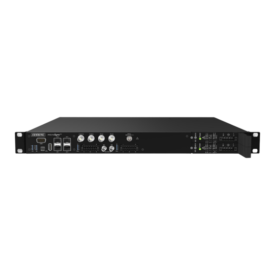
2 microSync Introduction microSync is a multipurpose synchronization solution with compact design and high performance. The mi- croSync system provides multiple output signals and allows synchronization of both NTP clients and PTP slaves. The device has four 100/1000 MBit network interfaces and can provide both, optical and electrical network connections by using SFP modules. -
Page 6: Technical Specifications Microsync Chassis
3 Technical Specifications microSync Chassis 3 Technical Specifications microSync Chassis Protection Rating: IP30 Ambient Temperature: -20 ... 55 C Storage Temperature: -30 ... 70 Humidity: 5% to 95% (non-condensing) @ 40 C Operating Altitude: up to 4,000 m (13,123 ft) above sea level... -
Page 7: Important Safety Information
Meinberg Funkuhren shall not be responsible for any damage arising due to non-observance of these regulations. -
Page 8: Used Symbols
Dieses Produkt fällt unter die B2B Kategorie. Zur Entsorgung muss es an den Hersteller übergeben werden. This product is handled as a B2B category product. In order to secure a WEEE compliant waste disposal it has to be returned to the manufacturer. microSync Date: 17th June 2020... - Page 9 This manual is intended exclusively for electricians or persons trained by an electrician who are familiar with the applicable national standards and safety rules. Installation, commissioning and operation of this device may only be carried out by qualified personnel. Date: 17th June 2020 microSync...
-
Page 10: Security During Installation
For safety reasons, the device with the highest mass should be installed in the lowest position of the rack. Other devices must be placed from the bottom to the top. The device must be protected against mechanical stress such as vibration or shock. microSync Date: 17th June 2020... - Page 11 fluids or foreign objects enter), the current flow can be interrupted. Questions about the house installation, need to be clarified with your house administration. The power supply should be connected with a short, low-inductance line. Date: 17th June 2020 microSync...
- Page 12 Date: 17th June 2020...
-
Page 13: Protective Conductor- / Ground-Terminal
Devices that are connected via one or more uninterruptible power supplies (UPS) remain operational even when the UPS power cord is disconnected. Therefore, you must put the UPS out of operation according to the documentation of the corresponding user documentation. Date: 17th June 2020 microSync... -
Page 14: Safety During Maintenance
Risk of explosion if the battery is not replaced correctly. Replace only with the same or equivalent type recommended by the manufacturer. When disposing used batteries, observe the local regulations for the disposal of hazardous waste. microSync Date: 17th June 2020... -
Page 15: Cleaning And Care
ESD protective covers, which are extremely wrinkled or even have holes, no longer protect against electrostatic discharge. ESD protective covers must not be low-resistance and metallically conductive if a lithium battery is installed on the assembly. Date: 17th June 2020 microSync... -
Page 16: Return Of Electrical And Electronic Equipment
Return and Collection Systems For returning your old equipment, please use the country-specific return and collection systems available to you or contact Meinberg. The withdrawal may be refused in the case of waste equipment which presents a risk to human health or safety due to contamination during use. -
Page 17: Microsync Rx301/Ad10Dc20 Connectors
The LED of the new power supply should now light up. Furthermore, the status Power Supply "green" should be displayed in the Status System menu of the Meinberg Device Manager. The status LED of the new power supply should now light up. The "OK" status must be displayed in the system’s web interface. - Page 18 5 microSync RX301/AD10DC20 Connectors Checking Power Status The status of the power supplies can be observed in the program Meinberg Device Manager under "Status System Status". AD10 - AC/DC Power Supply Connector Type: 5-pol. DFK AD10 AD10 Pin Assignment: 1: N/-...
- Page 19 = 2.10 A Input Parameter ———————————————————————————— Nominal Voltage Range: 24-48 V Maximum Voltage Range: 20-60 V Nominal Current: 2.10 A Output Parameter ———————————————————————————— Maximum Power: 50 W Max. Heat Emission: 180.00 kJ/h (170.61 BTU/h) therm Date: 17th June 2020 microSync...
-
Page 20: Gps Antenna
5 microSync RX301/AD10DC20 Connectors 5.2 GPS Antenna Cable: shielded coax Cablelength: max. 300m to RG58, Antenna max. 700m to RG213 GNSS | IF | 15 V Connector: BNC female or N-type female Input GPS: Antenna circuit 1000 V DC insulated... -
Page 21: 10 Mhz Frequency Output
< -65 dBc 10 MHz sine Out Phase noise: < -115 dBc/Hz at 10 Hz < -130 dBc/Hz at 100 Hz < -140 dBc/Hz at 1 KHz Connection type: BNC, female Cable: shielded coax line Date: 17th June 2020 microSync... -
Page 22: Pulse Per Second Input
5 microSync RX301/AD10DC20 Connectors 5.5 Pulse Per Second Input Input signal PPS (pulse per second) Signal level: Pulse lenght: 5 s, active high Connection type: BNC, female PPS In Cable: shielded coax line 5.6 10 MHz Input Input signal 10 MHz sinusoidal signal or TTL Level: 1.5 V... -
Page 23: Status Indicators
Init blue: initialisation phase green: "warmed up" - oscillator is adjusted —————————————————————————– Date: 17th June 2020 microSync... -
Page 24: Usb Interface
5 microSync RX301/AD10DC20 Connectors 5.9 USB Interface Signal Signal Type Connector —————————————————————————– USB Terminal USB-to- Micro-USB Type B serial console USB Host USB connecor USB Type A management CPU 5.10 LAN Network Interfaces Gigabit Ethernet (GbE), 100/1000 MBit - SFP... -
Page 25: Dmc X2 Terminal Connector
CEmax Channel 5 = 50 mA PP 5 + Cmax = 150 mW Response time Turn on Time: typ. 5 s, max. 9 s Pulse generator Turn off Time: typ. 10 s, max. 70 s Date: 17th June 2020 microSync... -
Page 26: Fiber Optic - Programmable Pulse Output
5 microSync RX301/AD10DC20 Connectors 5.12 Fiber Optic - Programmable pulse Output Output signal: Programmable pulses, fiber optic Wave lenght: 850nm (multi mode) PP 7 PP 8 Connection type: ST-connector GI 50/125 m or 62,5 m gradient fibre Fiber Optic Out... -
Page 27: Dmc X1 Terminal Connector
Pin 14 PP 4+ programmable pulse Zum X1-Geräteanschluss Pin 15 not used Pin 16 REL-NC Error-Relay (normally closed) Status-LEDs: PP 1 . . . PP 4 Status of the programmable Kabeleingang Pulses Out Date: 17th June 2020 microSync... - Page 28 5 microSync RX301/AD10DC20 Connectors Scheme Terminal assignment Programmable Pulses Standard (Opto Coupler) Four programmable outputs (PP 1 - PP 4) DC-insulated by optocouplers PP 1 + Channel 1 PP 1 = 55 V CEmax PP 2 + = 50 mA...
-
Page 29: Gnss Satellite Navigation
Galileo services will be free and open to everyone. The complete 30-satellite Galileo system (24 operational and 6 active spares) is expected by 2020. At an altitude of 23,222 km above the Earth’s surface, the satellites require about 14 hours for one orbit. Date: 17th June 2020 microSync... -
Page 30: Time Zone And Daylight Saving
GPS180 is based on UTC time scale. Conversion to local time and annual daylight saving time can be done by the receiver’s microprocessor if the corresponding parameters are set up by the user. microSync Date: 17th June 2020... -
Page 31: Mounting The Gps Antenna
- Do not carry out any work on the antenna system or the antenna cable if there is a risk of a lightning strike. - Do not carry out any work on the antenna system if the safety distance to free lines and sequential circuits is exceeded. Date: 17th June 2020 microSync... -
Page 32: Antenna Cable
(db)/100m/328ft RG58/CU 5/0.2 300/984 GPS/GNS-UC/PZF RG213 10,3/0.41 700/2297 GPS/GNS-UC H155 5,4/0,21 70/230 GNM/GNS H2010 Ultraflex 7,3/0,29 150/492 GNM/GNS Further values can be found in the data sheet of the cable used. microSync Date: 17th June 2020... -
Page 33: Antenna Assembly With Surge Voltage Protection
GPS Antenna N-Norm female N-Norm male Cable Slot N-Norm male N-Norm female as short as possible N-Norm female Meinberg GPS N-Norm male N-Norm male female Ground lead to PE rail or BNC male female (Protective Earth) Cable ca. 1,5 mm Ø... -
Page 34: Starting Of Operation
The software is delivered on the USB stick included in the scope of delivery and does not need to be in- stalled or copied on the PC. The Meinberg Device Manager can be started directly from the USB data carrier. -
Page 35: Establishing A Network Connection
Meinberg Device Manager should authenticate itself to your Meinberg system. Silent Login: you have the possibility that the Meinberg Device Manager will not ask for your username and password every time you log in. Changing your Network Password To change the password for the currently logged in user, click this icon. -
Page 36: Connecting With The Network Configuration Wizard
To confirm, click on Yes. 8.1.1 Connecting with the Network Configuration Wizard The "Network Configuration Wizard" allows you to connect to your microSync system. Start the Network Configuration Wizard You will find the wizard in the Section 4 of the start screen on the bottom right. This opens by clicking on the button. -
Page 37: Technical Appendix
< 0.0047 Hz Synthesizer Outputs: F_SYNTH: TTL level F_SYNTH_OD: open drain drain voltage: < 100 V sink current to GND: < 100 mA dissipation power at 25 C: < 360 mW F_SYNTH_SIN: sine-wave Date: 17th June 2020 microSync... - Page 38 Framing: 7E1, 7E2, 7N2, 7O1, 7O2, 8E1, 8N1, 8N2, 8O1 default setting: COM0: 19200, 8N1 Meinberg Standard time string, per second Time Code Outputs: Unbalanced modulated sine wave signal: (MARK), 1 V (SPACE) into 50 ohm DCLS-signal: TTL into 50 ohm, active-high or -low...
-
Page 39: Configuration Options
9.2 Configuration Options Receiver Options RECEIVER TYPE SIGNAL TYPE VALUE CONNECTOR Meinberg GPS IF, 12-channel IF (Meinberg Antenna)) 15 V DC BNC Meinberg GNS-UC GPS/Galileo IF IF (Meinberg Antenna)) 15 V DC GNSS (GPS, GLONASS, Galileo, BeiDou), 72-channel L1/E1/B1 band... -
Page 40: Rohs And Weee
Any transportation expenses for return- ing this product (at its end of life) have to be incurred by the end user, whereas Meinberg will bear the costs for the waste disposal itself. microSync... -
Page 41: Declaration Of Conformity
11 Declaration of Conformity Declaration of Conformity Doc ID: microSync RX301/AD10DC20-2020-06-17 Hersteller Meinberg Funkuhren GmbH & Co. KG Manufacturer Lange Wand 9, D-31812 Bad Pyrmont erklärt in alleiniger Verantwortung, dass das Produkt, declares under its sole responsibility, that the product...
Need help?
Do you have a question about the MicroSync and is the answer not in the manual?
Questions and answers