Lantronix SGX 5150 User Manual
Iot device gateway
Hide thumbs
Also See for SGX 5150:
- Quick start manuals (2 pages) ,
- Command reference manual (372 pages) ,
- Manual (27 pages)

Related Manuals for Lantronix SGX 5150


Summary of Contents for Lantronix SGX 5150
-
Page 1: User Guide
SGX 5150 IoT Device Gateway User Guide Part Number 900-776-R Revision D January 2018... -
Page 2: Intellectual Property
Technical Support Online: www.lantronix.com/support Sales Offices For a current list of our domestic and international sales offices, go to the Lantronix web site at www.lantronix.com/about/contact. Open Source Software Some applications are Open Source software licensed under the Berkeley Software Distribution... -
Page 3: Disclaimer
Lantronix shall have no liability whatsoever to any user for any damages, losses and causes of action (whether in contract or in tort or otherwise) in connection with the user’s access or usage of any of the information or content contained herein. -
Page 4: Table Of Contents
Summary of Chapters ______________________________________________________ 15 Additional Documentation ___________________________________________________ 15 2: Introduction Key Features _____________________________________________________________ 17 Applications ______________________________________________________________ 18 SGX 5150 User Cases _____________________________________________________ 19 Protocol Support __________________________________________________________ 19 Troubleshooting Capabilities _________________________________________________ 20 Configuration Methods _____________________________________________________ 20 Addresses and Port Numbers ________________________________________________ 20... - Page 5 Optional SGX 5150 Bracket _________________________________________________ 30 Wireless Quick Connect ____________________________________________________ 31 4: Using DeviceInstaller Installing DeviceInstaller ____________________________________________________ 32 Accessing the SGX 5150 Using DeviceInstaller __________________________________ 32 Next Step ____________________________________________________________ 34 5: Configuration Using Web Manager Accessing Web Manager ___________________________________________________ 35...
-
Page 6: Tm 5150 Iot Device Gateway User Guide
QoS Statistics and Configuration __________________________________________ 57 To View and Configure Wired Network (USB) QoS Settings _____________________ 58 Wired (usb0) Network Failover ____________________________________________ 58 To View and Configure Wired (USB0) Network Failover Settings _________________ 59 Protocol Stack ____________________________________________________________ 59 IP Settings ___________________________________________________________ 59 To Configure IP Protocol Stack Settings ____________________________________ 59 ICMP Settings _________________________________________________________ 60 To Configure ICMP Protocol Stack Settings __________________________________ 60... -
Page 7: Tm 5150 Iot Device Gateway User Guide
Traceroute _______________________________________________________________ 75 To Perform a Traceroute ________________________________________________ 75 9: Administration Actions _________________________________________________________________ 77 To Configure Action Settings _____________________________________________ 78 Python ______________________________________________________________ 78 Applications ______________________________________________________________ 79 To Configure Application Settings _________________________________________ 80 CLI _____________________________________________________________________ 80 CLI Status and Configuration _____________________________________________ 80 To View and Configure Basic CLI Settings ___________________________________ 81 Clock ___________________________________________________________________ 81 To Specify a Clock-Setting Method ________________________________________ 82... - Page 8 To Configure HTTP Authentication _________________________________________ 95 Line ____________________________________________________________________95 Line Status and Configuration ____________________________________________ 95 To View and Configure Line Configuration and Command Mode _________________ 97 MACH10 ________________________________________________________________ 97 To Configure MACH10 Client _____________________________________________ 97 To Configure MACH10 Line 1 or Line 2 _____________________________________ 98 To Configure MACH10 USB 1 ____________________________________________ 99 To Configure MACH10 __________________________________________________ 99 Modbus ________________________________________________________________ 100...
- Page 9 To Import Configuration ________________________________________________ 132 Quick Setup _____________________________________________________________ 134 To Utilize Quick Setup _________________________________________________ 134 A: Lantronix Technical Support B: Compliance SGX 5150 Regulatory Domains _____________________________________________ 141 RoHS, REACH and WEEE Compliance Statement ______________________________ 142 5150 IoT Device Gateway User Guide...
-
Page 10: List Of Figures
Figure 3-5 RJ45 Serial Port_________________________________________________________ 25 Figure 3-13 Wi-Fi Protected Setup ___________________________________________________ 27 Figure 3-15 SGX 5150 Dimensions in Inches (in) and Millimeters (mm) ______________________ 29 Figure 3-16 Optional Bracket Installation ______________________________________________ 30 Figure 5-1 Status Page (Section 1 of 2) _______________________________________________36... -
Page 11: List Of Tables
List of Tables Table 3-2 SGX 5150 LEDs and Descriptions __________________________________________ 24 Table 3-4 Serial RJ45 Connector Pinout and LEDs _____________________________________ 25 Table 3-6 USB Type C Connector Pinout _____________________________________________ 25 Table 3-7 Power Input Interface ____________________________________________________ 26 Table 3-8 Ethernet RJ45 Connector Pinout ___________________________________________ 26... - Page 12 Table 7-2 File Transfer Settings ____________________________________________________ 69 Table 8-1 DNS Settings __________________________________________________________ 71 Table 8-2 Log Settings ___________________________________________________________ 73 Table 8-3 Ping Configuration ______________________________________________________ 73 Table 8-4 Traceroute Settings______________________________________________________ 75 Table 9-1 Action Settings _________________________________________________________ 77 Table 9-2 Script Settings__________________________________________________________ 79 Table 9-3 CLI Configuration Settings ________________________________________________ 80 Table 9-4 Clock Settings __________________________________________________________ 81 Table 9-5 Discovery Settings ______________________________________________________ 82...
- Page 13 Table 9-66 Available Networks ____________________________________________________ 135 Table B-2 EU Declaration of Conformity _____________________________________________ 139 Table B-3 Country Transmitter IDs _________________________________________________ 140 Table B-4 SGX 5150 Module RF Output Power _______________________________________ 140 Table B-5 20 MHz Channels ______________________________________________________ 141 Table B-6 40 MHz Channels ______________________________________________________ 142...
- Page 14 Table B-7 80 MHz Channels ______________________________________________________ 142 5150 IoT Device Gateway User Guide...
-
Page 15: 1: Using This Guide
Using This Guide Purpose and Audience This document provides information needed to configure, use, and update the Lantronix® SGX 5150 IoT Device Gateway User Guide5150 IoT device gateway. It is intended for system integrators who are configuring this product. Summary of Chapters... - Page 16 Description DeviceInstaller Utility Online Help Instructions for using the Windows® operating system-based utility to locate the SGX 5150 gateway and to view its current settings. Com Port Redirector Quick Start Instructions for using the Windows operating system-based utility to and Online Help create virtual com ports.
-
Page 17: 2: Introduction
Introduction The SGX 5150 is a turnkey WLAN IoT device gateway that securely connects deployed devices to the enterprise network through serial, USB or Ethernet interfaces. It simplifies enterprise Wi-Fi® deployments and accelerates the availability of connected devices within enterprise, medical/ healthcare and industrial automation applications. -
Page 18: Applications
2: Introduction • 2.412 GHz - 2.484 GHz - Channels 1 - 14 • U-NII-1 (5.15 – 5.25 GHz) Channels 36, 40, 44, 48 • U-NII-2 (5.25 – 5.35 GHz) Channels 52, 56, 60, 64 • U-NII-2e (5.47 – 5.725 GHz) Channels 100 – 140 •... -
Page 19: Sgx 5150 User Cases
Figure 2-1 Serial to Wi-Fi or Ethernet Figure 2-2 Ethernet to Wi-Fi Bridge Protocol Support The SGX 5150 contains a full-featured IP networking and wireless software stack: DHCP Client, DHCP Server, DHCPv6 Client uPnP (Discovery), LCAP (77FE), Telnet, SSH, SSLv3/TLSv1, (S)FTP, HTTP(S) ... -
Page 20: Troubleshooting Capabilities
DeviceInstaller: Configure the IP address and related settings and view current settings on the SGX 5150 using a Graphical User Interface (GUI) on a PC attached to a network. You will need the latest version of the Lantronix® DeviceInstaller™ utility. -
Page 21: Ip Address
For example, a Telnet server commonly uses TCP port number 23. The following is a list of the default server port numbers running on the SGX 5150: TCP Port 22: SSH Server (Command Mode configuration) ... -
Page 22: Figure 2-3 Product Label
2: Introduction Figure 2-3 Product Label 5150 IoT Device Gateway User Guide... -
Page 23: 3: Installation Of The Sgx 5150
Installation of the SGX 5150 This chapter describes how to install the SGX 5150 device gateway. It contains the following sections: Package Contents User-Supplied Items Hardware Components Installing the SGX 5150 Warning: This is a Class B product based on the standard of the Voluntary Control Council for Interference from Information Technology Equipment (VCCI). -
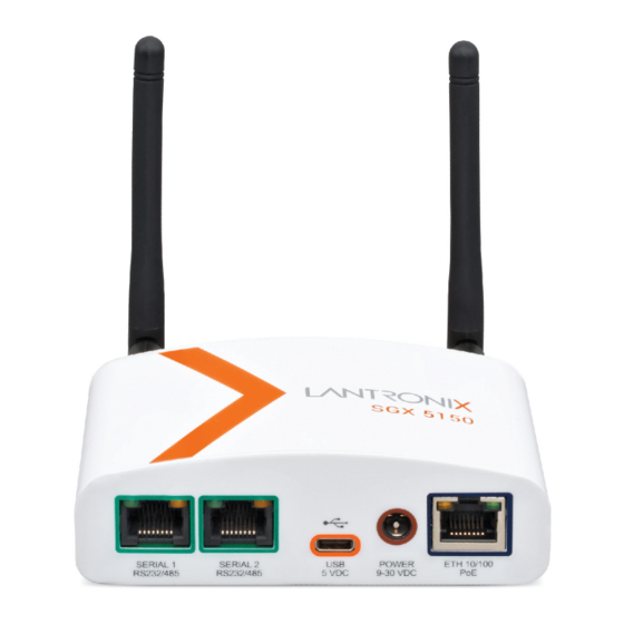
Page 24: Hardware Components
Figure 3-3 Back Panel Serial Interface One or two serial ports are available for the SGX 5150. Data rates can be configured for speeds between 300 and 921 kbaud. Hardware protocol options include the following: Two RJ45 RS232 Serial Ports, or ... -
Page 25: Usb Connection
3: Installation of the SGX 5150 Table 3-4 Serial RJ45 Connector Pinout and LEDs Pin Number Signal Name for RS-232 Signal Name for Signal Name for RS-422/485 (4 wire) RS485 2-Wire RTS (output from SGX) TX+ (output from SGX) TX+/RX+ DTR (output from SGX) Not used/do not connect. -
Page 26: Power
Connector SGX can provide VBUS 5V 0.5A out if configured as USB host, and powered by Lantronix provided wall adaptor, or PoE power source class 2 (hardware optional) Ethernet PoE PoE power module is optional RJ45 Connector Must provide class 2 PoE power source ... -
Page 27: Wi-Fi Protected Setup (Wps)
All OFF Wi-Fi Protected Setup (WPS) Using WPS, you have the option of connecting to SGX 5150 devices with a router or access point in a single operation instead of manually creating a profile with a network name (SSID), setting up wireless security parameters and updating the choice list. -
Page 28: Reset Button
Installing the SGX 5150 Be sure to place or mount the SGX 5150 gateway securely on a flat horizontal or vertical surface. The gateway comes with brackets for mounting it, for example, on a wall. If using AC power, do not use outlets controlled by a wall switch. -
Page 29: Figure 3-15 Sgx 5150 Dimensions In Inches (In) And Millimeters (Mm)
3. Mount or place the SGX 5150 gateway securely. 4. Supply power to the SGX 5150 and connect it to the user device by using the supplied type A to type C USB cable. As soon as you plug the gateway into power, it powers up automatically, the self-test begins, and LEDs would indicate the gateway’s status. -
Page 30: Optional Sgx 5150 Bracket
3: Installation of the SGX 5150 Optional SGX 5150 Bracket A bracket accessory for securing the SGX 5150 IoT device gateway can be purchased at the Lantronix Online Store at https://store.lantronix.com/ or by calling Lantronix Sales at 800-422- 7055. Purchased brackets will come with an installation guide. -
Page 31: Wireless Quick Connect
3: Installation of the SGX 5150 Wireless Quick Connect Continue with these steps for Wireless Quick Connect after installing the SGX 5150 IoT device gateway. 1. From your Wi-Fi device, connect to SSID sgx5150_*, where * is your gateway 12-digit serial number. -
Page 32: 4: Using Deviceinstaller
3. Expand the SGX folder by clicking the + symbol next to the folder icon. A list of available Lantronix SGX 5150 units appears. 4. Select a SGX 5150 unit by expanding its entry and clicking on its IP address to view its configuration. -
Page 33: Table 4-1 Sgx 5150 Configuration In Deviceinstaller
Version Online Status Non-configurable field. Displays the SGX 5150 unit’s status as Online, Offline, Unreachable (if the unit is on a different subnet), or Busy (the SGX 5150 unit is currently performing a task.) IP Address Non-configurable field. Displays the SGX 5150 unit’s current IP address. To change the IP address, click the Assign IP button on the DeviceInstaller menu bar. -
Page 34: Next Step
Next Step Now that the SGX 5150 unit has an IP address and other initial settings, you can configure it. 1. Double-click the unit in the list. Details about the unit display. 2. You have the following options: To configure the unit using a Web browser, click the Web Configuration tab. -
Page 35: 5: Configuration Using Web Manager
1. Open a standard web browser. Lantronix supports the latest versions of Internet Explorer®, Firefox®, Safari®, or Chrome™ web browsers. 2. Enter the IP address or host name of the SGX 5150 unit in the address bar. The IP address may have been assigned manually using DeviceInstaller (see Chapter 4: Using DeviceInstaller on page 32) or automatically by DHCP. -
Page 36: Status Page
5: Configuration Using Web Manager Status Page This page appears upon logging into Web Manager and when you click the Status tab. Figure 5-1 Status Page (Section 1 of 2) 5150 IoT Device Gateway User Guide... -
Page 37: Figure 5-2 Status Page (Section 2 Of 2)
5: Configuration Using Web Manager Figure 5-2 Status Page (Section 2 of 2) 5150 IoT Device Gateway User Guide... -
Page 38: Web Manager Components
5: Configuration Using Web Manager Web Manager Components The layout of a typical Web Manager page is below. Figure 5-3 Components of the Web Manager Page Header Menu Bar Status and/or Configuration Area Web Manager pages have these sections: The Status, Network, Diagnostics and Administration tabs located in the header at the top ... -
Page 39: Navigating Web Manager
5: Configuration Using Web Manager Navigating Web Manager The table below provides a shortcut to the various software features available for viewing and configuration through Web Manager. Table 5-5 Web Manager Pages Web Manager Page Description Page Status Shows product information, network, line, and tunneling settings. Access Point Allows you to configure an access point and shows the current operational state of existing access points. - Page 40 5: Configuration Using Web Manager Web Manager Page Description Page Processes Shows the processes currently running on the system. Protocol Stack Lets you perform lower level network stack-specific activities. QuickConnect Lets you change configuration settings for the Quick Connect. Quick Setup Shows the quick setup configuration options for the device.
-
Page 41: 6: Network Settings
Network Settings Network settings for the SGX 5150 can be viewed and modified under the Network tab in the Web Manager user interface. This chapter describes the following network settings: Access Point Bridge Wired (eth0) Network Wireless (wlan0) Network ... -
Page 42: To View Or Configure Access Point Settings
SGX 5150 gateway. If Auto Detect IP Address is enabled, then the SGX 5150 gateway will attempt to learn the IP Address by using the source or destination IP address of packets arriving on the Ethernet interface. -
Page 43: Bridge Status And Configuration
If Enabled, the SGX 5150 can no longer be accessed via telnet or web manager from a PC and is invisible to the network. If Disabled, the SGX 5150 will be accessible to a PC on the network via telnet or Web Manager. -
Page 44: To View Or Configure Bridge Settings
Ethernet configuration. Local ports must be configured to distinguish network traffic destined for the SGX 5150 gateway. Any port configured on the SGX 5150 gateway must be different from those in use by services on the bridged client. -
Page 45: Interface Status And Configuration
Select to enable or disable. DHCP Client Select to turn On or Off. At boot up, after the physical link is up, the SGX 5150 unit will attempt to obtain IPv4 settings from a DHCP server and will periodically renew these settings with the server. -
Page 46: To Configure Network Interface Settings
Select to enable or disable. IPv6 DHCP Client Select to turn On or Off. At bootup, after the physical link is up, the SGX 5150 unit will attempt to obtain IPv6 settings from a DHCPv6 server and will periodically renew these settings with the server. -
Page 47: Link Status And Configuration
6: Network Settings Using XML Include in your file: <configgroup name= “interface" instance="eth0"> Link Status and Configuration Table 6-4 displays the wired link status and configuration information. The view-only status information is available on the Wired (eth0) Network Ethernet Link page. This same information is configurable on the Wired (eth0) Network Ethernet Link Configuration page. -
Page 48: To View And Configure Wired Network Qos Settings
6: Network Settings Network Control and Internetwork Control are typically used for network control packets such as ICMP and have the highest priorities. Move bandwidth allocation is a minimum 5% each to Network control. Voice: Bandwidth allocation is minimum 30%. ... -
Page 49: Wired (Eth0) Network Failover
Wireless (wlan0) Network The wireless network pages are used to configure and view the status of the wireless (wlan0) interface and link on the SGX 5150 gateway. To see the effect of these items after a reboot, view the Status page. -
Page 50: Table 6-7 Wireless (Wlan0) Interface Configuration
Select to enable or disable. DHCP Client Select to turn On or Off. At boot up, after the physical link is up, the SGX 5150 unit will attempt to obtain IPv4 settings from a DHCP server and will periodically renew these settings with the server. -
Page 51: To View Or Configure Wireless Network Interface Settings
Description IPv6 DHCP Client Select to turn On or Off. At bootup, after the physical link is up, the SGX 5150 unit will attempt to obtain IPv6 settings from a DHCPv6 server and will periodically renew these settings with the server. -
Page 52: Table 6-8 Wireless (Wlan0) Link Configuration
For example, if the external AP is configured for channel 36 with 40 MHz support enabled the SGX 5150 may indicate a connection on channel 38. It has also been observed with the Netgear WNDAP350 AP (configured with 40 MHz channel support) that the SGX 5150 may establish a connection with either of the bonded 20 MHz channels (whether or not it is included in the 'Scanning Channel List'.) For... -
Page 53: To View Or Configure Network Link Settings
6: Network Settings Field/Button Description WiFi Direct GO Mode Select to enable or disable. If enabled, WPS issues the credentials when the client device indicates that it wishes to connect with our device. No password is required. Go to Wi-Fi Protected Setup (on page 63) to setup WPS. -
Page 54: To View Or Configure Wireless Network Qos Settings
(essentially a ping against a known host). If the remote host is determined to be not reachable, the SGX 5150 gateway will failover to the Ethernet interface. If the remote host is determined to be reachable, the gateway will failback to the Wi-Fi interface. -
Page 55: To View Or Configure Wireless Network Failover Settings
Priority ranges from 0-10. The IP stack will give the interface with the lowest numerical value highest priority and the highest numerical values lowest priority when sending data. This setting only applies when the SGX 5150 gateway is not in bridging mode and both interfaces are connected to the same IP subnet. - Page 56 Description DHCP Client Select to turn On or Off. At boot up, after the physical link is up, the SGX 5150 unit will attempt to obtain IPv4 settings from a DHCP server and will periodically renew these settings with the server.
-
Page 57: To Configure Network Interface Settings
6: Network Settings Field/Button Description IPv6 Default Gateway Enter the default IPv6 default gateway. IPv6 Domain Enter the domain name suffix for the interface. Note: This setting will be used when either Static IP or Auto IP is active, or if DHCP/BOOTP is active and no Domain Suffix was acquired from the server. -
Page 58: To View And Configure Wired Network (Usb) Qos Settings
Wired (usb0) Network Failover The SGX 5150 device gateway provides a USB network failover, in the form of a "dead remote host reachability" mechanism (essentially a ping against a known host). If the remote host is determined to be not reachable, the SGX 5150 gateway will failover to the Wi-Fi interface. If the remote host is determined to be reachable, the gateway will failback to the USB interface. -
Page 59: To View And Configure Wired (Usb0) Network Failover Settings
Interval Indicate the interval in which to test reachability Failover Threshold Indicate the allowed number of failed pings – after which the SGX 5150 gateway will failover to the wlan0 interface. Failback Threshold Indicate the number of successful pings – after which the SGX 5150 gateway will failback to the Ethernet interface. -
Page 60: Icmp Settings
6: Network Settings Using the CLI To enter the command level: enable > config > ip Using XML Include in your file: <configgroup name=”ip”> ICMP Settings This page contains lower level ICMP Network Stack specific configuration items. Table 6-16 ICMP Protocol Stack Settings Protocol Stack ICMIP Description Settings... -
Page 61: To Configure Arp Network Stack Settings
6: Network Settings To Configure ARP Network Stack Settings Using Web Manager To configure ARP protocol settings, on the Network page, click Protocol Stack > ARP. Using the CLI To enter the command level: enable > config > arp ... - Page 62 6: Network Settings VPN Setting Description Interface Select the interface to use to connect to VPN Gateway. eth0 usb0 wlan0 Remote Network Endpoint Enter the remote VPN Gateway’s IP Address. Subnet Enter the subnet behind the VPN Gateway. Enter the identifier expected to receive from the remote host during Phase 1 negotiation.
-
Page 63: Configuring Vpn Settings
Wi-Fi Protected Setup Using Wi-Fi® protected setup (WPS), you have the option of connecting the SGX 5150 unit to a router or access point in a single operation instead of manually creating a profile with a network name (SSID), setting up wireless security parameters and updating the choice list. You may setup WPS through pin or push button functionality through Web Manager or through CLI. -
Page 64: To Show Wps Status
WLAN Scan/QuickConnect Going to this page initiates a scan of wireless networks within range of the SGX 5150 unit and allows users to add a WLAN profile after testing it. This list refreshes automatically every 15 seconds. There is also an option to automatically update the scan results every 60 seconds, which is disabled by default. -
Page 65: To View Wlan Link Scan And Status Information
A maximum of eight profiles can exist on the SGX 5150 unit at a time. All enabled profiles are active. The SGX 5150 unit supports dynamic profiles and prioritization of the profiles. Dynamic Profiles are created using WPS or Quick Connect. Profiles are assigned numbers based on priority. For example, dynamic profiles list in reverse order of creation, followed by choice-list profiles, then any remaining profiles. -
Page 66: Configuring Wlan Profile Settings
6: Network Settings WLAN Profile Settings Description Delete (check box) Check the checkbox to the right of the WLAN profile listed right and click the Submit button which appears, to delete the specific profile. Name Click an existing WLAN profile listed under the Name column to reveal the (link to WLAN profile) configuration options as shown in Table 6-22 Individual WLAN Profile... - Page 67 authentication server that is part of the network. The RADIUS server matches the credentials sent by the SGX 5150 unit with an internal database. If IEEE 802.1X is selected under authentication type, select the protocol to use to authenticate the WLAN client.
- Page 68 IEEE 802.1x authentication, and PEAP settings are selected. Validate Certificate If EAP-TLS is selected, validate the certificate installed on the SGX 5150 gateway by selecting Enabled in the Validate Certificate field which appears. Validates the certificate installed on the SGX 5150 gateway with the one received from the RADIUS server.
-
Page 69: 7: Filesystem
File Transfer and Modification Files can be transferred to and from the SGX 5150 device via the TFTP protocol. This can be useful for saving and restoring XML configuration files. Files can also be uploaded via HTTP. Table 7-2 File Transfer Settings... -
Page 70: To View, Transfer, Or Modify Filesystem Files
7: Filesystem File Transfer Settings Description Remote File Enter the name of the file at the remote location that is to be stored locally (“get’) or externally (“put”). Host Enter the IP address or name of the host involved in this operation. Port Enter the number of the port involved in TFTP operations. -
Page 71: 8: Diagnostics
Diagnostics Diagnostic settings for the SGX 5150 unit can be viewed and modified under the Diagnostics tab in the Web Manager user interface. This chapter describes the following diagnostic settings: Hardware IP Sockets Memory Ping ... -
Page 72: Hardware
8: Diagnostics Wireless (wlan0) Network interface settings according to instructions at Wireless (wlan0) Network (on page 49). Using CLI To enter CLI command level: enable > dns Using XML Not applicable. Hardware View the CPU type, CPU speed, RAM size and flash size of the hardware on this Web Manager page. -
Page 73: Log
You can use Ping to test connectivity to a remote host. Table 8-3 Ping Configuration IP Socket Description Host Enter the IP address or host name for the SGX 5150 unit that you want to ping. 5150 IoT Device Gateway User Guide... -
Page 74: To Ping A Remote Host
Not applicable. Processes The SGX 5150 unit shows all the processes currently running on the system. It shows the process ID (PID), parent process ID (PPID), user, CPU percentage, percentage of total CPU cycles, and process command line information. -
Page 75: Threads
Traceroute You can use traceroute to trace a packet from the SGX 5150 unit to an Internet host. A traceroute shows how many hops the packet requires to reach the host, and how long each hop takes. This information can be helpful to diagnose delays for a web page that loads slowly. -
Page 76: 9: Administration
Administration Administrative features for the SGX 5150 device gateway are organized beneath the Administration tab in the Web Manager user interface. This chapter describes the following administrative settings: Actions Applications Clock Discovery Email ... -
Page 77: Actions
9: Administration Actions Table 9-1 contains the configuration options for all the alarms and reports listed above. Table 9-1 Action Settings Action Settings Description Delay Use Delay to defer alarm processing. Alarm actions will not be executed if the cause is corrected within this time. -
Page 78: To Configure Action Settings
Python™ is a dynamic, object-oriented programming language that can be used for developing a wide range of software applications. The Lantronix SGX 5150 includes the installation of Python interpreter, making it easy to load and run custom Python scripts on your device. -
Page 79: Applications
This plugin provides a one-click upload of a file to an FTP server. Debugging and testing on the SGX 5150 easier because SGX 5150 products have an FTP server through which to upload files into the file system. Applications... -
Page 80: To Configure Application Settings
The command line interface (CLI) settings allow you to control how users connect to and interact with the command line of the SGX 5150 unit. It is possible to configure access via the Telnet and SSH protocols, in addition to general CLI options. -
Page 81: To View And Configure Basic Cli Settings
UTC. The UTC Offset of the form HHMM (H = hour, M = minute) is applied to the UTC time to get the local time. The SGX 5150 gateway will make seasonal time changes required for Daylight Savings Time. -
Page 82: To Specify A Clock-Setting Method
Network discovery allows your computer to locate other computers and devices on the network. This setting also allows other computers to see your computer. The current statistics and configuration options for device discovery, including UPnP query port, are available for the SGX 5150 unit. Table 9-5 Discovery Settings Discovery Settings... -
Page 83: Email
Note: The following section describes the steps to view and configure Email 1 settings; these steps apply to other emails available for the SGX 5150 gateway. Using Web Manager To view Email statistics, on the Administration page, click Email > Statistics. -
Page 84: Ftp
9: Administration The FTP protocol can be used to upload and download user files, and upgrade the SGX 5150 firmware. A configurable option is provided to enable or disable access via this protocol. Table 9-7 FTP Settings FTP Settings Description... -
Page 85: Wan
use the gateway normally. Gateway: allows the gateway to be used as a router with NAT. Router: allows the SGX 5150 gateway to be used as a router without NAT. Firewall Select to enable or disable firewall: Enabled: enables the SGX 5150 gateway firewall. -
Page 86: Port Forwarding
(LAN). Port Forwarding rules apply to inbound traffic and will not work if the SGX 5150 gateway is not reachable or traffic to certain ports is blocked before it reaches the gateway. -
Page 87: To Configure Gateway Port Forwarding Settings
Using XML Include in your file: <configgroup name="gateway"> <configitem name="port forwarding" instance="<number>"> Static Routes Allows the user to add routes to the SGX 5150 gateway routing table. Table 9-12 Static Route Setting Routes Static Route Settings Description Enabled Enables the static route... -
Page 88: Dhcp Server
<number> Using XML Include in your file: <configgroup name ="gateway"> <configitem name="static routes" instance="<number>" DHCP Server Allows the user to configure the SGX 5150 gateway as a DHCP server. Table 9-14 DHCP Settings DHCP Settings Description Configuration Lease time Duration for which lease is initially assigned. -
Page 89: Static Lease Listing
Static Lease Listing The SGX 5150 gateway also provides the ability to pre-assign specific IP addresses to connected devices using static leases. This would ensure that the connected device (identified by the MAC address) always gets the same IP address even while using DHCP. -
Page 90: To Configure Gateway Routing Protocol Settings
Virtual IP The SGX 5150 IoT device gateway allows the configuration of Virtual IP addresses. Virtual IP is a means to map an externally visible IP address to LAN-side IP addresses. SGX 5150 units will support creating up to three virtual IP address mappings. -
Page 91: To Configure Gateway Virtual Ip
Include in your file: <configgroup name = "virtual ip"> GRE tunneling is available on the SGX 5150, providing more capabilities than IP-in-IP tunneling. For example, it supports transporting multicast traffic and IPv6 through a GRE tunnel. Table 9-20 GRE Settings... -
Page 92: To Configure Gre Settings
This configuration option is only available when SSH is selected for Protocol. Remote Address Enter an IP address for the host to which the SGX 5150 gateway will connect. Remote Port Enter the port on the host to which the SGX 5150 gateway will connect. -
Page 93: Http
HTTP defines how messages are formatted and transmitted. It also defines the actions Web servers and browsers take in response to different commands. HTTP Authentication enables the requirement of user names and passwords for access to the SGX 5150 gateway. Interface Status, Configuration and Authentication... -
Page 94: To View Or Configure Http Authentication
9: Administration HTTP Settings Description Max Log Entries Set the maximum number of HTTP server log entries. Only the last Max Log Entries are cached and viewable. Log Format Set the log format string for the HTTP server. Follow these Log Format rules: %a - remote IP address (could be a proxy) ... -
Page 95: To Configure Http Authentication
Using XML Include in your file: <configgroup name="http authentication uri"> Line The SGX 5150 units offer 1 or 2 serial ports which use standard RS232/RS485 interfaces. The lines can be configured to operate in the following modes: RS232 ... -
Page 96: Table 9-24 Line Configuration Settings
9: Administration Table 9-24 for the line settings that can be modified on the Line 1 - Configuration page. See Table 9-25 for the line settings that can be established on the Line 1 - Command Mode page. Table 9-24 Line Configuration Settings Line Settings Description Name... -
Page 97: To View And Configure Line Configuration And Command Mode
Include in your file: <configgroup name="line" instance=”1”> MACH10 The SGX 5150 gateway comes integrated with MACH10® cloud platform to allow for the remote management of devices. To set up the MACH10 client, you need to configure the following settings: MACH10 Client - to connect to the MACH10 cloud platform. -
Page 98: To Configure Mach10 Line 1 Or Line 2
9: Administration Table 9-26 MACH10 Client Configuration MACH10 Client Description State Click to enable or disable the MACH10 client. Status Update Enter the Status Update Interval in minutes. Interval Content Check Enter the Content Check Interval in hours. Interval Apply Firmware Select to enable or disable the automatic setting. -
Page 99: To Configure Mach10 Usb 1
9: Administration This page displays the configuration and status for MACH10 Line client. Table 9-28 MACH10 Line MACH10 Line Description State Click to enable or disable the MACH10 line client. Project Tag Enter the MACH10 Project Tag name. Status Update Enter the Status Update Interval in minutes. -
Page 100: Modbus
Modbus The SGX 5150 IoT device gateway operates as a master device that connects to slave devices. The Modbus ASCII/RTU based serial slave devices can be connected via the Ethernet through an existing Modbus TCP/IP network. Any device having access to a given Modbus implementation will be able to perform full range of operations that the implementation supports. -
Page 101: To View And Configure The Modbus Server
An RDF Site Summary (RSS) syndication feed is served by the HTTP Server. This feed contains up-to-date information regarding the configuration changes that occur on the SGX 5150 gateway. Specifying the RSS Feed to be Persistent results in the data being stored on the filesystem. The file used is /cfg_log.txt. -
Page 102: To Configure Rss Settings
9: Administration RSS Settings Description Persistent Click to select whether to turn the RSS Feed is Persistent: On or Off. Max Entries Enter the numerical value of maximum RSS feed entries to be cached and viewable. Data Click View to view existing RSS data. ... -
Page 103: Snmp Settings
Specify a system location for the SNMP setting. Lantronix MIB File Click the Lantronix MIB file name to save and load it into the MIB browser and trap receiver. This is the base MIB file for Lantronix products. Load or compile this file first. -
Page 104: To Configure Snmp Settings
Configuration is required when the SGX 5150 device is either (1) the SSH server or (2) an SSH client. The SSH server is used by the CLI (Command Mode) and for tunneling in Accept Mode. -
Page 105: Ssh Server: Authorized Users
Click the Submit button after changes are made in the above Create New Keys fields. Note: SSH Keys from other programs may be converted to the required SGX 5150 format. Use Open SSH to perform the conversion. SSH Server: Authorized Users The SSH Server Authorized Users are used by all applications that play the role of an SSH Server during Tunneling in Accept Mode. -
Page 106: Ssh Client: Users
TThe SSH Client Users are used by all applications that play the role of an SSH Client during Tunneling in Connect Mode. To configure the SGX 5150 as an SSH client, an SSH client user must be both configured and also exist on the remote SSH server. -
Page 107: To Configure Ssh Settings
9: Administration SSH Settings Description Key Type Select a bit length for the key: Add/Edit (button) Click the Add/Edit button after changes are made in the above SSH Server: Users fields. Table 9-40 Create New Keys SSH Setting Description Username Enter the Username for the new key. -
Page 108: Ssl
Web server, and also for wireless authentication. SSL certificates identify the SGX 5150 unit to peers and are used with some methods of wireless authentication. Provide a name at upload time to identify certificates on the SGX 5150 unit. -
Page 109: To Configure An Ssl Credential To Use An Uploaded Certificate
SGX 5150 unit belongs. Common Name Enter a network name for the SGX 5150 unit when installed in the user’s network (usually the fully qualified domain name). It is identical to the name that is used to access the SGX 5150 unit with a web browser without the prefix . -
Page 110: To Configure An Ssl Credential To Use A Self-Signed Certificate
9: Administration 6. Identify the New Certificate Type selected. If you select SSL authority, RSA, or DSA certificates, select PEM or PKCS7. If the Web Manager determines that the certificate is an Authority Certificate type, the New Certificate Type field updates to PKCS12 automatically. For PKCS12 certificates, enter a password. -
Page 111: To Upload An Authority Certificate
Upon leaving the factory this certificate and the underlying secret key is the same for all SGX 5150 units and will not match the network configuration where it is installed. The certificate’s underlying secret key is also used for securing the SSL handshake. -
Page 112: Syslog
Common Name Enter the network name of the SGX 5150 unit once it is installed in the user’s network (usually the fully qualified domain name). It is identical to the name that is used to access the SGX 5150 unit with a web browser without the prefix http:// . -
Page 113: System
The redirect will not work as expected if the IP Address of the SGX 5150 gateway changes after reboot. Restore Factory Defaults Click the Factory Defaults button to restore the SGX 5150 gateway to the original factory settings. All configuration will be lost. The SGX 5150 unit automatically reboots upon setting back to the defaults. -
Page 114: To Access System Settings
System Settings Description Standalone Firmware Click Reboot to Standalone Firmware Installer to reboot the SGX 5150 Installer gateway to a standalone firmware installer mode. When the SGX 5150 gateway is rebooted, your browser should be refreshed and redirected to the firmware installer page after 30 seconds. -
Page 115: To Configure The Terminal Network Connection
Note: The following section describes the steps to view and configure terminal line 1 settings; these steps apply to terminal line 2 and terminal line 3 of the SGX 5150 gateway. Using Web Manager To configure a particular Terminal Line, click Administration in the header and select ... -
Page 116: Tunnel
Note: The following section describes the steps to view and configure Tunnel 1 settings; these steps apply to other tunnel instances of the SGX 5150 gateway. Tunnel Statistics Tunnel statistics contains data counters, error counters, connection time and connection information. -
Page 117: To Configure Tunnel Serial Settings
9: Administration Terminal Serial Settings Description (continued) Select the conditions in which the Data Terminal Ready (DTR) control signal on the serial line are asserted. Choices are: Unasserted TruPort = the DTR is asserted whenever either a connect or an accept mode ... -
Page 118: To Configure Tunnel Packing Mode Settings
Accept Mode In Accept Mode, the SGX 5150 listens (waits) for incoming connections from the network. A remote node on the network initiates the connection. The configurable local port is the port the remote device connects to for this connection.There is no remote port or address. Supported serial lines and associated local port numbers progress sequentially in matching value. -
Page 119: Table 9-49 Tunnel Accept Mode Settings
TCP Keep Alive Enter the time, in milliseconds, the SGX 5150 waits during a silent TCP connection before checking if the currently connected network device is still on the network. If the unit gets no response after 1 attempt, it drops the connection. -
Page 120: To Configure Tunnel Accept Mode Settings
Include in your file: <configgroup name="tunnel accept" instance="1"> Connect Mode In Connect Mode, the SGX 5150 continues to attempt an outgoing connection on the network, until established (based on which connection method is selected in the configuration described in 5150 IoT Device Gateway User Guide... -
Page 121: Table 9-50 Tunnel Connect Mode Settings
(TCP or UDP). When established, Connect Mode is always on. Enter the remote station as an IPv4 or IPv6 address or DNS name. The SGX 5150 will not make a connection unless it can resolve the address. For Connect Mode using UDP, the SGX 5150 accepts packets from any device on the network. -
Page 122: Table 9-51 Host Settings
9: Administration Tunnel Connect Mode Description Settings (continued) Block Serial Set whether Block Serial is enabled for debugging purposes. Choices are: Enabled = If Enabled, incoming characters from the Serial Line will not be forwarded to the network. Instead, they will be buffered and will eventually flow off the Serial Line if hardware or software flow control is configured. -
Page 123: To Configure Tunnel Connect Mode Settings
If more than one host is configured, a Host Mode option appears. Host Mode controls how multiple hosts will be accessed. For the SGX 5150, the Connect Mode supports up to 32 hosts. Hosts may be accessed sequentially or simultaneously: Sequential –... -
Page 124: Host List Promotion
Simultaneous – A tunnel will connect to all hosts accepting a connection. Simultaneous connections occur at the same time to all listed hosts. The SGX 5150 gateway can support a maximum of 64 total aggregate connections. Host List Promotion This feature allows Host IP promotion of individual hosts in the overall sequence. -
Page 125: Modem Emulation
Some older equipment is designed to attach to a serial port and dial into a network with a modem. This equipment uses AT commands to control the connection. For compatibility with these older devices on modern networks, the SGX 5150 mimics the behavior of the modem. Table 9-53 Tunnel Modem Emulation Settings... -
Page 126: To Configure Tunnel Modem Emulation Settings
9: Administration To Configure Tunnel Modem Emulation Settings Using Web Manager To configure the Modem Emulation for a specific tunnel, on the Administration page, click Tunnel > Tunnel 1 > Modem Emulation. Using the CLI To enter the Tunnel 1 Modem command level: enable > tunnel 1 > modem ... -
Page 127: To Configure Usb Settings
9: Administration USB Settings Description Line Mode Select the USB port mode from the drop-down menu. The USB port can be configured in one of the following: Ethernet Device, Serial Device, or Host. Host mode supports connecting Mass Storage and Serial devices. Gap Timer Indicate the gap time in milliseconds. -
Page 128: User Management
Create new user login, password and roles here. Admin-created users can be deleted or altered in the Current Users list (Table 9-57). Up to 8 user accounts can be created to access the SGX 5150 gateway. New User Settings Description Username Enter the Username of the new user. -
Page 129: Table 9-59 Current Roles List
Table 9-59 Current Roles List The system-defined default roles that come with the SGX 5150 gateway along with any Admin- created user roles are listed here. Admin-created custom roles can be deleted or altered. Current Role... -
Page 130: To Configure User Management
The exported file can be modified and imported to update the configuration on this SGX 5150 gateway or another. XML records can also be exported to browser window or to a download link on the SGX 5150 gateway. Notice that by default, all Groups to Export are checked except some pertaining to the network configuration;... -
Page 131: To Export Configuration
9: Administration Selection of Lines to Export filters instances to be exported are in the line, relay, serial, terminal, and groups. To Export Configuration By default, all settings groups are checked. Using Web Manager 1. In the Web Manager, click the Administration tab. 2. -
Page 132: To Import Configuration
9: Administration Using Web Manager 1. In the Web Manager, click the Administration tab. 2. Click XML. 3. Click Export Status. 4. Select where to send exported status information: Export to browser sends the information into a separate web window which appears. ... -
Page 133: Table 9-61 Configuration From Filesystem
Table 9-61 Configuration from Filesystem Setting Description Filename Enter the name of the file on the SGX 5150 unit (local to its filesystem) that contains XCR data. Lines to Import Select filter instances to be imported in the line, serial, tunnel and terminal groups. -
Page 134: Quick Setup
Bridging IPv6 Address Enter the bridging IPv6 address Auto Detect IPv4 Check the radio button to enable it. If checked, the SGX 5150 gateway will Address attempt to learn the IP Address by using the source or destination IP address of packets arriving on the Ethernet interface. -
Page 135: Table 9-66 Available Networks
9: Administration Setting Description DHCP Client Select to turn on or off IPv6 State Select to enable or disable the state IPv6 DHCP Client Select to turn on or off IPv6 Auto Select to turn on or off Configuration Table 9-66 Available Networks Setting Description Refresh scan results... -
Page 136: A: Lantronix Technical Support
A: Lantronix Technical Support Lantronix offers many resources to support our customers and products at http://www.lantronix.com/support. For instance, you can ask a question, find firmware downloads, access the FTP site and search through tutorials. At this site you can also find FAQs, bulletins, warranty information, extended support services and product documentation. -
Page 137: B: Compliance
B: Compliance (According to ISO/IEC Guide and EN 45014) Manufacturer’s Name & Address: Lantronix, Inc. 7535 Irvine Center Drive, Suite 100, Irvine, CA 92618 USA Product Name Model: SGX 5150 IoT Device Gateway Conforms to the following standards or other normative documents:... -
Page 138: Figure B-1 Eu Declaration Of Conformity
B: Compliance Figure B-1 EU Declaration of Conformity 5150 IoT Device Gateway User Guide... -
Page 139: Table B-2 Eu Declaration Of Conformity
Lantronix declara que este SGX 5150 IoT device gateway está conforme com os [Portuguese] requisitos essenciais e outras disposições da Directiva RED 2014/53/EU. Slovensko [Slovenian] Lantronix izjavlja, da je ta SGX 5150 IoT device gateway v skladu z bistvenimi zahtevami in ostalimi relevantnimi določili direktive RED 2014/53/EU. Slovensky [Slovak] Lantronix týmto vyhlasuje, že SGX 5150 IoT device gateway spĺňa základné... -
Page 140: Table B-3 Country Transmitter Ids
Suomi [Finnish] Lantronix vakuuttaa täten että SGX 5150 IoT device gateway tyyppinen laite on direktiivin RED 2014/53/EU oleellisten vaatimusten ja sitä koskevien direktiivin muiden ehtojen mukainen. Svenska [Swedish] Härmed intygar Lantronix att denna SGX 5150 IoT device gateway står I överensstämmelse med de väsentliga egenskapskrav och övriga relevanta... -
Page 141: Sgx 5150 Regulatory Domains
SGX 5150 Regulatory Domains Table B-5 20 MHz Channels Frequency Channel USA/Canada European Japan Union (U/US parts) (J/JS parts) E/ES parts) 2.4 GHz 2412 2417 Band 2422 2427 2432 2437 2442 2447 2452 2457 2462 2467 2472 2484 5 GHz Band 5180... -
Page 142: Rohs, Reach And Weee Compliance Statement
1. Models are only for use in their respective regions. Part numbers ending in U/US for US/ Canada, E/ES for European Union, J/JS for Japan. For other countries, user should confirm channel compatibility. SGX 5150 has not been certified in all countries. 2. Frequencies from 5150 MHz to 5250 MHz for indoor use only.
Need help?
Do you have a question about the SGX 5150 and is the answer not in the manual?
Questions and answers