Table of Contents
Advertisement
Quick Links
POWER VENTER KIT INSTALLATION
OPTIONS CA1, CA2, AND CA3 FOR UNIT HEATER MODELS F AND B
Please read all information in this manual thoroughly before installing the power venter kit. Pay attention to all
dangers, warnings, cautions, and notes highlighted in this manual. Safety markings should not be ignored and are
used frequently throughout to designate a degree or level of seriousness.
DANGER: A danger statement describes a potentially hazardous situation that if not avoided, will result in severe
personal injury or death and/or property damage.
WARNING: A warning statement describes a potentially hazardous situation that if not avoided, can result in severe
personal injury and/or property damage.
CAUTION: A caution statement describes a potentially hazardous situation that if not avoided, can result in minor
or moderate personal injury and/or property damage.
NOTE: A note provides important information that should not be ignored.
• Failure to follow safety warnings exactly and/or improper installation, adjustment, alteration,
service, or maintenance can result in dangerous operation, serious injury, death, or equipment/
property damage.
• The information listed in these instructions must be followed during the installation, service,
and operation of this unit. Read the installation, operation, and maintenance instructions
thoroughly before installing or servicing this equipment. Unqualified individuals should not
attempt to interpret these instructions or install this equipment.
• The gas burner in all Reznor gas-fired equipment is designed and equipped to provide safe,
complete combustion. However, if the installation does not permit the burner to receive the
proper supply of combustion air, complete combustion may not occur. The result is incomplete
combustion which produces carbon monoxide, a poisonous gas that can cause death. Safe
operation of indirect-fired gas burning equipment requires a properly operating vent system
which vents all flue products to the outside atmosphere. FAILURE TO PROVIDE PROPER
VENTING WILL RESULT IN A HEALTH HAZARD WHICH COULD CAUSE SERIOUS PERSONAL
INJURY OR DEATH.
• Always comply with the combustion air requirements in the installation codes and instructions.
Combustion air at the burner should be regulated only by manufacturer-provided equipment.
NEVER RESTRICT OR OTHERWISE ALTER THE SUPPLY OF COMBUSTION AIR TO ANY
HEATER. Indoor units installed in a confined space must be supplied with air for combustion
as required by Codes and in the heater installation manual. MAINTAIN THE VENT SYSTEM IN
STRUCTURALLY SOUND AND PROPERLY OPERATING CONDITION.
This power venter kit is designed for use only with Reznor® models F and B unit heaters and
is not applicable to other Reznor brand products or to appliances not manufactured as Reznor
products.
DO NOT DESTROY. PLEASE READ CAREFULLY. KEEP IN A SAFE PLACE FOR FUTURE REFERENCE.
IMPORTANT SAFETY INFORMATION
⚠ DANGER ⚠
⚠ WARNING ⚠
Revision: I-F-B-PV (03-21) 97967-B
Supersedes: I-F&B-PV (09-20) 97967-A
Advertisement
Table of Contents

Subscribe to Our Youtube Channel
Related Manuals for Reznor CA1


Summary of Contents for Reznor CA1
- Page 1 STRUCTURALLY SOUND AND PROPERLY OPERATING CONDITION. ⚠ WARNING ⚠ This power venter kit is designed for use only with Reznor® models F and B unit heaters and is not applicable to other Reznor brand products or to appliances not manufactured as Reznor products.
-
Page 2: General Information
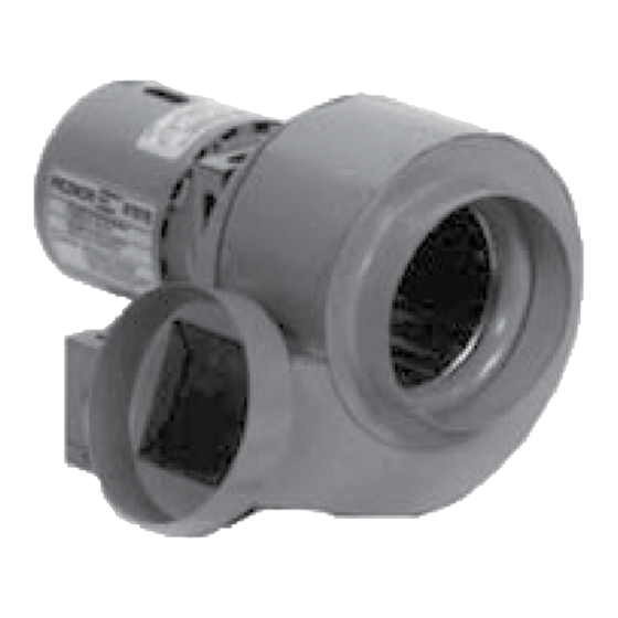
NOTE: When installation of the power venter is complete, place this instruction booklet in the instruction envelope supplied with the heater. It is important that this booklet be kept for future reference. Application The power venter is a motorized vent exhauster designed to permit the operation of Reznor gravity-vented model F ®... -
Page 3: Kit Installation
Table 2. Parts Bag Components Component Description Quantity Screw Sheet metal, #10 × 1/2-inch 11813 Wire connector Twist-on, orange, Ideal #3-0273 16354 T&B #253 16199 Box connector 90-degree 1417 Anti-short, red 16358 Bushing Open/closed, black, Heyco #OCB-625 148086 Wire assembly Brown 98364 Blue, 60 inches long... - Page 4 KIT INSTALLATION—CONTINUED b. Insert screw removed in step 3a through slotted hole in hanger bracket—top hole for unit sizes 025–125, Figure 2, DETAIL A. bottom hole for unit sizes 130–400—and secure bracket to inner side panel as shown in Slide hanger bracket up against top of inner side panel, align clearance hole and cage nut, and tighten screw. HANGER ROD LOCKNUT CLEARANCE HOLE...
- Page 5 FLUE ADAPTER ASSEMBLY FLUE RESTRICTOR HOLES FLUE ADAPTER ASSEMBLY HOLES UNIT SIZE 125 FLUE RESTRICTOR HOLES DETAIL A Figure 3. Flue Restrictor and Flue Adapter Assembly Installation 5. Remove existing flue collar assembly: a. For unit sizes 025, 050, 075, 100, 130, 165, and 200: remove and discard factory-installed flue collar assembly (if heater was manufactured before OCT 1989, it has fixed vertical vent outlet so there is nothing to remove).
- Page 6 KIT INSTALLATION—CONTINUED 7. Install venter sub-assembly: NOTE: The venter sub-assembly is assembled and wired at the factory. It includes the venter wheel and housing, the motor, a junction box, an airflow switch, a time delay relay, and on unit sizes 300 and 400, a capacitor.
- Page 7 THREADED ELECTRICAL SUPPLY ENTRANCE WIRING ACCESS PANEL CONDUIT PLUG Figure 5. Conduit Installation f. Depending on direction of vent, position straight and 90-degree box connectors at knockouts in venter junction Figure 6, DETAIL A. Ensure that straight connector is positioned so that it is possible to box as shown in tighten holding screw.
- Page 8 KIT INSTALLATION—CONTINUED Figure 7. Wiring Diagram of Model F or B Unit Heater with Optional Power Venter I-F-B-PV (03-21) 97967-B...
- Page 9 c. Feed two line voltage wires (black and white) into venter junction box through 90-degree box connector and tighten cover on connector being careful not to punch hole in conduit. Feed four low voltage wires (brown, yellow, blue, and orange) into venter junction box through straight box connector and tighten holding screw. d.
-
Page 10: Vent Installation
KIT INSTALLATION—CONTINUED 10. Install warning label: a. Select location—not on hot surface—on fan back panel or blower adapter back to affix warning label from kit. b. Wipe surface with clean, dry cloth. c. Peel adhesive backing from label and adhere it to heater. NOTES: ADDITIONAL INSTALLATION NOTES: •... - Page 11 • Any commercially available cap listed for use as a vent cap for fuel burning appliances is acceptable. For optimum stability under wind conditions, a Reznor option CC1 vent cap is recommended. • Many local codes require the use of double-wall (type B) vent for the portion of vent pipe (terminal) on the outside of the building.
- Page 12 VENT INSTALLATION—CONTINUED Vent Termination (Vent Pipe and Vent Cap)—Continued Figure 9. Vertical Vent Termination—Single-Wall Vent Run and Single-Wall Terminal End Figure 10. Vertical Vent Termination—Single-Wall Vent Run and Double-Wall Terminal End I-F-B-PV (03-21) 97967-B...
- Page 13 Figure 11. Horizontal Vent Termination—Single-Wall Vent Run and Single-Wall Terminal End Figure 12. Horizontal Vent Termination—Single-Wall Vent Run and Double-Wall Terminal End I-F-B-PV (03-21) 97967-B...
- Page 14 VENT INSTALLATION—CONTINUED Vent Termination Clearances ⚠ DANGER ⚠ • To prevent combustion products from entering the occupied space, all vent terminations must be positioned or located away from fresh air intakes, doors, and windows. Failure to comply could result in severe personal injury or death and/or property damage. •...
-
Page 15: Operational Testing
OPERATIONAL TESTING Test power venter and heater for proper operation as follows: ⚠ DANGER ⚠ Do not put a heater into service that does not properly exhaust flue gases to the outside atmosphere. ⚠ WARNING ⚠ The power venter must be installed and wired in accordance with these installation instructions. The pressure switch MUST be wired in series with the thermostat to interrupt the main gas valve circuit. - Page 16 Specifications and illustrations subject to change without notice or incurring obligations. ©2020 Nortek Global HVAC LLC, O’Fallon, MO. All rights reserved. I-F-B-PV (03-21) 97967-B...
Need help?
Do you have a question about the CA1 and is the answer not in the manual?
Questions and answers