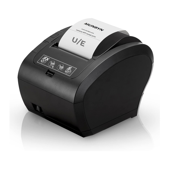
MUNBYN ITPP047 Hardware Manual
Hide thumbs
Also See for ITPP047:
- Software manual (78 pages) ,
- Easy setup manual (18 pages) ,
- Manual (15 pages)
Summary of Contents for MUNBYN ITPP047
- Page 1 ITPP047 Thermal Printer Hardware Manual 1.00 Document Name: ITPP047 Hardware Manual-1.00.docx Name Signature Date Prepared by: Byron Zhong Reviewed by: Approved by:...
-
Page 2: Version History
Version History Date Changes Version 2020-1-9 Phillip 1.00 Circuit diagram, layout Page2 of 21 ITPP047 Thermal Printer Hardware Manual Version 1.00... -
Page 3: Table Of Contents
2.3. Turning on the Power............................16 3.0. Maintenance..........................17 3.1. Periodical Cleaning............................17 3.2. Cutter Stuck Maintenance..........................18 4.0. Peripheral Unit Drive Circuit...................... 19 4.1. Peripheral Drive Connector..........................19 4.2. Drive Circuit..............................20 Page3 of 21 ITPP047 Thermal Printer Hardware Manual Version 1.00... -
Page 4: Unpacking And Installation
Note that it is a good idea to keep the original box and all the packing materials just in case you need to pack the printer up again and send it somewhere at a later date. Page4 of 21 ITPP047 Thermal Printer Hardware Manual Version 1.00... -
Page 5: Find A Proper Place For Printer
2. Never attempt to repair this product yourself. Improper repair work can be dangerous. 3. Never disassemble or modify this product. Tampering with this product may result injury, fire, or electric shock. Page5 of 21 ITPP047 Thermal Printer Hardware Manual Version 1.00... -
Page 6: Control Panel And Other Functions
Power indicator:display the connection status of the machine power Status indicator:display the printing status (blue: normal/red: error) Feed button:press to feed the receipt paper Cover open button:open the cover Power switch:turn on the printer Page6 of 21 ITPP047 Thermal Printer Hardware Manual Version 1.00... -
Page 7: Interface(Back View)
Serial port:connect the serial cable with this port. LAN port:connect the Lan cable with this port. USB port:connect the USB cable with this port. Cash drawer:connect your cash drawer with this port. Page7 of 21 ITPP047 Thermal Printer Hardware Manual Version 1.00... -
Page 8: Indicator
Figure 1- 4 Side view 1.3.3. Indicator Figure 1- 5 Indicator Page8 of 21 ITPP047 Thermal Printer Hardware Manual Version 1.00... -
Page 9: Self-Test Page
Hold on pressing the “FEED” button for about 2-3 seconds, release “FEED” button when the “ERROR” and “PAPER LED” double-blinking at the same time. c. The printer will automatically print out self-test paper including its status and configurations. Page9 of 21 ITPP047 Thermal Printer Hardware Manual Version 1.00... -
Page 10: Initialization
Hold on pressing the “FEED” button for about 20 seconds, then “ERROR LED” on until “ERROR” and “PAPER LED” double- flash again, release the “FEED” button when buzzer alarming. At this time the printer has been initialized, restoring factory settings. 1.3.6. Hexadecimal Mode Page10 of 21 ITPP047 Thermal Printer Hardware Manual Version 1.00... -
Page 11: Installation Instructions
CAUTION: Do not pull out the end of the paper diagonally, as it will cause the paper to become jammed or skewed. Figure 1- 7 Paper direction Page11 of 21 ITPP047 Thermal Printer Hardware Manual Version 1.00... - Page 12 4) Tear off the paper as shown. Auto Cutter Mode: If the printer cover is closed after turning on the power, the cutter operates automatically and the front end of the paper is cut. Page12 of 21 ITPP047 Thermal Printer Hardware Manual Version 1.00...
- Page 13 Figure 1- 9 Tearing paper Page13 of 21 ITPP047 Thermal Printer Hardware Manual Version 1.00...
-
Page 14: Installation And Setup
1. Connect the printer and router with an Ethernet cable. 2. Connect the PC and router with an Ethernet cable. 3. Network access. Network Access Connection Printer Connection Figure 2- 1 Printer connect PC 2.2. Connecting the Power Cord Page14 of 21 ITPP047 Thermal Printer Hardware Manual Version 1.00... - Page 15 Figure 2- 2 Printer connect power CAUTION If the voltage shown on the label on the bottom of your printer does not match the voltage for your area, contact your dealer immediately. Page15 of 21 ITPP047 Thermal Printer Hardware Manual Version 1.00...
-
Page 16: Turning On The Power
We recommend that you unplug the printer from the power outlet whenever you do not plan to use it for long periods. Because of this, you should locate the printer so that the power outlet it is plugged into is nearby and easy to access. Page16 of 21 ITPP047 Thermal Printer Hardware Manual Version 1.00... -
Page 17: Maintenance
4. When alcohol completely volatilized, close top cover. 5. Connect power again, print self test to check if it is clean. Wipe With Alcohol Figure 3- 1 Clean printing head Page17 of 21 ITPP047 Thermal Printer Hardware Manual Version 1.00... -
Page 18: Cutter Stuck Maintenance
Turn off the power and then restart. Method(2) Turn off the power, then turn the gear on printing head, cutter can be returned to its original position. Turn the gear Figure 3- 2 Cutter maintenance Page18 of 21 ITPP047 Thermal Printer Hardware Manual Version 1.00... -
Page 19: Peripheral Unit Drive Circuit
Driver power +24V Driver power DRD2 Driver signal 2 DRSNS Sense signal Modular Plug: Modular plug: MOLEX 90075-0007, AMP641337, or BURNDY B-66-4 Shield Wire lead Figure 4- 1 Plug Instructions Page19 of 21 ITPP047 Thermal Printer Hardware Manual Version 1.00... -
Page 20: Drive Circuit
Figure 4- 2 Circuit Diagram Reference 2SD 1866 Circuit Configuration Drive Output: 24 V, Max. 1.0 A TR1, TR2: Transistor 2SD1866 equivalent R1=10 kΩ R2=33 kΩ Figure 4- 3 Circuit Configuration Page20 of 21 ITPP047 Thermal Printer Hardware Manual Version 1.00... - Page 21 6. Absolute maximum rating for transistors TR1 and TR2 (Ta = 25°C) are: Collector current Ic = 2 A Contact Us Need technical support, contact us by: E-mail: support@munbyn.com Whatsapp: +8617817881067 Skype: munbyn Support time: Monday to Friday 24 hours. Page21 of 21 ITPP047 Thermal Printer Hardware Manual Version 1.00...


Need help?
Do you have a question about the ITPP047 and is the answer not in the manual?
Questions and answers