Eaton Digitrip RMS 810 Instructions Manual
Trip unit
Hide thumbs
Also See for Digitrip RMS 810:
- Instructions manual (79 pages) ,
- Instructional leaflet (24 pages)
Table of Contents
Advertisement
Quick Links
Advertisement
Table of Contents

Related Manuals for Eaton Digitrip RMS 810


Summary of Contents for Eaton Digitrip RMS 810
- Page 1 BCS Switchgear Inc. Switchgear | Circuit Breakers | Parts | Tech Support Effective July 2011 Instruction Leaflet I. L. 29-888B Supersedes I.L. 29-888A 5/97 Instructions for Digitrip RMS 810 Trip Unit bcsswitchgear.com | 888.599.0486 Need Help? 888.599.0486...
-
Page 2: Table Of Contents
1 .1 Basic Digitrip RMS 810 Trip Unit . . . . . . . . . . . . . . . . - Page 3 Table 1 . Digitrip RMS 810 Protection Functions . . . . . . . . . . . . . . . . .
-
Page 4: Important Safety Instructions
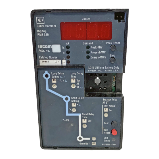
1.1 Basic Digitrip RMS 810 Trip Unit DO NOT ATTEMPT TO INSTALL OR PERFORM MAINTENANCE ON The Digitrip RMS 810, illustrated in Figure 1, is a Trip Unit suitable EQUIPMENT WHILE IT IS ENERGIZED. DEATH OR SEVERE PERSONAL for use in types DS and DSL Low-Voltage AC power circuit breakers INJURY CAN RESULT FROM CONTACT WITH ENERGIZED EQUIPMENT. -
Page 5: Operational Status And Protection Trip Indicators
(see Section 1 .4) will maintain the LED "RED" and will continue to send a TRIP signal to LOCKOUT the circuit breaker until the Trip Unit is RESET. The Digitrip RMS 810 Trip Unit can be RESET in two ways: Either press and release the "TRIP RESET"... -
Page 6: General Over-Current Protection
Section 4 .5 . grally mounted in the circuit breaker . The Digitrip RMS 810 Trip Unit is available in six different types . otee: The Digitrip RMS 810 performs all of its protection functions regardless of the status of the battery . - Page 7 Instructions for Digitrip RMS 810 Trip Unit Instruction Leaflet I. L. 29-888B Effective July 2011 Table 1. Digitrip RMS 810 Protection Functions. Trip Unit Type RMS Digitrip 810 Catalog Number Refer to I.L. Section Number Suffix Number 81 82 83 84 85 86 Instruction Leaflet No.
-
Page 8: Figure 3 . Digitrip Rms 810 Type Ll
Instructions for Digitrip RMS 810 Trip Unit Instruction Leaflet I. L. 29-888B Effective July 2011 Figure 3. Digitrip RMS 810 Type LI. Figure 5. Digitrip RMS 810 Type LSI. Figure 6. Digitrip RMS 810 Type LIG. Figure 4. Digitrip RMS 810 Type LS. -
Page 9: (For Types Ls And Lsg Trip Units Only)
1.1.3 Discriminator (High Initial Current Release) (For Types LS and LSG Trip Units Only) When the Digitrip RMS 810 Trip Unit is not equipped with an adjustable instantaneous protection setting, i .e . types LS or LSG, a DlScriminator circuit (or high initial current release) is provided . The... -
Page 10: Override (Fixed Instantaneous)
1.2.1 Values Displayed During Normal Service 1.1.4 OVERRIDE (Fixed Instantaneous) Each Digitrip RMS 810 Trip Unit has a Fixed Instantaneous "Override" The alpha-numeric display window provides informational values analog trip circuit pre-set to a value no greater than the short-time... - Page 11 Instructions for Digitrip RMS 810 Trip Unit Instruction Leaflet I. L. 29-888B Effective July 2011 Table 2. Digitrip RMS 810 Information Functions. Trip Unit Type RMS Digitrip 810 Catalog Number Refer to I.L. Section Number Suffix Number 81 82 83 84 85 86 Instruction Leaflet No.
- Page 12 Instructions for Digitrip RMS 810 Trip Unit Instruction Leaflet I. L. 29-888B Effective July 2011 Table 3. Digitrip RMS 810 Trip Unit Message Codes and their Meanings. Message Meaning comment Sec, DISC DISCriminator Trip (High initial Current Breaker tripped instantaneously because phase current exceeded 11 x rating 1.1.3...
-
Page 13: Instrumentation - Power And Energy Values
120 Vac control power is maintained to the Power / Relay Module, The Digitrip RMS 810 Trip Unit displays power and energy values . By it can be viewed . If the 120 Vac control power is lost and then is using the circuit breaker current sensors and an integrally mounted restored, the Energy value is also restored . -
Page 14: Figure 9. Rating Plug
, the basis for the Trip Unit protec- tion function current settings (see Section 3 for details) . Each circuit Rating Plugs for the Digitrip RMS 810 Trip Units are marked for, and breaker frame rating represents the maximum current it can carry may be applied on both 50 and 60 Hz systems . -
Page 15: Power / Relay Module
• COMMUNICATIONS CLOSE contact, which operates the circuit maintain the mode of trip LED indication in the Digitrip RMS 810 Trip breaker's closing release, on command from INCOM / IMPACC® Unit when external control power to the Power / Relay module is not (see Section 5 .8 .) . -
Page 16: Potential Transformer Module
Power / Relay Module (see Section 1 .4) . When a drawout circuit Disconnect breaker is equipped with a Digitrip RMS 810 Trip Unit, it can be con- Plug before veniently set and tested while the circuit breaker is either out of its... -
Page 17: Protection Settings
Instructions for Digitrip RMS 810 Trip Unit Instruction Leaflet I. L. 29-888B Effective July 2011 3 protection Settings 3.3 Long Delay Time Setting There are eight (8) available Long Delay Time Settings, as illustrated 3.1 General in Figure 14, ranging from 2 to 24 seconds . These settings are the... -
Page 18: Short Delay Time Setting
Instructions for Digitrip RMS 810 Trip Unit Instruction Leaflet I. L. 29-888B Effective July 2011 3.7 No Instantaneous Current Setting 3.5 Short Delay Time Setting For types LS and LSG Trip Units, please see Sections 1 .1 .3 As illustrated in Figure 16, there are two different Short Delay curve shapes, i .e ., fixed time (flat) and I... -
Page 19: Ground Fault Time Delay Setting
Instructions for Digitrip RMS 810 Trip Unit Instruction Leaflet I. L. 29-888B Effective July 2011 4 test procedures 3.9 Ground Fault Time Delay Setting As illustrated in Figure 19, there are two different Ground Fault 4.1 General curve shapes, i .e ., fixed time (flat) and I t response . -
Page 20: Testing Provisions
• executed by the Trip Unit. Trip Release; • Since the Digitrip RMS 810 Trip Unit is designed to run with control power from the Power / Relay Module for the display window and Trip Settings; • communications functions, all testing should be conducted with the LEDs;... -
Page 21: Not Tripping The Breaker
The battery is provided only to maintain the "RED" LED indication of make the breaker appear to trip too soon . the cause of TRIP in the Digitrip RMS 810 Trip Unit when external otee: To STOP a TEST initiated via the integral test panel PRESS AND control power to the Power / Relay Module is not available . -
Page 22: Communications
® value will return to the display window . If control power is lost, cuit breaker individually, the Digitrip RMS 810 Trip Unit has a unique the Trip Unit will still know its (new) address and baud rate . 3-digit "ADDRESS", which INCOM uses to identify the Trip Unit and ®... -
Page 23: Assemblies Electronic Monitor (Aem-Ii) And Breaker
Monitor (BIM) can be applied in the same assembly with the circuit breakers, or at a location remote from the breakers, to monitor the information from any of the Digitrip RMS 810 Trip Units . The connec- tions in the network are made by twisted pairs of wires as shown in Figure 22 . -
Page 24: Both Remote Master Computer And Aem / Bim
• 5.6 lnformation Communicated by Digitrip RMS 810 These bursts of data can be captured and used in a variety of ways The Digitrip RMS 810 Trip Unit utilizes the Eaton INCOM serialized ® depending upon the manner in which the master computer software protocol to send out coded messages . - Page 25 Instructions for Digitrip RMS 810 Trip Unit Instruction Leaflet I. L. 29-888B Effective July 2011 Refer to the IMPACC System Communications reference program- ® ming guide (see Section 6) for more information . The information available through INCOM is actually greater than that available local- ®...
-
Page 26: System Power Factor (Remote)
Effective July 2011 5.9 Remote Resetting of the Trip Unit 5.7 System Power Factor (Remote) The Digitrip RMS 810 can send the present value of the system NOTICE power factor to a remote terminal even though system power fac- tor is not available for local display in the Trip Unit window The range... -
Page 27: References
Instructions for Digitrip RMS 810 Trip Unit Instruction Leaflet I. L. 29-888B Effective July 2011 6 references 6.4 Type SPB Systems Pow-R Breakers I .L . 29-801 lnstruction for the Systems Pow-R Breaker and 6.1 Digitrip RMS Trip Assemblies Drawout Mechanism I .L . -
Page 28: Appendix A: Zone Lnterlocking
Instructions for Digitrip RMS 810 Trip Unit Instruction Leaflet I. L. 29-888B Effective July 2011 appenDiX a: Zone lnterlocking Assume a ground fault of 2000 Amperes occurs and refer to Figure 3200 A M a i n A .1 . -
Page 29: Trips
Instructions for Digitrip RMS 810 Trip Unit Instruction Leaflet I. L. 29-888B Effective July 2011 The "HILD" message would begin to flash in the window when appenDiX B: interpreting Display codes • the overload condition had exceeded 0 .85 x I... - Page 30 Instructions for Digitrip RMS 810 Trip Unit Instruction Leaflet I. L. 29-888B Effective July 2011 Notese: eaton corporation www.eaton.com...
- Page 31 Instructions for Digitrip RMS 810 Trip Unit Instruction Leaflet I. L. 29-888B Effective July 2011 Notese: eaton corporation www.eaton.com...
- Page 32 OF DEALING OR USAGE OF TRADE, ARE MADE REGARDING THE INFORMATION, RECOMMENDATIONS, AND DESCRIPTIONS CONTAINED HEREIN. In no event will Eaton be responsible to the purchaser or user in contract, in tort (including negligence), strict liability or otherwise for any special, indirect, incidental or consequential damage or loss...
Need help?
Do you have a question about the Digitrip RMS 810 and is the answer not in the manual?
Questions and answers