Table of Contents
Advertisement
Quick Links
Advertisement
Table of Contents

Related Manuals for Microsemi ZL70550


Summary of Contents for Microsemi ZL70550
- Page 1 ZL70550 Application Development Kit (ADK) User’s Guide...
-
Page 2: Table Of Contents
ZL70550 Application Development Kit (ADK) User’s Guide Table of Contents 1 Introduction .............................. 4 2 Installation and Setup ..........................5 Hardware List ..........................5 System Hardware Components ...................... 5 Jumper Configuration ........................6 Switch Configuration ........................7 Hardware and Software Installation ....................7 3 Operation .............................. - Page 3 ZL70550 Application Development Kit (ADK) User’s Guide List of Figures Figure 1 – Example Remote Unit ......................6 Figure 2 – ADK Main Form ........................9 Figure 3 – Base Unit Main Form......................11 Figure 4 – Remote Unit Main Form ......................12 Figure 5 –...
-
Page 4: Introduction
In addition to being a working system to evaluate performance of the ZL70550 device, the kit provides hardware and software design examples to aid in the development of products. -
Page 5: Installation And Setup
5. USB cable, mini-B to A — Qty 2 System Hardware Components This paragraph provides a brief description of the main hardware components of the ZL70550 ADK. Base Unit: The base unit is comprised of a BASE550 board mated to an ADP200 board. -
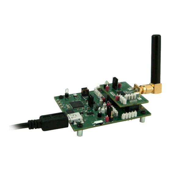
Page 6: Jumper Configuration
BASE550 and REMOTE550 When installed, provides power to the ZL70550 device. Allows the user to measure the current to the ZL70550 device by removing the jumper and placing a current meter across the jumper. -
Page 7: Switch Configuration
Installation on Windows XP is not officially supported. However, Microsemi testing showed that the software may install and operate normally on a Windows XP platform. If issues arise with customers using Windows XP, Microsemi’s recommendation is to upgrade to Windows 7 or 8. - Page 8 At that point, take the steps necessary to install the driver located in one of the following folders: − For Windows 8 and later, use C:\Program Files (x86)\Microsemi\ZL70550 ADK 1.0.X\USB Driver\Signed (for Windows 8 and newer) − For Windows 7 and earlier, use C:\Program Files (x86)\Microsemi\ZL70550 ADK 1.0.X\USB Driver\Unsigned (for Windows 7 and older)
-
Page 9: Operation
3 Operation This chapter describes in detail the operation of the main components of the ZL70550 ADK for both the base unit and the remote unit. ADK Main Form The main form for the ADK (refer to Figure 2) controls the launch of the ADK application and its components. - Page 10 ZL70550 Application Development Kit (ADK) User’s Guide • System Settings: When the ADK application is first launched, click the System Settings button to see the expanded view that includes the System Settings section and its field (as shown in Figure 2 on page 9).
-
Page 11: Base Unit And Remote Unit Main Forms
Figure 4 on page 12). The upper section contains tabs allowing access to the different configuration settings of the ZL70550, as well as providing for control of operational modes of the device (for example, test functions). The lower section is a static display that allows for basic system status and control for the main operational features of the ZL70550 (for example, link status). -
Page 12: Figure 4 - Remote Unit Main Form
ZL70550 Application Development Kit (ADK) User’s Guide Figure 4 – Remote Unit Main Form Revision 1... -
Page 13: System Status And Control
Refer to the ZL70550 Programmer User's Guide for synthesizer frequency calculations. − VCO Band: Since the ZL70550 VCO can be used over a wide range of frequencies, it is split into sixteen bands of operation. The VCO Range field displays the VCO band. -
Page 14: Zl70550 Setup Display Tab
System Status and Control section. Figure 5 – ZL70550 Setup Display Tab The ZL70550 Setup tab contains one section, Radio Setup, which in turn contains one subsection, Frequency Setup. Frequency Setup has the following fields: −... -
Page 15: Cca & Cal Display Tab
ZL70550 Application Development Kit (ADK) User’s Guide − SAW Filters (base unit only): This group of radio buttons allows the user to select an appropriate SAW filter for the band of operation in which the user is working. For example, if the user is testing in the US ISM band, they may want to select the SAW filter for this band to attenuate out-of-band emissions. - Page 16 W button. The user can read the value for a trim register by pressing the R button for the trim register of interest. Values are in decimal format. Refer to the ZL70550 Programmer User’s Guide for a description of the calibrations. •...
-
Page 17: Test Display Tab
Figure 7) allows users to perform certain test functions with the ZL70550, such as transmitting a carrier wave or performing a PER test. Figure 7 – Test Display Tab The Test display tab contains four subsections, one for PER testing, one for TX carrier wave testing, one for RX testing, and one for manually sending a radio command. - Page 18 ZL70550 Application Development Kit (ADK) User’s Guide Note: Before running a PER test, be sure to set the following to the desired settings: - The LNA gain on the BASE550 board using a combination of the lna_bias_trim[3:0] on the CCA & Cal tab and the LNA Setting on the Test tab.
- Page 19 TX carrier test function for the ZL70550 output. − TX Pwr Setting: This field provides the register setting in decimal for the TX output power of the ZL70550 It may be read from or written to by pressing the R (read) or W (write) button, respectively. −...
-
Page 20: Registers Main Form
ZL70550 Application Development Kit (ADK) User’s Guide Registers Main Form The registers main form for the ADK provides access to all ZL70550 registers. Similar to the main forms for the base unit and remote unit, the registers main form uses tabs to access the various groups of ZL70550 registers. -
Page 21: Figure 9 - Sample Register Access Subsection
R: Pressing the R button causes a read from the register of the ZL70550 at the address displayed in the register name, and displays the register’s value in both the byte- and bit-level access fields. -
Page 22: Register Controls Section
The buttons and fields in this section are: • Write All: When this button is pressed, all outstanding register changes (shown in red on the register tabs) are written to the ZL70550. This operation takes a few seconds to complete. •... -
Page 23: Figure 10 - Register Settings Saved To Text File
ZL70550 Application Development Kit (ADK) User’s Guide Figure 10 – Register Settings Saved to Text File Figure 11 – Register Name Search Result Revision 1... -
Page 24: Register Description Window
ZL70550 Application Development Kit (ADK) User’s Guide 3.3.3 Register Description Window The Register Description window is displayed when a user double-clicks on a register name (near the address) in the register tabs. Figure 12 shows an example of the Register Description window for the DP_CTRL0 register. -
Page 25: Getting Started Guide
"3.1 ADK Main Form" on page 9). 5. Launch the base unit main form and the remote unit main form from the ZL70550 Application Development Kit (ADK) main form. 6. Make sure that no error messages are displayed in the GUI for either unit. (Error... -
Page 26: A Performing Firmware Updates
This appendix describes how to program the firmware on the boards included with the ZL70550 Application Development Kit. The ADK is shipped with the latest firmware installed. If customers want to either modify the software for their own needs or install firmware updates from a future release, follow the procedure outlined in this appendix. -
Page 27: B References
B References Document Document Title 153552 ZL70550 Programmer User’s Guide 152078 ZL70550 Datasheet 154566 ZL70550 ADK Release Notes ZL70550 ADK Source Code Overview Revision 1... -
Page 28: C Glossary
ADP200 board, which represents a typical remote device application. ZL70550 ZL70550 Application Development Kit. A combination of hardware and software components that make up a complete test and evaluation system based on Microsemi's ZL70550 Ultra-Low-Power Sub-GHz RF Transceiver. - Page 29 ZL70550 Application Development Kit (ADK) User’s Guide Term Definition Universal serial bus Voltage-controlled oscillator Zone information protocol (a protocol that allows compression of files) or the three-character file extension on such a compressed file Revision 1...
-
Page 30: D List Of Changes
D List of Changes The following table lists substantive changes that were made in the ZL70550 Application Development Kit (ADK) User’s Guide. Revision Change Page Revision 1 Initial revision for ZL70550 ADK release 1.0.0. – (March 2016) Revision 1... -
Page 31: E Product Support
Via e-mail, write to sales.support@microsemi.com E.2 Website For more information, please visit www.microsemi.com, where you can browse a variety of technical and nontechnical information. Many answers available on the searchable web resource include diagrams, illustrations, and links to other resources on the website. - Page 32 Information provided in this document is proprietary to Microsemi, trademarks and service marks are the property of their and Microsemi reserves the right to make any changes to the information in this document or to any respective owners.
Need help?
Do you have a question about the ZL70550 and is the answer not in the manual?
Questions and answers