Table of Contents
Advertisement
Quick Links
Advertisement
Table of Contents

Related Manuals for Microsemi IGLOO nano Starter Kit


Summary of Contents for Microsemi IGLOO nano Starter Kit
- Page 1 IGLOO nano Starter Kit User’s Guide...
-
Page 2: Table Of Contents
IGLOO nano Starter Kit Description ........ -
Page 3: Introduction
Flash*Freeze modes) with the core operating at either 1.2 V or 1.5 V. When using the board in conjunction with Microsemi’s power analysis tools, you will have a clear picture of application power consumption at each stage in your design. -
Page 4: Kit Contents
USB 2.0 high-speed cables Quickstart card Web-Based Resources Listed below are the documents currently published on the Microsemi SoC Products Group website. Additional documents and design examples may be added to the website in the future. Users Guides and Tutorials IGLOO nano Starter Kit User’s Guide... - Page 5 IGLOO Icicle Verilog Design Files www.microsemi.com/soc/documents/IGLOO_Icicle_tutorial_verilog_Libero84sp2_revA.zip IGLOO Icicle VHDL Design Files www.microsemi.com/soc/documents/IGLOO_Icicle_tutorial_VHDL_Libero84sp2_revA.zip Board References IGLOO nano Starter Kit Board – Allegro PCB file www.microsemi.com/soc/documents/IGLOO_nano_StarterKit_PCB.zip IGLOO nano Starter Kit Board – OrCAD Schematics (DSN) www.microsemi.com/soc/documents/IGLOO_nano_StarterKit_DSN.zip IGLOO nano Starter Kit Board – PDF Schematics www.microsemi.com/soc/documents/IGLOO_nano_StarterKit_SS.pdf...
-
Page 7: Board Components And Settings
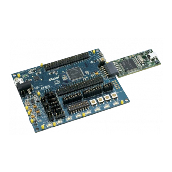
1 – Board Components and Settings This chapter describes the components and settings for the IGLOO nano Evaluation Board. Block Diagram The IGLOO nano board Evaluation Board is shown in Figure 1-1. Figure 1-1 • IGLOO nano Evaluation Board R e v i s i o n 3... -
Page 8: Igloo Nano Board Stackup
Board Components and Settings IGLOO nano Board Stackup The IGLOO nano board is built on a four-layer printed circuit board (PCB): 1. Top Signal (Figure 1-2) 2. Power 3. GND 4. Bottom Signal (Figure 1-3 on page Figure 1-2 • Top Silkscreen R e vi s i o n 3... - Page 9 IGLOO nano Starter Kit Figure 1-3 • Bottom Silkscreen R e v i s i o n 3...
-
Page 10: Jumper And Switch Settings
Board Components and Settings Jumper and Switch Settings Recommended default jumper settings are defined in Table 1-1. The voltage selection jumpers are highlighted in grey. Connect jumpers in the default settings described in Table 1-1 to enable the pre- programmed demo design to function correctly. Table 1-1 •... -
Page 11: Fpga Description: Agln250V2-Vqg100
IGLOO nano Starter Kit FPGA Description: AGLN250V2-VQG100 This IGLOO nano board is populated with an IGLOO nano AGLN250V2-VQG100 FPGA. An IGLOO nano AGLN250 FPGA supports the enhanced nano features of Schmitt Trigger input, bus hold (holds previous I/O state in Flash*Freeze mode), cold-sparing, hot-swap I/O capability, and 1.2 V programming. - Page 12 Board Components and Settings AGLN250V2-VQG100 I/O Banks and Pins Figure 1-4 shows the I/O banks for AGLN250V2-VQG100. IO BANK0 IO BANK0 agl_b0_p98 agl_b0_p85 [8] GAA0/IO00RSB0 IO10RSB0 agl_b0_p97 agl_b0_p84 [8] GAA1/IO01RSB0 IO11RSB0 agl_b0_p96 agl_b0_p83 [8] GAB0/IO02RSB0 IO12RSB0 agl_b0_p95 agl_b0_p82 [8] GAB1/IO03RSB0 IO13RSB0 agl_b0_p94 agl_b0_p81 [8]...
- Page 13 IGLOO nano Starter Kit This FPGA has advanced I/O features such as JTAG pins for the IEEE 1149.1 JTAG Boundary Scan Test (Figure 1-5). JTAG & Special JTAG & Special 39R-0603 39R-0603 agl_tdi agl_tdo [5] agl_tck agl_tms [5] [2,5] agl_trst...
-
Page 15: Power
2 – Power The IGLOO nano development board is powered through an external voltage power brick or USB. If both the power brick and USB are plugged in, the development board will power through the power brick. If the power brick is unplugged, the board will seamlessly switch to power through the USB. In the USB option, in-rush current meets USB specifications. -
Page 16: Battery
Power Table 2-2 gives a summary of the power modes available with IGLOO nano devices in general and is extracted from the “Flash*Freeze Technology and Low Power Modes” chapter of the IGLOO nano FPGA Fabric User’s Guide. Table 2-2 • Power Modes ULSICC To Resume Mode... -
Page 17: Current Measurement
IGLOO nano Starter Kit Current Measurement Once the IGLOO nano evaluation board is powered up, you can evaluate power usage by current consumption, using the current measurement pins on the board. All banks are separated and two of the banks have the option of powering through 3.3 V or 2.5 V. - Page 18 Power Figure 2-4 shows the schematic for the current measurement headers. Note: Short Pins 1-2: +3.3V Short Pins 3-4: +2.5V Short Pins 5-6: VCC_CORE (+1.5V/+1.2V) 4x1 Header (M) 4x1 Header (M) 4x1 Header (M) 4x1 Header (M) VCC_CORE VCC_2_5 VCC_3_3 VCC_B0 VCC_3_3 VCC_B2...
-
Page 19: Operation Of Board Components
Rise and Fall Time (0.2 VDD and 0.8 VDD) 10 ns (maximum) Start-up Time 10 ms (maximum) Reference Additional information on this clock oscillator is available at the IGLOO nano Starter Kit website: www.microsemi.com/soc/products/hardware/devkits_boards/igloonano_starter.aspx. Schematic Figure 3-1 shows the schematic for the clock oscillator. -
Page 20: Reset
150 ms to allow the power supply and processor to stabilize. Reference Additional information on this push-button reset switch is available at the IGLOO nano Starter Kit website: www.microsemi.com/soc/products/hardware/devkits_boards/igloonano_starter.aspx. -
Page 21: Flash*Freeze Switch
IGLOO nano Starter Kit Flash*Freeze Switch Flash*Freeze technology enables the user to quickly (within 1 µs) enter and exit Flash*Freeze mode by activating the Flash*Freeze pin while all power supplies are kept at their original values. I/Os, global I/Os, and clocks can still be driven and can be toggling without impact on power consumption, and the device retains all core registers, SRAM information, and I/O states. -
Page 22: Push-Button Switches
Operation of Board Components Push-Button Switches Four active low push-button switches are provided on the board for user debug. You can remove the corresponding jumpers from the 4 x 2 Header to detach any of the four push-button switches from the FPGA I/O. -
Page 23: Dip Switches
IGLOO nano Starter Kit DIP Switches A DIP switch pack (8 switches) is provided on the board. You can remove the corresponding jumpers from the 8 x 2 header to detach any of the eight DIP Switches from the FPGA I/O. -
Page 24: User Leds
Operation of Board Components User LEDs Eight active low debug LEDs are provided on the board. You can remove the corresponding jumpers from the 8 x 2 headers to detach any of the eight LEDs from the FPGA I/O. VCC_3_3 LED1 LED1 RED SMD LED - 1206... - Page 25 IGLOO nano Starter Kit DIP switches, and push-button switches, you must first remove the corresponding 2-pin jumper on their path. IO_B0 IO_B1 100 mils × N IGLOO (N = 1, 2, 3, 4, ...) IO_B2 IO_B3 Figure 3-11 • I/O Test Pins...
-
Page 26: Usb-To-Uart Interface
IGLOO nano FPGA. Any standard UART controller can be implemented in the IGLOO nano FPGA to allow access with this interface. In addition, the Microsemi IP catalog includes various UART controllers, specifically CoreUART, which can be instantiated in the FPGA design with an embedded processor. -
Page 27: Low-Cost Programming Stick (Lcps)
IGLOO AGLN250V2-VQG100. Note: The LCPS supplied with this kit is intended for use with the IGLOO nano Starter Kit. An LCPS supplied for another kit, although electrically and functionally equivalent, may not connect seamlessly with the IGLOO nano Starter Kit board. -
Page 29: Programming
4 – Programming To program a design into the IGLOO nano evaluation board: 1. Attach the LCPS board to the IGLOO nano evaluation board. 2. Attach a USB cable to the LCPS. This allows a programming data file, in programming database format (*.pdb) or STAPL format (*.stp), to be downloaded via the FlashPro software to the IGLOO nano device fitted to the board. -
Page 31: Board Demonstration
You can easily use this demo as a guide to create your own design for evaluation. The demo design RTL code and design files are available at the IGLOO nano Starter Kit website: www.microsemi.com/soc/products/hardware/devkits_boards/igloonano_starter.aspx Powering Up the Board and Running the Demo 1. -
Page 33: A Resources
A – Resources IGLOO nano Starter Kit www.microsemi.com/soc/products/hardware/devkits_boards/igloonano_starter.aspx IGLOO nano Overview www.microsemi.com/soc/products/igloonano/default.aspx IGLOO nano Datasheet www.microsemi.com/soc/documents/IGLOO_nano_DS.pdf IGLOO nano FPGA Fabric User’s Guide www.microsemi.com/soc/documents/IGLOO_nano_UG.pdf Microsemi FPGA and SoC Development Software www.microsemi.com/soc/products/software/libero/default.aspx R e v i s i o n 3... -
Page 35: B List Of Changes
Page Revision 3 The document format and website references were changed from Actel to (January 2013) Microsemi; Actel is now Microsemi SoC Products Group. The "Product Support" information was updated. Libero Integrated Design Environment (IDE) was updated to Libero System-on-Chip Multi (SoC) software. -
Page 37: C Product Support
Microsemi SoC Products Group staffs its Customer Technical Support Center with highly skilled engineers who can help answer your hardware, software, and design questions about Microsemi SoC Products. The Customer Technical Support Center spends a great deal of time creating application notes, answers to common design cycle questions, documentation of known issues, and various FAQs. -
Page 38: Itar Technical Support
For technical support on RH and RT FPGAs that are regulated by International Traffic in Arms Regulations (ITAR), contact us via soc_tech_itar@microsemi.com. Alternatively, within Cases, select Yes in the ITAR drop-down list. For a complete list of ITAR-regulated Microsemi FPGAs, visit the ITAR web page. -
Page 39: Index
37 stackup 8 top silkscreen 8 product support customer service 37 clock oscillator specifications email 37 contacting Microsemi SoC Products Group My Cases 38 customer service 37 outside the U.S. 38 email 37 technical support 37 web-based technical support 37... - Page 40 Index tech support USB-to-UART ITAR 38 interface 4 My Cases 38 User LEDs outside the U.S. 38 technical support web-based technical support R e visio n 3...
- Page 42 Microsemi Corporate Headquarters One Enterprise, Aliso Viejo CA 92656 USA © 2013 Microsemi Corporation. All rights reserved. Microsemi and the Microsemi logo are trademarks of Within the USA: +1 (949) 380-6100 Microsemi Corporation. All other trademarks and service marks are the property of their respective owners.
Need help?
Do you have a question about the IGLOO nano Starter Kit and is the answer not in the manual?
Questions and answers