Table of Contents
Advertisement
Available languages
Available languages
Quick Links
Advertisement
Table of Contents

Subscribe to Our Youtube Channel
Related Manuals for Chauvet Professional PVP S5


Summary of Contents for Chauvet Professional PVP S5
- Page 1 Series User Manual...
- Page 2 Edition Notes Edition Notes This User Manual covers the description, safety precautions, setup, installation, operation, and maintenance for all Precision Video Panels offered by Chauvet. This edition was published in March 2015. CHAUVET® is a registered trademark of CHAUVET & Sons LLC. (d/b/a CHAUVET® or Trademarks Chauvet).
-
Page 3: Table Of Contents
Table of Contents Table of Contents 1. Before You Begin ............................1 What Is Included ................................1 Unpacking Instructions ..............................1 Claims ......................................1 Manual Conventions ..................................1 Symbols ......................................1 Safety Notes ..................................2 Expected LED Lifespan ..............................2 2. - Page 4 Table of Contents VIP™ Sample Video Wall System Setup .......................... 20 8. Operation ..............................21 Additional Hardware and Software ............................ 21 About CHAUVET® LED Studio ............................22 Description ..................................... 22 9. Technical Information ..........................22 PVP™ Maintenance ................................22 Troubleshooting Guide ..............................23 Returns ....................................
- Page 5 Table of Contents 1. Antes de empezar ............................- 26 - Qué va incluido .................................. - 26 - Instrucciones de desembalaje ............................- 26 - Reclamaciones....................................- 26 - Convenciones del manual ................................- 26 - Símbolos ......................................- 26 - Notas de seguridad ................................
- Page 6 Table of Contents Hardware y software adicional ............................- 46 - Acerca de CHAUVET® LED Studio ..........................- 47 - Descripción ....................................- 47 - 9. Información técnica ............................ - 47 - Mantenimiento del PVP™ ..............................- 47 - Guía de resolución de problemas ............................. - 48 - Devoluciones ..................................
- Page 7 Table of Contents 1. Avant de commencer ..........................51 Contenu ..................................... 51 Instructions de déballage ..............................51 Réclamations ....................................51 Conventions manuelles .................................. 51 Symboles ....................................... 51 Consignes de Sécurité ..............................52 Durée de vie des LEDs ..............................52 2. Introduction ..............................53 Description de l'appareil ..............................
- Page 8 Table of Contents Matériel et logiciel additionnels ............................72 A propos de CHAUVET® LED Studio ..........................73 Description ..................................... 73 9. Informations Techniques ..........................73 Entretien du PVP™ ................................73 Guide de dépannage ................................. 74 Renvois ....................................74 10. Spécifications techniques ........................75 viii- PVP™...
- Page 9 Table of Contents 1. Voordat u begint ............................77 Wat is er inbegrepen ................................. 77 Uitpakinstructies ................................77 Claims ......................................77 Conventies van deze handleiding ..............................77 Symbolen ....................................... 77 Veiligheidsinstructies ................................. 78 Verwachte levensduur van de LED-lamp .......................... 78 2.
- Page 10 Table of Contents Extra apparatuur en software ............................98 Over CHAUVET® LED Studio ............................99 Beschrijving ....................................99 9. Technische informatie ..........................99 Onderhoud van de PVP™ ..............................99 Gids voor probleemoplossing ............................100 Retouren .................................... 100 10. Technische Specificaties .......................... 101 Contact Us ...............................
-
Page 11: Before You Begin
Before You Begin 1. Before You Begin What Is Included · 2 or 8 PVP™ (Precision Video Panels) models S5 or S7 · Neutrik® powerCON® Power input cable 6 ft (1.83 m) Included with 8-pack only · Neutrik® etherCON® Signal Cables 2.46 ft (0.75 m) 2 or 8 cables based on the number of PVPs included ·... -
Page 12: Safety Notes
Before You Begin Safety Notes Please read the following Safety Notes carefully before starting to work with the product. These notes provide important safety information about the installation, usage, and maintenance. This product contains no user-serviceable parts. Any reference to servicing in this User Manual will only apply to properly trained Chauvet certified technicians. -
Page 13: Introduction
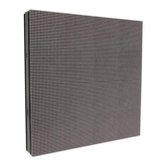
Before You Begin 2. Introduction Product The PVP™ is a Precision Video Panel. The PVP™ series is part of the VIP™ line of video wall products and includes 2 models: Description · PVP™ S5 · PVP™ S7 Each model is a video panel consisting of multiple SMD3528 tri-color LEDs. The number in each model name indicates the pixel pitch (distance, in millimeters, between the LEDs) of that model. -
Page 14: Product Overview: Pvp™ S5 And Pvp™ S7
Before You Begin Product Overview: PVP™ S5 and PVP™ S7 Signal In/Out Service Access Power In Threaded Speego Male Connection Latch Mounting Hole Size M10 (4x) Power Indicator LED Signal In/Out Power Out Test Button Signal LED Speego Female connection PVP™... - Page 15 Before You Begin The difference between each PVP™ model is the pixel pitch (space) between the LEDs and the number of pixels (LEDs) in each row and column. The basic housing and components are identical. Refer to the previous PVP™ illustration. Warning: Service Access Latch is for use by Chauvet authorized technicians only! Opening this will void the Chauvet warranty.
-
Page 16: Product Dimensions
Before You Begin Product Dimensions Each PVP™ model in the series has the same outside housing dimensions. 2.5 in 19.7 in (63 mm) (500 mm) 19.7 in (500 mm) PVP™ Pixels Per Although each PVP™ has the same outer dimensions, the LED pixels per panel vary. Each pixel is 1 SMD3528 tri-color LED. -
Page 17: Setup
Setup 3. Setup AC Power Each PVP™ has an auto-ranging power supply that works with an input voltage range of 100–240 VAC, 50/60 Hz. To determine the power requirements for each PVP™ in the series, refer to the label affixed to the product. You can also refer to the Technical Specifications chart in this manual. -
Page 18: Mounting
Mounting 4. Mounting Orientation Each PVP™ is constructed of aluminum alloy and stainless steel. This ensures each panel is stable and easy to install. Each panel also has a convenient built-in handle located on the top, underside of the panel. This handle enables you to easily pick up and securely hold each panel while mounting and working with the panels. -
Page 19: Truss Installation
Setup Truss Installation Refer to the following diagram for truss installation. Chauvet offers the PVP™ Rig Kit (sold separately) specifically designed for hanging the panels. Rig Kit (sold separately) PVP™ Series User Manual, Rev. 4... -
Page 20: Rb-S50Cm Rig Bar (Sold Separately)
Mounting RB-S50CM Rig Bar 23.15 in (Sold Separately) 1.73 in (588 mm) 1.73 in (44 mm) (44 mm) 19.69 in (500 mm) 18.50 in (470 mm) 12.60 in (320 mm) Safety Button 6.46 in (164 mm) Set-Pin 3.54 in (90 mm) 5.12 in Cotter-pin (130 mm) -
Page 21: Joining Each Pvp™ (Creating A Modular Design)
Joining Each PVP™ (Creating a Modular Design) 5. Joining Each PVP™ (Creating a Modular Design) PVPs are joined together to create a modular designed video wall. Because the panels are interchangeable, you can create a video wall by joining several of the same model or joining different models to create a larger or more complex video wall. -
Page 22: Important Notice
Twist tight to secure panel Important Notice Chauvet Professional has redesigned the speego connectors for all PVP panels starting in 2014. When assembling the PVP panels with these new speego connectors, you are able to use a crescent wrench to achieve proper alignment. -
Page 23: Horizontally Joining Panels
Joining Each PVP™ (Creating a Modular Design) Horizontally Joining Each PVP™ can be easily joined horizontally using the 2 horizontal locking knobs on the inside, left-hand top and bottom of each panel. Panels Clamps may be installed as shown below when 2 or more columns are installed. Use the following instructions to join panels horizontally: 1. -
Page 24: Connecting (Cabling) Each Pvp
Connecting (Cabling) Each PVP™ 6. Connecting (Cabling) Each PVP™ Testing Signal and Each PVP™ has 2 power sockets and 2 signal sockets. · The Power IN and Signal sockets are located on the upper right-hand corner of each Power Connections panel. -
Page 25: Connecting The Signal Input
Connecting (Cabling) Each PVP™ Connecting the The VIP™ video wall system uses 2 basic setup configurations to connect the signal to the video wall: Signal Input 1. A configuration using 24 or less panels. 2. A configuration using more than 24 panels. The next section, Connecting Power and Signal Cables, gives information on connecting... -
Page 26: Connecting Power And Signal Cables
Connecting (Cabling) Each PVP™ Connecting Power The following sections provide information and diagrams on connecting signal and power between panels. and Signal Cables Refer to the Introduction Operation sections in this User Manual for available cables and item numbers. Signal cable panel connections can use several different configurations. The basic Connecting configuration to connect the signal from one panel to the next is as follows. - Page 27 Connecting (Cabling) Each PVP™ The following diagram shows an example of a signal connection configuration using more than 24 panels. A video wall design with more than 24 panels requires: · Incoming signal connection to the VIP™ Driver. · VIP™ Driver connection to the VIP™ Signal Distributor. ·...
-
Page 28: Connecting The Power Between Joined Panels
Connecting (Cabling) Each PVP™ Power cable panel connections can also use different configurations. The basic Connecting configuration to connect the main power supply from one panel to the next is: the Power Between · The main power is connected to the first panel’s Power Input or Output. Joined Panels ·... -
Page 29: Typical Pvp™ Installation
Typical PVP™ Installation 7. Typical PVP™ Installation Because a video wall system can include different components to provide a simple to complex modular wall design, use the following steps as a general guide to get started. Step 1 Open and examine the PVP™ flight case to make sure you have received all products and accessories and that each one is in good condition. -
Page 30: Vip™ Sample Video Wall System Setup
Typical PVP™ Installation VIP™ Sample Video The following diagram provides a sample setup for a CHAUVET® VIP™ video wall system. This system setup includes an optional signal processor for additional video Wall System Setup sources, and the VIP™ Signal Distributor to support more than 24 panels. Note that the two-driver setup shown here allows for simultaneous playback of pre-recorded and live content, all directed from a single PC. -
Page 31: Operation
Operation 8. Operation Additional In addition to the panels, you will need other hardware and software to design, build, and operate your VIP™ video wall system. The following table summarizes these additional Hardware and items—some are required and others are optional. Software Item Description... -
Page 32: About Chauvet® Led Studio
Operation About CHAUVET® CHAUVET® LED Studio is a powerful and easy-to-learn software application used to design and run the VIP™ video wall system. The following is some introductory LED Studio information about this software. Refer to the CHAUVET® LED Studio User Manual for detailed information and instructions on setting up and using CHAUVET®... -
Page 33: Troubleshooting Guide
Operation Troubleshooting Guide Symptom Cause(s) Action(s) All LEDs are blinking Contact failure Fix the loose LEDs or try re-plugging LEDs on a specific circuit are not Power input cable may be connected Remove and connect correctly lit/working incorrectly Input cables connected incorrectly Find the incorrectly connected cables All LEDs do not light and reconnect properly... -
Page 34: Technical Specifications
Technical Information 10. Technical Specifications PVP™ S5 PVP™ S7 Light Source Tri-color SMD3528 LED Tri-color SMD3528 LED Pixels per Panel 96 x 96 (9,216 total) 64 x 64 (4,096 total) Pixel Pitch (between LEDs) 5.2 mm 7.8 mm Pixel Density 36,864/m 16,384/m Display Refresh Rate... - Page 35 Antes de empezar Notas de la edición Este Manual de usuario se ocupa de la descripción, precauciones de seguridad, configuración, instalación, funcionamiento y mantenimiento de todos los panes de vídeo de precisión de la oferta de Chauvet. Esta edición se publicó en abril de 2015. CHAUVET®...
-
Page 36: Antes De Empezar
Notas de la seguridad 1. Antes de empezar Qué va incluido · 2 u 8 PVP™ (paneles de vídeo de precisión), modelo S5 o S7 · Cable de entrada de alimentación Neutrik® powerCON® de 6 ft (1,83 m) Incluido con pack de 8 solamente ·... -
Page 37: Notas De Seguridad
Antes de empezar Notas de seguridad Por favor, lea las siguientes Notas de seguridad con atención antes de empezar a trabajar con el producto. Estas notas incluyen información de seguridad importante sobre la instalación, uso y mantenimiento. Este producto no contiene piezas reparables por el usuario. Cualquier referencia a la reparación en este Manual de usuario se aplicará... -
Page 38: Introducción
Notas de la seguridad 2. Introducción Descripción del El PVP™ es un panal de vídeo de precisión. La serie PVP™ forma parte de la línea VIP™ de productos de mural de vídeo y consta de 2 modelos: producto · PVP™ S5 ·... -
Page 39: Vista General Del Producto: Pvp™ S5 Y Pvp™ S7
Introducción Vista general del producto: PVP™ S5 y PVP™ S7 Entrada/Salida Entrada de Cierre de acceso de señal alimentación Agujero de Conexión macho speego de servicio montaje a rosca Tamaño M10 (4x) LED indicador de alimentación Entrada/Salida Salida de Botón de prueba LED de señal de señal alimentación... - Page 40 Notas de la seguridad La diferencia entre cada modelo PVP™ es el tamaño de píxel (espacio) entre los LED y el número de píxeles (LED) en cada fila y columna. Los componentes y carcasa básicos son idénticos. Consulte la ilustración del PVP™ anterior. Advertencia: ¡El cierre del acceso de servicio es solamente para técnicos autorizados por Chauvet! Si lo abre, quedará...
-
Page 41: Dimensiones Del Producto
Introducción Dimensiones del producto Cada modelo PVP™ de la serie tiene las mismas dimensiones exteriores de carcasa. 2.5 in 19.7 in (63 mm) (500 mm) 19.7 in (500 mm) Píxeles por panel Aunque cada PVP™ tiene las mismas dimensiones exteriores, los píxeles por panel del LED varían. -
Page 42: Instalación
Notas de la seguridad 3. Instalación Corriente alterna Todos los PVP™ tienen una fuente de alimentación con detección automática (auto- rango) que funciona con un rango de tensión de entrada de 100–240 VCA, 50/60 Hz. Para determinar los requisitos de alimentación de cada PVP™ de la serie, consulte la etiqueta fijada en el producto. -
Page 43: Montaje
Instalación 4. Montaje Orientación Todos los PVP™ están fabricados en aleación de aluminio y acero inoxidable. Esto garantiza que cada panel es estable y fácil de instalar. Cada panel lleva integrada también una cómoda asa situada en la parte superior, bajo el panel. Esta asa le posibilita agarrar fácilmente y sujetar con seguridad cada panel mientras trabaja con los paneles y los monta. -
Page 44: Kit De Aparejamiento (Vendido Por Separado)
Montaje Instalación de truss Consulte el diagrama siguiente para la instalación de truss. Chauvet dispone del Kit de aparejamiento PVP™ (vendido por separado), específicamente diseñado para colgar los paneles. Kit de aparejamiento (vendido por separado) Manual de usuario de la Serie PVP™, Rev. 4 - 34 -... -
Page 45: Rb-S50Cm Kit De Aparejamiento (Vendido Por Separado)
Instalación RB-S50CM Kit de 23,15 in (588 mm) 1,73 in aparejamiento 1,73 in (44 mm) (44 mm) 19,69 in (Vendido por (500 mm) separado) 18,50 in (470 mm) 12,60 in (320 mm) Botón de Seguridad 6,46 in (164 mm) Set-Pin 3,54 in (90 mm) 5,12 in... -
Page 46: Vertically Joining The Panels
Unir los PVP™ (crear un diseño modular) 5. Unir los PVP™ (crear un diseño modular) PVPs are joined together to create a modular designed video wall. Because the panels are interchangeable, you can create a video wall by joining several of the same model or joining different models to create a larger or more complex video wall. -
Page 47: Aviso Importante
Gire apretando fuerte para asegurar el panel Aviso importante Chauvet Professional ha rediseñado los conectores speego para todos los paneles PVP a partir de 2014. Cuando ensamble los paneles PVP con estos nuevos paneles speego, podrá usar una llave inglesa para conseguir un alineamiento correcto. -
Page 48: Unir Los Paneles Horizontalmente
Unir los PVP™ (crear un diseño modular) Unir los paneles Cada PVP™ se puede unir fácilmente en horizontal usando los 2 mandos de bloqueo horizontal en la parte interior, superior izquierda e inferior de cada panel. horizontalmente Los soportes se pueden instalar como se muestra más abajo cuando se instalan 2 o más columnas. -
Page 49: Conectar (Cablear) Los Pvp
Conectar (cablear) los PVP™ 6. Conectar (cablear) los PVP™ Probar la señal y las Cada PVP™ tiene 2 tomas de alimentación y 2 tomas de señal. · Las tomas de señal y alimentación de ENTRADA se encuentran en la esquina conexiones de superior derecha de cada panel. -
Page 50: Conectar La Entrada De Señal
Conectar (cablear) los PVP™ Conectar la entrada El sistema de mural de vídeo VIP™ utiliza 2 configuraciones básicas para conectar la señal al mural de vídeo: de señal 1. Una configuración que utiliza 24 paneles o menos. 2. Una configuración que utiliza más de 24 paneles. En el siguiente apartado, Conectar los cables de alimentación y de señal, se... -
Page 51: Conectar Los Cables De Alimentación Y Señal
Conectar (cablear) los PVP™ Conectar los cables Los siguientes apartados proporcionan información y diagramas sobre la conexión de señal y alimentación entre paneles. de alimentación y Consulte los apartados Introducción Funcionamiento de este Manual de usuario para ver los cables disponibles y los números de artículo. señal Conectar Las conexiones entre paneles del cable de señal puede usar distintas configuraciones. - Page 52 Conectar (cablear) los PVP™ El siguiente diagrama muestra un ejemplo de configuración de conexión de señal utilizando más de 24 paneles. Un diseño de mural de vídeo con más de 24 paneles necesita: · Conexión de señal entrante al VIP™ Driver. ·...
-
Page 53: Conectar La Alimentación Entre Paneles Unidos
Conectar (cablear) los PVP™ Las conexiones de alimentación entre paneles pueden usar también distintas Conectar configuraciones. La configuración básica para conectar la fuente de alimentación la alimentación entre principal de un panel a otro es: paneles unidos · La alimentación principal se conecta a la entrada o salida de alimentación del primer panel. -
Page 54: Instalación Típica Del Pvp
Instalación típica de PVP™ 7. Instalación típica del PVP™ Puesto que un sistema de mural de vídeo puede estar formado por distintos componentes para conseguir un diseño modular de simple a complejo, siga los pasos siguientes como regla general para empezar. Paso 1 Abra y examine el flight case del PVP™... -
Page 55: Configuración De Muestra De Sistema De Mural De Vídeo Vip
Instalación típica de PVP™ Configuración de El siguiente diagrama proporciona una configuración de muestra para un sistema de mural de vídeo CHAUVET® VIP™. La instalación del sistema incluye un procesador de muestra de sistema señal opcional para fuentes de vídeo adicionales, y el distribuidor de señal VIP™ para que admita más de 24 paneles. -
Page 56: Funcionamiento
Funcionamiento 8. Funcionamiento Hardware y Además de los paneles, se necesita otro software y hardware para diseñar, construir y manejar su sistema de mural de vídeo VIP™. La siguiente tabla resume estos software adicional elementos adicionales. Algunos son necesarios y otros opcionales. Elemento Descripción Código de... -
Page 57: Acerca De Chauvet® Led Studio
Funcionamiento Acerca de CHAUVET® LED Studio es una aplicación de software potente y de fácil aprendizaje que se utiliza para diseñar y administrar el sistema de mural de vídeo VIP™. A CHAUVET® LED continuación proporcionamos una información a modo de introducción sobre el software. Consulte el Manual de usuario de CHAUVET®... -
Page 58: Guía De Resolución De Problemas
Información técnica Guía de resolución de problemas Síntoma Causa(s) Acciones Fallo de contacto Arregle los LED flojos o intente volver a Todos LED están parpadeando conectar Puede que el cable de entrada de Los LED de un circuito concreto no alimentación no esté... -
Page 59: Especificaciones Técnicas
Especificaciones técnicas 10. Especificaciones técnicas PVP™ S5 PVP™ S7 Fuente de luz LED tricolor SMD3528 LED tricolor SMD3528 Píxeles por panel 96 x 96 (9.216 total) 64 x 64 (4.096 total) Tamaño de píxel (entre LED) 5,2 mm 7,8 mm Densidad de píxel 36.864/m 16.384/m... - Page 60 Notes d'édition Notes d'édition Ce manuel d'utilisation comporte la description, les mesures de précautions, la configuration, l'installation, l'utilisation et la maintenance pour tous les panneaux vidéo Precision proposés par Chauvet. Cette édition a été publiée en avril 2015. CHAUVET® est une marque déposée de Chauvet & Sons Inc. (d/b/a CHAUVET® ou Marques Chauvet).
-
Page 61: Avant De Commencer
Avant de commencer 1. Avant de commencer Contenu · 2 ou 8 PVP™ (panneaux vidéo Precision), modèles S5 ou S7 · Câble d'entrée d'alimentation Neutrik® powerCON® 1,83m (6 pi) Uniquement fournis avec le pack de 8 · Câbles de signal Neutrik® powerCON® 0,75m (2,46 pi) 2 ou 8 câbles selon le nombre de PVPs fournis ·... -
Page 62: Consignes De Sécurité
Avant de commencer Consignes de Veuillez lire attentivement les consignes de sécurité qui suivent avant de commencer à travailler avec l'appareil. Ces consignes fournissent des informations de sécurité Sécurité importantes sur l'installation, l'utilisation et la maintenance. Cet appareil ne contient aucune pièce réparable par l'utilisateur. Toute référence à des réparations dans ce manuel d'utilisation ne s'applique qu'à... -
Page 63: Introduction
Avant de commencer 2. Introduction Description de Le PVP™ est un panneau vidéo de précision. La gamme PVP™ fait partie de la gamme VIP™ des produits de murs vidéo et est composée de deux modèles : l'appareil · PVP™ S5 ·... -
Page 64: Vue D'ensemble Du Produit : Pvp™ S5 Et Pvp™ S7
Avant de commencer Vue d'ensemble du produit : PVP™ S5 et PVP™ S7 Entrée/sortie Trappe d'accès Entrée Trous pour Connexion Speego mâle signal pour entretien d'alimentatio montage Taille M10 (4x) Voyant LED d'alimentation Entrée/sortie Sortie Bouton test Voyant LED signal d'alimentatio Connexion Speego femelle Manuel d'utilisation de la gamme PVP™, Rév. - Page 65 Avant de commencer La différence entre chaque modèle PVP™ se situe au niveau du pas de pixel entre les LEDs et le nombre de pixels (LEDs) présents dans chaque ligne et chaque colonne. Le boîtier et les composants de base sont identiques. Reportez-vous à l'illustration PVP™...
-
Page 66: Dimensions De L'appareil
Avant de commencer Dimensions de l'appareil Chaque modèle de PVP™ de la gamme possède les mêmes dimensions externes de boitier. 2,5 po 19,7 po (63 mm) (500 mm) 19,7 po (500 mm) Pixels par panneau Bien que chaque panneau PVP™ ait les mêmes dimensions externes, le nombre de pixels LED par panneau varie. -
Page 67: Configuration
Configuration 3. Configuration Alimentation CA Chaque panneau PVP™ est doté d'une alimentation universelle qui peut prendre en charge n'importe quelle tension d'entrée comprise entre 100 et 240 V CA, 50/60 Hz. Pour connaître les besoins en alimentation de chaque modèle de PVP™ dans la gamme, veuillez vous référer à... -
Page 68: Montage
Montage 4. Montage Orientation Chaque PVP™ est fabriqué en alliage d'aluminium et en acier inoxydable. Cela garanti la stabilité et la facilité d'installation de chaque panneau. Chaque panneau dispose également d'une poignée intégrée pratique située sur le dessus de la face inférieure. Cette poignée vous permet de facilement saisir et maintenir en toute sécurité... -
Page 69: Installation Sur Treillis
Configuration Installation sur Veuillez vous référer au schéma suivant pour l'installation sur un treillis. Chauvet propose un kit de montage PVP™ (vendu séparément) spécialement conçu pour treillis accrocher les panneaux. Kit de montage (vendu séparément) Manuel d'utilisation de la gamme PVP™, Rév. 4... -
Page 70: Rb-S50Cm Kit De Montage (Vendu Séparément)
Montage RB-S50CM Kit de 23,15 in (588 mm) 1,73 in montage (vendu 1,73 in (44 mm) (44 mm) 19,69 in séparément) (500 mm) 18,50 in (470 mm) 12,60 in (320 mm) Bouton de sécurité 6,46 in (164 mm) Réglez-Pin 3,54 in (90 mm) 5,12 in (130 mm) -
Page 71: Assembler Les Pvp™ Les Uns Aux Autres (Création D'une Conception Modulaire)
Assembler les PVP™ les uns aux autres (création d'une conception modulaire) 5. Assembler les PVP™ les uns aux autres (création d'une conception modulaire) Les PVPs peuvent être assemblés pour créer un mur vidéo de conception modulaire. Puisque les panneaux sont interchangeables, vous pouvez créer un mur vidéo en assemblant plusieurs modèles identiques ou en assemblant différents modèles pour créer un mur vidéo plus large ou plus complexe. -
Page 72: Note Importante
Assembler les PVP™ les uns aux autres (création d'une conception modulaire) Les pinces doivent être installées sur une seule colonne tel que montré ci-dessus. Utilisez les instructions qui suivent pour assembler des panneaux verticalement : 1. Alignez les connecteurs speego mâle et femelle situés en haut et en bas de chaque panneau. -
Page 73: Assemblage Horizontal Des Panneaux
Assembler les PVP™ les uns aux autres (création d'une conception modulaire) Assemblage Chaque PVP™ peut être facilement assemblé horizontalement en utilisant les deux molettes de verrouillage horizontal situées à l'intérieur, sur le côté gauche, en haut et en horizontal des bas de chaque panneau. - Page 74 Assembler les PVP™ les uns aux autres (création d'une conception modulaire) Une fois que les panneaux sont attachés, assurez-vous de bien tourner les bagues filetées dans le sens des aiguilles d'une montre pour verrouiller les panneaux en place. Tourner d'un quart de tour pour Serrer bien fort pour fixer Manuel d'utilisation de la gamme PVP™, Rév.
-
Page 75: Connexion (Câblage) De Chaque Pvp
Connexion (câblage) de chaque PVP™ 6. Connexion (câblage) de chaque PVP™ Test des connexions Chaque PVP™ est équipé de 2 prises d'alimentation et de deux prises de signal. · Les prises d'entrée (IN) d'alimentation et de signal sont situées sur le côté supérieur de signal et droit de chaque panneau. -
Page 76: Connexion De L'entrée Du Signal
Connexion (câblage) de chaque PVP™ Connexion de Le système de mur vidéo VIP™ utilise 2 configurations d'installation de base pour connecter le signal au mur vidéo : l'entrée du signal 1. une configuration utilisant au plus 24 panneaux, 2. une configuration utilisant plus de 24 panneaux. La section suivante, Connexion des câbles d'alimentation et de signal, donne des... -
Page 77: Connexion Des Câbles D'alimentation Et De Signal
Connexion (câblage) de chaque PVP™ Connexion des Les sections suivantes fournissent des informations et des schémas sur la connexion du signal et de l'alimentation entre les panneaux. câbles Veuillez vous référer aux sections Introduction Fonctionnement de ce manuel d'utilisation pour les câbles disponibles et les numéros d'article. d'alimentation et de signal. - Page 78 Connexion (câblage) de chaque PVP™ Le schéma suivant montre un exemple de configuration de connexion de signal utilisant plus de 24 panneaux. Une conception de mur vidéo avec plus de 24 panneaux nécessite les éléments suivants : · Connexion de signal en entrée vers le VIP™ Driver. ·...
-
Page 79: Connexion De L'alimentation Entre Des Panneaux Assemblés
Connexion (câblage) de chaque PVP™ La connexion du câble d'alimentation entre les panneaux peut également être effectuée Connexion de de différentes manières. La configuration de base pour connecter l'arrivée en l'alimentation entre des alimentation d'un panneau à un autre est la suivante. panneaux assemblés ·... -
Page 80: Installation Pvp™ Type
Installation PVP™ type 7. Installation PVP™ type Étant donné qu'un système de mur vidéo peut inclure une multitude de composants pour former une conception de mur modulaire qui va du simple au complexe, suivez les étapes suivantes d'une manière générale pour débuter. Étape 1 Ouvrez et inspectez la mallette PVP™... -
Page 81: Exemple De Configuration De Système De Mur Vidéo Vip
Installation PVP™ type Exemple de Le schéma suivant montre un exemple de configuration pour un système de mur vidéo CHAUVET® VIP™. Cette configuration de système inclut un processeur de signal configuration de optionnel pour la gestion de sources vidéo supplémentaires, ainsi que le VIP™ Signal Distributor pour la prise en charge de plus de 24 panneaux. -
Page 82: Utilisation
Fonctionnement 8. Utilisation Matériel et logiciel En plus des panneaux, vous aurez également besoin de matériel et logiciels supplémentaires pour concevoir, construire et faire fonctionner votre système de mur additionnels vidéo VIP™. Le tableau qui suit résume ces éléments supplémentaires, certains étant requis et d'autre optionnels. -
Page 83: A Propos De Chauvet® Led Studio
Fonctionnement A propos de CHAUVET® LED Studio est un logiciel puissant et intuitif utilisé pour concevoir et faire fonctionner des systèmes de mur vidéo. Les informations qui suivent donnent quelques CHAUVET® LED éléments d'introduction sur le logiciel. Référez-vous au manuel d'utilisation CHAUVET® LED Studio pour obtenir des Studio informations détaillées et des instructions sur le paramétrage et l'utilisation du logiciel CHAUVET®... -
Page 84: Guide De Dépannage
Informations Techniques Guide de dépannage Symptôme Cause(s) Action(s) Faux-contact Corriger les LEDs mal fixées ou Toutes les LEDs clignotent essayer de les rebrancher Les LEDs d'un circuit en particulier Le câble d'entrée d'alimentation peut ne sont pas allumées/ne être mal branché Débrancher et rebrancher correctement fonctionnent pas Câbles en entrée mal connectés... -
Page 85: Spécifications Techniques
Spécifications techniques 10. Spécifications techniques PVP™ S5 PVP™ S7 Source lumineuse LED tricolore SMD3528 LED tricolore SMD3528 Pixels par panneau 96 x 96 (9 216 au total) 64 x 64 (4 096 au total) Pas de pixel (entre les LEDs) 5,2 mm 7,8 mm Densité... - Page 86 Opmerkingen bij deze editie Opmerkingen bij Deze gebruikershandleiding behandelt de beschrijving, veiligheidsvoorschriften, instelling, installatie, bediening en het onderhoud voor alle Precision Video Panels die deze editie door Chauvet worden aangeboden. Deze editie is in April 2015 gepubliceerd. Handelsmerken CHAUVET® is een geregistreerd handelsmerk van CHAUVET & Sons Inc. (d/b/a CHAUVET®...
-
Page 87: Voordat U Begint
Voordat u begint 1. Voordat u begint Wat is er · 2 of 8 PVP™ (Precision Video Panels) modellen S5 of S7 · Neutrik® powerCON® voedingskabel 1,83 m inbegrepen Alleen inbegrepen bij een 8-pak · Neutrik® etherCON® signaalkabels 0,75 m 2 of 8 kabels op basis van het aantal inbegrepen PVP's ·... -
Page 88: Veiligheidsinstructies
Voordat u begint Veiligheidsinstructi Lees de volgende Veiligheidsvoorschirften zorgvuldig door voordat u met dit product gaat werken. Deze voorschriften bieden belangrijke veiligheidsinformatie over de installatie, het gebruik en het onderhoud. Dit product bevat geen onderdelen die door de gebruiker te onderhouden zijn. Een verwijzing naar onderhoud in deze gebruikershandleiding zal alleen van toepassing zijn op voldoende opgeleide gecertificeerde technici van Chauvet. -
Page 89: Inleiding
Voordat u begint 2. Inleiding Productbeschrij Het PVP™ is een Precision Video Panel. De PVP™-serie is onderdeel van de VIP™-lijn van videowandproducten en omvat 2 modellen: ving · PVP™ S5 · PVP™ S7 Elk model is een videopaneel dat bestaat uit meerdere SMD3528 driekleurige LED's. Het nummer in elke modelnaam geeft de pixelafstand aan (afstand, in millimeter, tussen de LED's) van dat model. -
Page 90: Productoverzicht: Pvp™ S5 En Pvp™ S7
Voordat u begint Productoverzicht: PVP™ S5 en PVP™ S7 Signaal Vergrendeling Stroomingan Schroefmontag Speego mannelijke ingang/uitga voor egat Grootte M12 (4x) LED-lampje vermogen Signaal Testknop Vermogensuitgang Signaal LED ingang/uitgang Speego vrouwelijke aansluiting PVP™-serie gebruikershandleiding, rev. 4... - Page 91 Voordat u begint Het verschil tussen elk PVP™-model is de pixelafstand (ruimte) tussen de LED's en het aantal pixels (LED's in elke rij en kolom. De behuizing en basisonderdelen zijn identiek. Raadpleeg de eerdere PVP™-illustratie. Waarschuwing: De vergrendeling voor de onderhoudstoegang is alleen voor gebruik door bevoegde technici van Chauvet! Het openen hiervan maakt de garantie van Chauvet ongeldig.
-
Page 92: Afmetingen Van Het Product
Voordat u begint Afmetingen van het product Elk PVP™-model in de serie heeft een behuizing met dezelfde buitenafmetingen. 2,5 in 19,7 in (63 mm) (500 mm) 19,7 in (500 mm) PVP™-pixels per Hoewel elke PVP™ dezelfde buitenafmetingen heeft, verschilt het aantal LED-pixels per paneel. -
Page 93: Instelling
Instelling 3. Instelling AC-stroom Elke PVP™ heeft een voeding met automatisch bereik die werkt met een ingangsspanning van 100–240 VAC, 50/60 Hz. Om de vermogensvraag van elke PVP™ in de serie vast te stellen, raadpleegt u het etiket dat aan het product is bevestigd. U kunt ook de kaart Technische specificaties in deze handleiding raadplegen. -
Page 94: Montage
Montage 4. Montage Oriëntatie Elke PVP™ is vervaardogd van een aluminium legering en roestvrij staal. Dit zorgt ervoor dat elk paneel stabiel is en eenvoudig te plaatsen. Elk paneel heeft een handige ingebouwde hendel die zich op de bovenzijde, onder het paneel bevindt. Met deze hendel kunt u elk paneel eenvoudig oppakken en vasthouden terwijl u de panelen monteert en ermee werkt. -
Page 95: Spantinstallatie
Instelling Spantinstallatie Raadpleeg het volgende diagram voor spantinstallatie. Chauvet biedt de PVP™ opbouwset aan (apart verkocht), die specifiek is ontworpen voor het ophangen van de panelen. Opbouwset (apart verkocht) PVP™-serie gebruikershandleiding, rev. 4... -
Page 96: Rb-S50Cm Opbouwset (Apart Verkocht)
Montage RB-S50CM 23,15 in (588 mm) 1,73 in Opbouwset 1,73 in (44 mm) (44 mm) 19,69 in (apart verkocht) (500 mm) 18,50 in (470 mm) 12,60 in (320 mm) veiligheidsknop 6,46 in (164 mm) Set-Pin 3,54 in (90 mm) 5,12 in (130 mm) splitpen Eye Bolt Installatie... -
Page 97: Samenvoegen Van Elke Pvp™ (Creëren Van Een Modulair Ontwerp)
Samenvoegen van elke PVP™ (Creëren van een modulair ontwerp) 5. Samenvoegen van elke PVP™ (Creëren van een modulair ontwerp) PVP's worden samengevoegd voor het creëren van een moduliar ontworpen videowand. Doordat de panelen onderling te verwisselen zijn, kunt u een videowand creëren door verschillende panelen van hetzelfde model of van verschillende modellen samen te voegen voor het creëren van een grotere of complexere videowand. -
Page 98: Belangrijke Opmerking
Samenvoegen van elke PVP™ (Creëren van een modulair ontwerp) Gebruik de volgende instructies om de panelen verticaal samen te voegen: 1. Lijn de mannelijke en vrouwelijke speego-aansluitingen bovenaan en onderaan elk paneel met elkaar uit. 2. Duw de mannelijke speego-aansluitingen in de vrouwelijke speego-aansluitingen. 3. -
Page 99: Horizontaal Samenvoegen Van De Panelen
Samenvoegen van elke PVP™ (Creëren van een modulair ontwerp) Horizontaal Elke PVP™ kan eenvoudig horizontaal worden samengevoegd met de 2 horizontale vergrendelingsknoppen op de binnenste, linker, onder- en bovenzijde van elk paneel. samenvoegen van de panelen De klemmen kunnen worden geplaatst zoals hieronder is afgebeeld wanneer 2 of meer zuilen zijn geplaatst. - Page 100 Samenvoegen van elke PVP™ (Creëren van een modulair ontwerp) Nadat de panelen zijn vastgezet, moet de onderste kraag met de klok mee worden gedraaid om de panelen vast te zetten. Draai met een ¼-slag om het Strak aandraaien om het PVP™-serie gebruikershandleiding, rev.
-
Page 101: Verbinden (Bekabelen) Van Elke Pvp
Verbinden (bekabelen) van elke PVP™ 6. Verbinden (bekabelen) van elke PVP™ Testen van signaal- Elke PVP™ heeft 2 stopcontacten en 2 signaalcontactdozen. · De stroom IN en signaalcontactdozen bevinden zich op de rechter bovenhoek van elk paneel. · De stroom UIT en signaalcontactdozen bevinden zich op de rechter onderhoek van stroomaansluitinge elk paneel. -
Page 102: Aansluiten Van De Signaalingang
Verbinden (bekabelen) van elke PVP™ Aansluiten van de Het VIP™-videowandsysteem gebruikt 2 basisinstellingsconfiguraties om het signaal te verbinden met de videowand: signaalingang 1. Een configuratie met 24 panelen of minder. 2. Een configuratie met meer dan 24 panelen. Het volgende onderdeel, Aansluiten van stroom- en signaalkabels, geeft informatie over het aansluiten van stroom- en signaalkabels tussen samengevoegde panelen en de rest... -
Page 103: Aansluiten Van Stroom- En Signaalkabels
Verbinden (bekabelen) van elke PVP™ Aansluiten van De volgende onderdelen leveren informatie en diagrammen over het verbinden van signalen en stromen tussen panelen. stroom- en Raadpleeg de onderdelen Inleiding Werking in deze gebruikershandleiding voor beschikbare kabels en artikelnummers. signaalkabels Het signaal Paneelaansluitingen van de signaalkabel kunnen verschillende configuraties gebruiken. - Page 104 Verbinden (bekabelen) van elke PVP™ Het volgende diagram toont een voorbeeld van een signaalaansluitingsconfiguratie met meer dan 24 panelen. Een videowandontwerp met meer dan 24 panelen vereist: · Een binnenkomende signaalaansluiting naar de VIP™ Driver. · VIP™ Driver-verbinding naar de VIP™ Signal Distributor. ·...
-
Page 105: Het Vermogen Aansluiten Tussen De Samengevoegde Panelen
Verbinden (bekabelen) van elke PVP™ Paneelaansluitingen van de vermogenskabel gebruiken ook verschillende configuraties. Het vermogen De basisconfiguratie voor het verbinden van netvoeding van het ene paneel tot het aansluiten tussen de volgende is als volgt: samengevoegde · De netvoeding is verbonden met de vermogensingang of -uitgang van het eerste panelen paneel. -
Page 106: Gebruikelijke Pvp™-Installatie
Gebruikelijke PVP™-installatie 7. Gebruikelijke PVP™-installatie Doordat een videowandsysteem verschillende onderdelen kan bevatten voor een eenvoudig tot complex modulair wandontwerp, kunt u de volgende stappen gebruiken als algemene richtlijn om te starten. Stap 1 Open en onderzoek de PVP™ flightcase om te controleren dat u alle producten en accessoires hebt ontvangen en dat alles in goede conditie is. -
Page 107: Proefopstelling Vip™ Videowandsysteem
Gebruikelijke PVP™-installatie Proefopstelling Het volgende diagram toont een proefopstelling voor een CHAUVET® VIP™ videowandsysteem. Dit systeem bevat een optionele signaalprocessor voor extra VIP™ videobronnen en de VIP™ Signal Distributor ter ondersteuning van meer dan 24 panelen. Let erop dat de opstelling met twee drivers hier zorgt voor gelijktijdig afspelen videowandsysteem van vooraf opgenomen en live content, allemaal aangestuurd vanaf een PC. -
Page 108: Werking
Werking 8. Werking Extra apparatuur en Naast de panelen heeft u ook andere apparatuur en software nodig om uw VIP™ videowandsysteem te ontwerpen, bouwen en bedienen. De volgende tabel geeft een software samenvatting van deze extra artikelen—sommige zijn vereist en andere zijn optioneel. Item Beschrijving Artikelcode... -
Page 109: Over Chauvet® Led Studio
Werking Over CHAUVET® CHAUVET® LED Studio is een krachtige, eenvoudig te leren softwaretoepassing die wordt gebruikt voor het ontwerpen en bedienen van het VIP™ videowandsysteem. Het LED Studio nu volgende biedt inleidende informatie over deze software. Raadpleeg de gebruikershandleiding voor CHAUVET® LED Studio voor uitgebreide informatie en instructies over het instellen en gebruiken van CHAUVET®... -
Page 110: Gids Voor Probleemoplossing
Technische informatie Gids voor probleemoplossing Symptoom Oorzaak Actie Contactstoring Maak de losse LED's vast of probeer de Alle LEd's knipperen stekker opnieuw aan te sluiten LED's op een specifiek circuit De vermogensingangkabel kan verkeer Koppel het los en sluit het goed aan branden/werken niet zijn aangesloten De ingangskabels zijn verkeerd... -
Page 111: Technische Specificaties
Technische Specificaties 10. Technische Specificaties PVP™ S5 PVP™ S7 Lichtbron Driekleurige SMD3528 LED Driekleurige SMD3528 LED Pixels per paneel 96 x 96 (9216 totaal) 64 x 64 (4.096 totaal) Pixelafstand (tussen LED's) 5,2 mm 7,8 mm Pixeldichtheid 36.864/m 16.384/m Verversingssnelheid van de display 1200 Hz (flikkervrij) 1200 Hz (flikkervrij) Verversingssnelheid van de video... -
Page 112: Contact Us
Contact...
Need help?
Do you have a question about the PVP S5 and is the answer not in the manual?
Questions and answers