Advertisement
Available languages
Available languages
π
H-2661
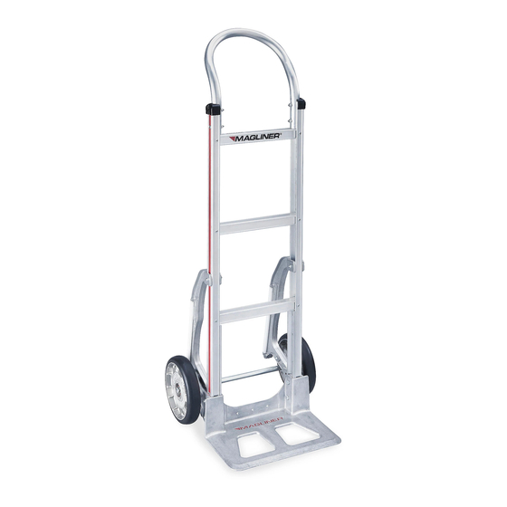
MAGLINER
ALUMINUM
®
STANDARD HAND TRUCK
WITH STAIR CLIMBER
AND SOLID RUBBER WHEELS
TOOLS NEEDED
#3 Phillips Screwdriver
7/16" Combination Wrench
or Socket Wrench
1
17
18
13
7
9
8
6
5
19
13
PAGE 1 OF 9
1-800-295-5510
uline.com
1/2" Combination Wrench
or Socket Wrench
Hammer
3
2
17
3
10
14
15
11
Pliers
PARTS
2
4
9
5
6
8
7
13
12
16
Includes additional hardware not required for assembly.
Para Español, vea páginas 4-6.
Pour le français, consulter les pages 7-9.
REF.
QTY.
DESCRIPTION
1
1
2
4
1/4"-20 x 1⁄" - Pan Head Bolt
3
6
1/4" - Locknut
4
1
Frame w/ Black Caps
5
2
Cotter Pin
6
2
Thin Washer
7
2
8
2
Thick Washer
9
2
Pin Coil Spring/Roll Pin
10
1
11
1
Right Hand (RH) Wheel Bracket
12
1
Left Hand (LH) Wheel Bracket
13
6
5/16" - Locknut
14
2
Side Channel Reinforcement
15
4
5/16"-18 x 2⁄" - Hex Head Bolt
16
1
Nose Plate
17
2
Stair Climber
18
2
1/4"-20 x 1⁄" - Pan Head Bolt
19
2
5/16"-18 x 1⁄" - Hex Head Bolt
Handle
Wheel
Axle
0521 IH-2661
Advertisement
Table of Contents

Related Manuals for U-Line Magliner H-2661


Summary of Contents for U-Line Magliner H-2661
- Page 1 Para Español, vea páginas 4-6. Pour le français, consulter les pages 7-9. π H-2661 1-800-295-5510 uline.com MAGLINER ALUMINUM ® STANDARD HAND TRUCK WITH STAIR CLIMBER AND SOLID RUBBER WHEELS TOOLS NEEDED #3 Phillips Screwdriver 1/2" Combination Wrench or Socket Wrench 7/16"...
- Page 2 ASSEMBLY ATTACH NOSE PLATE, WHEEL BRACKETS AND AXLE Position side channel reinforcements against bottom Figure 1a frame rail. (See Figure 1a) Slide nose plate into channel on side channel reinforcement, keeping Frame bolt holes aligned. (See Figure 1) 2. Insert four 5/16"-18 x 2⁄" - hex head bolts through the nose plate, side channel reinforcements and frame.
-
Page 3: Attach Wheels
ASSEMBLY CONTINUED ATTACH WHEELS Slide a thick washer onto each end of the axle. Slide a wheel onto each end of the axle. Slide a thin washer on each end of the axle. (See Figure 4) 2. Insert a cotter pin through the holes in each end of the axle. - Page 4 π H-2661 800-295-5510 uline.mx MAGLINER DIABLITO DE ® ALUMINIO ESTÁNDAR CON ADITAMENTO PARA ESCALERAS Y LLANTAS DE CAUCHO SÓLIDO HERRAMIENTAS NECESARIAS Desarmador Phillips Núm. 3 Llave Combinada o de Dado de 1/2" Llave Combinada o de Martillo Pinzas Dado de 7/16" PARTES REF.
- Page 5 ENSAMBLE COLOCACIÓN DE LA PLACA DELANTERA, LOS SOPORTES DE LA LLANTA Y EL EJE Diagrama 1a 1. Coloque los refuerzos del canal lateral contra el fondo del riel del marco. (Vea Diagrama 1a) Deslice Marco la placa delantera hacia el canal en los refuerzos del canal lateral, manteniendo alineados los orificios de los pernos.
- Page 6 CONTINUACIÓN DE ENSAMBLE COLOCACIÓN DE LAS LLANTAS Deslice una rondana gruesa en cada extremo del eje. Deslice una llanta en cada extremo del eje. Deslice una rondana fina en cada uno de los extremos del eje. (Vea Diagrama 4) 2. Inserte un pasador de chaveta a través de los orificios en cada extremo del eje.
-
Page 7: Outils Requis
π H-2661 1-800-295-5510 uline.ca MAGLINER – DIABLE DE MANUTENTION STANDARD EN ALUMINIUM AVEC ESCALADEUR ET ROUES EN CAOUTCHOUC PLEIN OUTILS REQUIS Tournevis cruciforme nº 3 Clé mixte ou à douilles de 1/2 po Clé mixte ou à douilles de Marteau Pinces 7/16 po PIÈCES QTÉ... - Page 8 ASSEMBLAGE FIXATION DE LA BAVETTE, DES SUPPORTS DE ROUE ET DE L'ESSIEU Figure 1a Positionnez les renforts de rainure latéraux contre les glissières à l'extrémité inférieure du cadre. (Voir Figure 1a) Cadre Glissez la bavette dans la cannelure des renforts de rainure latéraux en gardant les trous de boulon alignés.
-
Page 9: Fixation De La Poignée
ASSEMBLAGE SUITE FIXATION DES ROUES Enfilez une rondelle épaisse à chaque extrémité de l'essieu. Enfilez une roue à chaque extrémité de l'essieu. Enfilez une rondelle fine à chaque extrémité de l'essieu. (Voir Figure 4) 2. Insérez une goupille fendue dans le trou à chaque extrémité...
Need help?
Do you have a question about the Magliner H-2661 and is the answer not in the manual?
Questions and answers