Advertisement
Available languages
Available languages
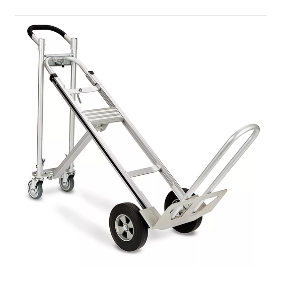
H-4124
3-IN-1 ALUMINUM
HAND TRUCK
WITH SOLID RUBBER WHEELS
TOOLS NEEDED
10mm Wrench
Pliers
1
2
3
4
9
7
6
6
8
5
Figure 1
PAGE 1 OF 6
1-800-295-5510
uline.com
13mm Wrench
Hammer
2
4
13
12
11
10
14
ASSEMBLY
14mm Wrench
PARTS
5
6
15
9
6
10
11
NOTE: Do not use air or power tools.
ATTACH HANDLE
1.
Slide handle onto the top rails of the frame. Align
holes in handle and frame. Insert two 6mm bolts
through handle and frame and secure with locknuts.
(See Figure 1)
Para Español, vea páginas 3-4.
Pour le français, consulter les pages 5-6.
REF.
QTY.
DESCRIPTION
1
1
Handle
2
2
6mm Bolt
3
2
6mm Locknut
4
1
Frame
5
2
Cotter Pin
6
8
Washer
7
2
Wheel
8
1
Axle
9
2
Round Pin
10
4
8mm Bolt
11
2
Axle Support
12
2
Frame Reinforcement
13
4
8mm Locknut
14
1
Nose Plate
15
1
Folding Nose Extension
0421 IH-4124
Advertisement
Table of Contents

Related Manuals for U-Line H-4124


Summary of Contents for U-Line H-4124
- Page 1 Para Español, vea páginas 3-4. Pour le français, consulter les pages 5-6. H-4124 1-800-295-5510 uline.com 3-IN-1 ALUMINUM HAND TRUCK WITH SOLID RUBBER WHEELS TOOLS NEEDED 10mm Wrench 13mm Wrench 14mm Wrench Pliers Hammer PARTS REF. QTY. DESCRIPTION Handle 6mm Bolt...
- Page 2 ASSEMBLY CONTINUED ATTACH NOSE PLATE, FOLDING NOSE EXTENSION Figure 2a AND AXLE SUPPORTS Position frame reinforcements against bottom frame Frame rail. (See Figure 2a) Slide nose plate into channel on frame reinforcements, keeping bolt holes aligned. (See Figure 2) 2. Align axle support with outside rail of frame. (See Figure 2) Frame 3.
- Page 3 H-4124 800-295-5510 uline.mx DIABLITO DE ALUMINIO 3-EN-1 CON LLANTAS DE CAUCHO SÓLIDO HERRAMIENTAS NECESARIAS Llave de 10mm Llave de 13mm Llave de 14mm Pinzas Martillo PARTES REF. CANT. DESCRIPCIÓN Perno de 6 mm Contratuerca de 6mm Armazón Pasador Rondana Llanta...
- Page 4 CONTINUACIÓN DE ENSAMBLE INSTALE LA BASE, EXTENSIÓN PLEGABLE PARA LA Diagrama 2a BASE Y SOPORTES DEL EJE Posicione los refuerzos del armazón contra el fondo Armazón del riel del armazón. (Vea Diagrama 2a) Deslice la base dentro del canal en los refuerzos del armazón, manteniendo los orificios de pernos alineados.
- Page 5 H-4124 1-800-295-5510 uline.ca DIABLE 3-EN-1 AVEC ROUES EN CAOUTCHOUC SOLIDES OUTILS NÉCESSAIRES Clé 10mm Clé 13mm Clé 14mm Pinces Marteau PIÈCES RÉF. QTÉ. DESCRIPTION Poignée Boulon 6 mm Écrou freiné 6 mm Cadre Goupille fendue Rondelle Roue Essieu Goupille ronde Boulon 8 mm Support d’essieu...
- Page 6 MONTAGE SUITE FIXATION DE LA BAVETTE, DE LA RALLONGE DE Figure 2a BAVETTE REPLIABLE ET DES SUPPORTS D’ESSIEU Positionnez les renforts de cadre sur le bas des rails Cadre de cadre. (Voir Figure 2a) Glissez la bavette dans le canal des renforts de cadre, en gardant les trous de boulons alignés.
Need help?
Do you have a question about the H-4124 and is the answer not in the manual?
Questions and answers