Advertisement
Available languages
Available languages
π
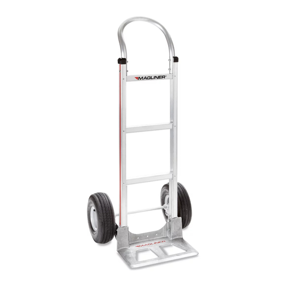
H-3376
MAGLINER
ALUMINUM
®
STANDARD HAND TRUCK
WITH PNEUMATIC WHEELS
TOOLS NEEDED
#3 Phillips Screwdriver
7/16" Combination Wrench
or Socket Wrench
1
7
9
8
6
5
13
PAGE 1 OF 6
1/2" Combination Wrench
or Socket Wrench
Hammer
3
2
10
14
15
11
1-800-295-5510
uline.com
Pliers
PARTS
2
4
9
5
6
8
7
Includes additional hardware not required for assembly.
13
12
16
Para Español, vea páginas 3-4.
Pour le français, consulter les pages 5-6.
REF.
QTY.
DESCRIPTION
1
1
2
4
1/4"-20 x 1⁄" - Pan Head Bolt
3
4
1/4" - Locknut
4
1
Frame w/ Black Caps
5
2
Cotter Pin
6
2
Thin Washer
7
2
8
4
Thick Washer
9
2
Pin Coil Spring/Roll Pin
10
1
11
1
Right Hand (RH) Wheel Bracket
12
1
Left Hand (LH) Wheel Bracket
13
4
5/16" - Locknut
14
2
Side Channel Reinforcement
15
4
5/16"-18 x 2⁄" - Hex Head Bolt
16
1
Nose Plate
Handle
Wheel
Axle
0521 IH-3376
Advertisement
Table of Contents

Related Manuals for U-Line Magliner H-3376


Summary of Contents for U-Line Magliner H-3376
- Page 1 Para Español, vea páginas 3-4. Pour le français, consulter les pages 5-6. π H-3376 1-800-295-5510 uline.com MAGLINER ALUMINUM ® STANDARD HAND TRUCK WITH PNEUMATIC WHEELS TOOLS NEEDED #3 Phillips Screwdriver 1/2" Combination Wrench or Socket Wrench 7/16" Combination Wrench Hammer Pliers or Socket Wrench PARTS...
- Page 2 ASSEMBLY ATTACH NOSE PLATE, WHEEL BRACKETS AND AXLE Figure 1a Position side channel reinforcements against bottom frame rail. (See Figure 1a) Slide nose plate into Frame channel on side channel reinforcement, keeping bolt holes aligned. (See Figure 1) 2. Insert four 5/16"-18 x 2⁄" - hex head bolts through the nose plate, side channel reinforcements and frame.
- Page 3 π H-3376 800-295-5510 uline.mx MAGLINER DIABLITO ® DE ALUMINIO ESTÁNDAR CON LLANTAS NEUMÁTICAS HERRAMIENTAS NECESARIAS Desarmador Phillips Núm. 3 Llave combinada o de dado de 1/2" Llave combinada o de Martillo Pinzas dado de 7/16" PARTES REF. CANT. DESCRIPCIÓN 1/4"-20 x 1⁄" - Perno de cabeza redondeada 1/4"...
- Page 4 ENSAMBLE COLOCACIÓN DE LA PLACA DELANTERA, LOS SOPORTES DE LA LLANTA Y EL EJE Diagrama 1a 1. Coloque los refuerzos del canal lateral contra el Armazón Frame fondo del riel del marco. (Vea Diagrama 1a) Deslice la placa delantera hacia el canal en los refuerzos del canal lateral, manteniendo alineados los orificios de los pernos.
- Page 5 π H-3376 1-800-295-5510 uline.ca MAGLINER DIABLE DE MANUTENTION STANDARD EN ALUMINIUM AVEC ROUES PNEUMATIQUES OUTILS REQUIS Tournevis cruciforme nº 3 Clé mixte ou à douilles de 1/2 po Clé mixte ou à douilles de Marteau Pince 7/16 po PIÈCES QTÉ DESCRIPTION Poignée Vis à tête cylindrique de 1/4 po-20 x 1 ½...
- Page 6 ASSEMBLAGE FIXATION DE LA BAVETTE, DES SUPPORTS DE ROUE ET DE L'ESSIEU Figure 1a Positionnez les renforts de rainure latéraux contre Frame Cadre les glissières à l'extrémité inférieure du cadre. (Voir Figure 1a) Glissez la bavette dans la cannelure des renforts de rainure latéraux en gardant les trous de boulon alignés.
Need help?
Do you have a question about the Magliner H-3376 and is the answer not in the manual?
Questions and answers