Table of Contents
Advertisement
Quick Links
Ceratherm C100 Exposed
Thermostatic Bar Shower Mixers
A7537AA
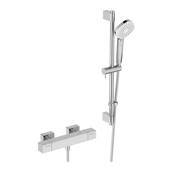
Ceratherm 100 Exposed Thermostatic Bar
Shower Mixer – supplied with 600 shower kit
A7543AA
Ceratherm C100 Exposed Thermostatic Bar
Shower Mixer – supplied over-head shower & handset kit
BEFORE CONNECTION, FLUSH WATER THROUGH PIPEWORK TO REMOVE
ALL DEBRIS ETC. WHICH COULD DAMAGE THE VALVE MECHANISM
INSTALLER:
After installation please pass this instruction booklet to user
IMPORTANT
INSTALLATION
INSTRUCTIONS
Advertisement
Table of Contents

Subscribe to Our Youtube Channel
Related Manuals for Ideal-Standard Ceratherm C100 A7537AA


Summary of Contents for Ideal-Standard Ceratherm C100 A7537AA
- Page 1 INSTALLATION Ceratherm C100 Exposed INSTRUCTIONS Thermostatic Bar Shower Mixers A7537AA Ceratherm 100 Exposed Thermostatic Bar Shower Mixer – supplied with 600 shower kit A7543AA Ceratherm C100 Exposed Thermostatic Bar Shower Mixer – supplied over-head shower & handset kit IMPORTANT BEFORE CONNECTION, FLUSH WATER THROUGH PIPEWORK TO REMOVE ALL DEBRIS ETC.
-
Page 2: Table Of Contents
TABLE OF CONTENT DIMENSIONS ....................3 PRODUCT BOX CONTENTS ..............4 INTRODUCTION ..................5 WATER SUPPLY CONDITIONS ..............6 WATER REGULATIONS ................7 PRE-INSTALLATION NOTES ..............8 INSTALLATION ..................... 9 WALL MOUNT MIXERS A7537AA &A7543AA ........... 9 INSTALLATION OF SHOWER KIT FOR A7543AA ......... 12 OPERATING PRODUCT ................ -
Page 3: Dimensions
DIMENSIONS □65 G 1/2 Basic shower valve dimensions shown with mounting brackets assembled □ □110 79,5 381,5 □ □ 30 x 15 L=1750 Shower kit & overhead shower supplied with 600 Shower kit supplied A7543AA L=1750 with A7537AA... -
Page 4: Product Box Contents
PRODUCT BOX CONTENTS A7537AA 600 Shower kit includes: 600 riser rail, a pair of mounting brackets, sliding bracket for rail, 1750 shower hose & A7537AA Shower valve shower hand set. without mounting brackets Fibre washer seals with integral strainers, -pair Wall marking template Wall mounting bracket... -
Page 5: Introduction
INTRODUCTION The fittings covered by these instructions should be installed in accord- ance with the Water Regulations published in 1999*. Ideal Standard strongly recommends that these fittings are installed by a professional fitter. *A guide to the Water Supply (Water Fittings) Regulations 1999 and the Water Byelaws 2000, Scotland is published by WRAS (Water Regulations Advisory Scheme) Unit 13, Willow Road, Pen-y-Fan Industrial Estate, Crumlin, Gwent, NP11 4EG. -
Page 6: Water Supply Conditions
WATER SUPPLY CONDITIONS Introduction These thermostatic shower mixers are manufactured to the highest standards. The mixer is intended to be installed on high pressure systems (1.0 bar or greater). The mixer has safety features such as cool body technolgy and temperature limit stop. To make installation easier, fast fix wall mounts are supplied. Ø15mm water supply pipes should be installed at 150mm horizontal centres in the wall, behind a shower panel or tiled duct wall. -
Page 7: Water Regulations
WATER REGULATIONS CATEGORIES OF RISK The water regulations published in 1999* take a new approach to backflow in that they look at different categories of risk. The installer must assess the risk from the various categories of fluid in adjacent appliances before determining the level of backflow protection required for a particular installation. -
Page 8: Pre-Installation Notes
PRE-INSTALLATION NOTES The thermostatic mixing valve must be installed in such a position that maintenance of the TMV, its valves and the commissioning and testing of the TMV can be undertaken. Ceratherm C100 is an exposed two hole thermostatically controlled shower mixer. This product is designed to provide water from ambient cold up to a safe maximum temperature for bathing. -
Page 9: Installation
INSTALLATION IMPORTANT BEFORE CONNECTION, FLUSH WATER THROUGH PIPEWORK TO REMOVE ALL DEBRIS ETC. WHICH COULD DAM- AGE THE VALVE MECHANISM Wall mount mixers A7537AA &A7543AA Pair of wall brackets with connectors & WALL MOUNTING escutcheons BRACKETS Template x1 Ø15mm copper supply pipes should be run within the wall cavity. Hot supply pipe should be on the left hand side and the cold on the right. - Page 10 Place the brackets over the exposed pipes and use the template provided to position them 150mm apart. Mark the hole positions for the fixings onto the mounting surface. Ensure that the positions of the holes will not result in damage to the pipework inside the wall cavity during drilling.
- Page 11 Slide the olives onto the pipes. Screw the two connectors onto the wall brackets by hand until they stop against the olives. Use a 23mm A/F spanner (or adjustable) on the connectors to tighten. The connectors will have to be securely tightened to form the necessary compres- sion joint between the olive, wall bracket &...
-
Page 12: Installation Of Shower Kit For A7543Aa
Installation of Shower kit for A7543AA Once the shower valve has been securely fitted, work can commence on the installing the shower kit. Start by assembling the shower rail parts together: 1. Slide the wall fixing bracket onto the shower riser rail, orientated as shown. - Page 13 5. Once the riser rail is correctly positioned & is vertical, draw a line around the perimeter of the bracket onto the wall surface. Lift the shower rail assembly off the nipple on the shower valve & place it safely to one side. 6.
- Page 14 9. Refit the shower rail assembly back onto the nipple on the shower valve. Align the bracket on shower rail to the circular bracket fitted to the wall. Press firmly to ensure the bracket on the shower rail makes contact with the wall. Using a 2.5mm hexagonal key, tighten the grub screw on the top of the bracket to secure the riser rail assembly at the top.
- Page 15 Wall bracket for Category-5 shower hose retaining applications Product A7543AA includes a small “shower hose” retaining bracket, which should be fitted to ensure the installation complies with water regulations, see section 5 for more details. Select a suitable location on the wall that will prevent the flexible shower handset from entering any adjacent appliances, such as sink, washbasin, toilet, bath, bidet, or shower tray.
-
Page 16: Operating Product
OPERATING PRODUCT Shower mixer handle controls Q= flow rate Q=0% Q=50% Q=100% ATTENTION: TEMPERATURES HIGHER THAN 40°C CAN BE HARMFUL TO YOUR HEALTH. Right handle controls water flow rate & outlet device • This handle is shown above parked in the off position (giving no flow at this position). •... -
Page 17: Temperature Adjustment
Q=0% Q=50% Q=100% Right handle controls the 3 function diverter (for product A7543AA only): • This handle is shown above parked in the off position (giving no flow at this position). • Rotating this handle downwards from the parked position, commences water flow & will direct water to the bottom outlet of the mixer. -
Page 18: Commissioning & Periodic Checks
COMMISSIONING & PERIODIC CHECKS The following procedures should be carried out after installation and every 12 months after to ensure that the valve is functioning correctly. Check that: 1. The application of the thermostatic valve matches the approved designation. 2. The supply pressures are within the recommended range for the application. 3. -
Page 19: Cold Water Isolation (Cwi) Test
COLD WATER ISOLATION (CWI) TEST CWI test is a guide to showing the performance of the thermostat. Prior to CWI test: • Make sure that the temperature handle is aligned in the 40°C position. • Make sure the supply temperatures are within the ranges 55 to 65°C for hot, & 5 to 20°C for cold. •... -
Page 20: Disassembly Sequence Of Maintenance
THERMOSTATIC CARTRIDGE AGEING Following many years of normal service you may notice the following: 1. The need to carry out more frequent adjustment of mixed temperature. 2. The thermostatic element may not pass the CWI test. These issues could be due to the ageing of the thermostat which loses some expansion capability over time. - Page 21 Method for demounting mixer: 1. Observe disassembling sequence, as detailed in section 14, steps 1 & 2. 2. Remove the overhead shower assembly, if fitted (A7543AA only). 3. Slide back both escutcheons away from the wall towards the mixer body. Undo the two coupling nuts located at the rear of the mixer (see fig above).
-
Page 22: Handle Removal For Cartridge Access
HANDLE REMOVAL FOR CARTRIDGE ACCESS Drive bush Left handle for Right handle for temperature flow & divert To gain access to either the thermostatic, flow or diverter cartridges, it will be necessary to remove the appropriate handle. 1. Carefully prise out the rubber plug fitted either at the rear of the handle (left side) or the underside of the handle (right side). -
Page 23: Thermostatic Cartridge Replacement
THERMOSTATIC CARTRIDGE REPLACEMENT Cartridge stop max. 5 Nm Use the following method to inspect or replace the thermostatic cartridge: 1. Observe the disassembling sequence, see section 14, steps 1 to 3. 2. Remove the temperature control handle (left side) as detailed in section 16. Remove also the drive bush fitted to the spindle of the thermostat. -
Page 24: Flow Cartridge Replacement A7537Aa
Arrow min. 4 Nm marker max. 5 Nm Threaded collar Rotate spindle clockwise, Stop left port shown closed. sleeve Handle corner with button Arrow Shower marker symbols 7. With the cartridge located back in the mixer bore, screw the threaded collar into the mixer body by hand first &... -
Page 25: Check-Valve Replacement
1. Remove the flow control handle (right side) as detailed in section 16. Remove also the drive bush fitted to the spindle of the flow cartridge. Note: the square end cap can remain inside the mixer body. 2. Slide off the stop ring. 3. -
Page 26: Spare Parts A7537Aa
SPARE PARTS A7537AA A7537AA Pos. Description Part No. Qty. Ceratherm C100 Exposed Handle cpl. A 861 545 AA 1 Set Thermostatic Bar Shower Thermostatic Cartridge A 861 371 NU 1 pcs Mixer – supplied with 600 shower kit Stopring A 861 373 NU 1 pcs Cartridge G1/2 180°... -
Page 27: Spart Parts A7543Aa
SPART PARTS A7543AA A7543AA Ceratherm C100 Exposed Thermostatic Bar Shower Mixer – supplied over-head shower & handset kit Shower hose 1750 mm A 4109 AA 1 pcs Pos. Description Part No. Qty. Handspray 1Func. BD 320 AA 1 pcs Handle cpl. A 861 545 AA 1 Set Shower bar 1100 mm... -
Page 28: Inline Service Valves
INLINE SERVICE VALVES Inline service valves (not supplied with this product) MUST be fitted to permit future maintenance of the cartridges. They also facilitate the cold water isolation test. These should be fitted as close as is practicable to the water supply inlets of the thermostatic shower valve.
Need help?
Do you have a question about the Ceratherm C100 A7537AA and is the answer not in the manual?
Questions and answers