
Related Manuals for Sleipner SEP60


Summary of Contents for Sleipner SEP60
- Page 1 Installation Guide For Pro DC Electric Thruster Models SEP60 DOCUMENT ID: SLEIPNER AS 2721 REVISION: P.O. Box 519 DATE: N-1612 Fredrikstad 2021 Norway LANGUAGE: www.sleipnergroup.com...
-
Page 2: Table Of Contents
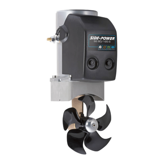
Product Spare Parts and Additional Resources ..........................25 Warranty Statement .................................... 25 Products SE60/185S2-12V - SE60 Tunnel bow/stern thruster, 12V SE60/185S2-24V - SE60 Tunnel thruster, 24v Sleipner Motor AS P.O. Box 519, Arne Svendsensgt. 6-8 N-1612 Fredrikstad, Norway MC_0020 SEP60... -
Page 3: Responsibility Of The Installer
Sleipner products. The recommendations given in this document are guidelines ONLY, and Sleipner strongly recommends that advice is obtained from a person familiar with the particular vessel and applicable regulations. - Page 4 Sleipner products. If you are interfacing the S-Link™ bus by agreement with Sleipner through a designated Sleipner supplied interface, you are still required to install at least one original Sleipner control panel to enable efficient troubleshooting if necessary.
-
Page 5: Thruster Measurements
T (max) Maximum tunnel wall thickness 0.24 0.24 *Valid for SE & SEP Propeller position will vary with each thruster model Single Propeller The gear leg/ propeller(s) must never extend out of the tunnel Tunnel centre line MG_0079 SEP60 2721 2021... -
Page 6: Thruster Specifications
- Flexible coupling between electro-motor and drive shaft protects electro motor and gear system if propeller jams. - Original Sleipner panels shut off automatically 6 minutes after last use. This interval can be adjusted in 5 min steps up to 60 minutes or turned off completely. -
Page 7: Positioning Of The Tunnel / Thruster
(NB: This can be overlooked depending on the installation methods defi ned in this manual.) Pivot point important Lowered rotation power performance Stronger rotation power performance Water line Ø min 1/4 Ø (Recommended) min 1/4 Ø (Recommended) MG_0001 SEP60 2721 2021... -
Page 8: Tunnel Length
The gear leg/ propeller(s) must prevent a circular water vacuum Increase tunnel length to protect never extend out of the tunnel cavity between the propeller and the propeller from water forces the hull of the boat. when high-speed cruising. MG_0048 SEP60 2721 2021... -
Page 9: Tunnel Installation In Sailboats
This installation is being used by some of the world’s largest sail boat builders and has proven to give little to no speed loss during normal cruising. This can also be an installation method for flat bottomed barges to avoid extremely long tunnels and large oval tunnel openings in the hull. Pos. A Pos. B MG_0004 SEP60 2721 2021... -
Page 10: Water Deflection
(NB: As a rule, you should not see the back face of the tunnel when standing directly in front of the boat looking aft.) High water force while underway High water force while underway from wave contact MG_0003 SEP60 2721 2021... -
Page 11: Tunnel Ends
(NB: A Side-power thruster propeller does not produce cavitation at working speed. Therefore, any cavitation and cavitation noise in the tunnel will be caused during improper tunnel installation.) R = 0,1 x D (10%) Cavitation Angled tunnel ends for steel/ aluminium hulls MG_0002 SEP60 2721 2021... -
Page 12: Tunnel Installation
(NB: Ensure gaps between the tunnel and the hull are completely fi lled with resin/ fi breglass. In areas where you can not access to make layers of resin/ fi breglass, a resin/ fi breglass mixture must be used in that area.) 8 x layers of fiberglass and resin 8 x layers of fiberglass and resin MG_0005 SEP60 2721 2021... - Page 13 Additional Layers of Hull fiberglass and resin Welding Tunnel *Fiberglass *Steel/ Hull Aluminium Hull Hull R = D x 0,1 Layers of fiberglass R = D x 0,1 and resin Tunnel Additional Layers of fiberglass and resin MG_0006 SEP60 2721 2021...
-
Page 14: Stern Tunnel Installation
Stern Tunnel Installation MC_0003 For Stern Thruster installation please refer to the supplied manual in your Sleipner product delivery Installation Guide Stern Thruster SLEIPNER AS DOCUMENT ID: P.O. Box 519 REVISION: DATE: N-1612 Fredrikstad Norway www.sleipnergroup.com LANGUAGE: SEP60 2721 2021... -
Page 15: Gear Leg & Motor Bracket Installation
Motor bracket Ensure propeller turns without Apply MS Polymer obstruction sealant or equal to 6 - 7 both sides of the gasket IMPORTANT Fasten bolts Do not apply sealant to 18Nm (13.28 lb/ft) the holes. Motor bracket MG_0027 SEP60 2721 2021... -
Page 16: Propeller Installation
Apply anti-fouling to the gear leg and propeller. Do not apply anti-fouling to any rubber elements of the gear leg or anodes. Drive pin Propeller Washer Lock nut Anode Anti-fouling Anode holding screw Apply Loctite 243 or similar MG_0028 SEP60 2721 2021... -
Page 17: Motor Installation
On completion of operations, the cover must be removed before operating the thruster. Coupling Turn gear leg shaft so the motor coupling fits into the slots. Drive Pin Gasket > 30° Motor FASTEN (18 Nm) (13.28 lb/ft) Motor support IMPORTANT Do not position support on the motor cap. MG_0029 SEP60 2721 2021... -
Page 18: Thruster Electrical Installation
23 Nm (16.96 lb/ft) IMPORTANT Do NOT use washers between lugs, this causes overheating and fire. Spring washers must be placed in the outer Lugs Spring Spring position before tightening nut. washer washer MG_0021 SEP60 2721 2021... -
Page 19: Electrical Specifications
Electrical Specifi cations MC_0044 SEP60 2721 2021... -
Page 20: Technical Wiring Diagram
Technical Wiring Diagram To PPC grey blue 8-Way connector Multi cable to PPC white pink (Opt.) Thruster motor To PPC MG_0062 SEP60 2721 2021... -
Page 21: S-Link System Description
MC_0120 S-Link is a CAN-based control system used for communication between Sleipner products installed on a vessel. The system uses BACKBONE Cables as a common power and communication bus with separate SPUR Cables to each connected unit. Units with low power consumption are powered directly from the S-Link bus therefore one power cable must be connected to the BACKBONE Cable through a T-Connector. -
Page 22: Control Panel Cable Installation
(NB: If two or more control panels are operated at the same time in opposite directions, the electronic control box will stop the thruster until it receives a single signal or thrust in one direction.) • Sleipner on/off equipment it is entirely “plug & play” and require no additional confi guration setup. See the Control panel manual for more information. PJC 212... -
Page 23: Control Panel Installation
Control Panel Installation MC_0398 For Control Panel installation please refer to the supplied manual in your Sleipner product delivery Installation Guide Control Panel SLEIPNER AS DOCUMENT ID: P.O. Box 519 REVISION: DATE: N-1612 Fredrikstad Norway www.sleipnergroup.com LANGUAGE: SEP60 2721 2021... -
Page 24: Pre-Delivery Checklist
Correct drive direction as per control panel: ..............................The compartment for the thruster has been isolated from general bilge water and has no obvious or suspected risks for flooding: .................................................................................................................................. Other comments by installer: ........................................................................................................................SEP60 2721 2021... -
Page 25: Service And Support
10. This warranty gives you specific legal rights, and you may also have other rights which vary from country to country. Patents MC_0024 At Sleipner we continually reinvest to develop and offer the latest technology in marine advancements. To see the many unique designs we have patented visit our website www.sleipnergroup.com/patents SEP60... - Page 26 Notes MC_0037 ..............................................................................................................................................................................................................................................................................................................................................................................................................................................................................................................................................................................................................................................................................................................................................................................................................................................................................................................................................................................................................................................................................................................................................................................................................................................................................................................................................................................................................................................................................................................................................................................................................SEP60 2721 2021...
- Page 27 Notes MC_0037 ..............................................................................................................................................................................................................................................................................................................................................................................................................................................................................................................................................................................................................................................................................................................................................................................................................................................................................................................................................................................................................................................................................................................................................................................................................................................................................................................................................................................................................................................................................................................................................................................................................SEP60 2721 2021...
- Page 28 © Copyright Sleipner Motor AS, 2021 The information given in the document was correct at the time it was published. However, Sleipner Motor AS can not accept liability for any inaccuracies or omissions it may contain. Continuous product improvement may change the product specifi...
Need help?
Do you have a question about the SEP60 and is the answer not in the manual?
Questions and answers