Table of Contents
Advertisement
Advertisement
Table of Contents

Related Manuals for Pool Pro CPP Series


Summary of Contents for Pool Pro CPP Series
-
Page 2: Table Of Contents
TABLE OF CONTENTS Important Warnings and Safety Instructions ..................... 3 Important Warnings ........................ 3 1.2 Important Safety Instructions ....................3 1.3 Important Water Balance Information ..................3 General Overview ............................4 2.1 Recommendations and Helpful Hints ..................4 Contents ..........................4 Tools Needed .......................... 4 Pool Preparation ............................5 Power Pack & Cell Electrode Installation ....................6 - 7 4.1 Power Pack Installation ...................... -
Page 3: Important Warnings And Safety Instructions
• Only add chemicals in the method and quantities as indicated on the packaging provided or advised by your local Pool Pro Professional. If in doubt of any results you achieve, do not hesitate to consult with your local Pool Pro Professional. -
Page 4: General Overview
While every effort has been made to ensure that the information contained in this guide is accurate and complete, no liability can be accepted for any errors or omissions. Pool Pro reserves the right to change the specifications of the hardware and software described herein at any time without prior notice. -
Page 5: Pool Preparation
This is a guide only, does not constitute and should not be used as an alternative to specific professional advice. Pool Pro and The POPS Group Pty Ltd accept no liability for any damage, loss or harm associated with the use of this guide. -
Page 6: Power Pack & Cell Electrode Installation
4. POWER PACK & CELL ELECTRODE INSTALLATION 4.1 Power Pack Installation • The Pool Pro Power Pack has an Ingress Protection Rating of IP23 enabling it to be installed outdoors. Regulations require that the Power Pack shall be installed outside the pool zone. -
Page 7: Installation Diagram
4. POWER PACK & CELL ELECTRODE INSTALLATION 4.3 Installation Diagram POWER PACK (Ensure good ven la on) WARNING: DO NOT plug in if carton has been wet. CELL Water turbulance has less impact FILTER on plates with entry this end but Cell can be plumbed either way. -
Page 8: Power Pack Operation
5. POWER PACK OPERATION 5.1 Timer Switch This switch position determines whether the unit is manually turned on or automatically controlled by the Timer. • Auto Position - the time clock controls the operating hours. See section 6 for Timer Setting. •... -
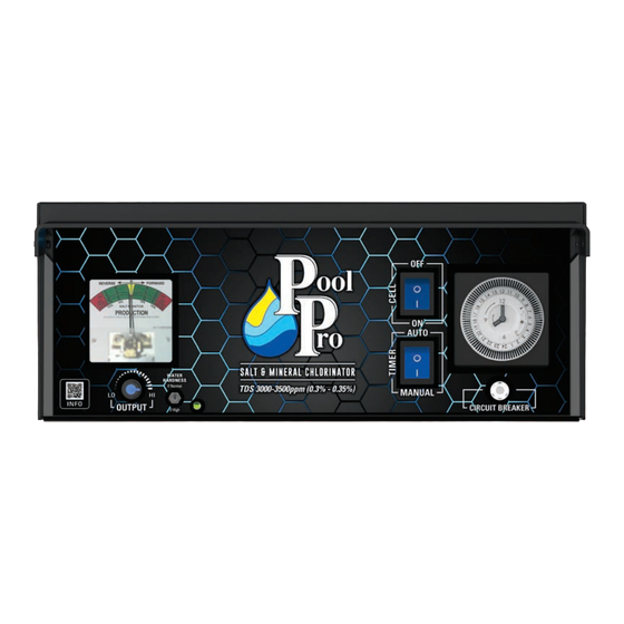
Page 9: Production Output Display Meter
• If the needle reaches the RED then you have either just enough salt (if just reaches RED) or too much salt (if it goes in to the RED). If unsure refer to your nearest Pool Pro Professional for a water test before adding more salt. -
Page 10: Timer Setting
6. TIMER SETTING Your Pool Pro unit comes with a simple to operate quartz mechanical Timer which has a built in battery back up function. This area of set up is critical and we recommend you take time to read it and understand why we recommend certain settings. - Page 11 6. TIMER SETTING To adjust the time of the clock, simply hold the outside of the white segments and turn the dial until the clock reads the right time and the number near the timer on/off arrow is close to the same number. This time is set at 8:00am and the dial pointer shows the 8:00 position as does the clock face hands The Timer comes on where the pins that are...
-
Page 12: Applying A Chlorinator Skin/Front Sticker (Cpps Model Only)
7. APPLYING A CHLORINATOR SKIN/FRONT STICKER (CPPS MODEL ONLY) 1. Remove the two Rivet Clips and the Acrylic Cover, and set them aside (see below diagrams). 2. Gently wipe the existing skin/sticker to remove any dust/dirt/oils, ensure it is clean & dry. RIVET CLIPS &... -
Page 13: Chlorinator Maintenance
Cell Housing. For cleaning, please follow these steps: • Switch off the wall outlet switch as this ensures the pump and Pool Pro unit will not turn on. • Unscrew the Cell Locking Ring and remove the electrode for inspection. If calcium build-up is present, immerse the electrode in Pool Pro Cell Cleaner. -
Page 14: Inspecting And Cleaning The Power Pack
The Pool Pro Power Pack has air vents to allow internal components to remain cool. A special oil is applied to the inside of the unit during production to stop insects from entering the unit. To help assist in keeping the insects away, apply a surface spray periodically on the wall or post that the unit is mounted on. -
Page 15: Chlorinator Troubleshooting
8. CHLORINATOR TROUBLESHOOTING 9.3 Green LED near the Soft/Hard switch flashing Remedy Potential Cause This indicates power is supplied to the PCB and is normal This is not a fault but purely an indicator 9.4 Low output reading on the Salt Meter Remedy Potential Cause Turn the Knob clockwise,the reading should increase... -
Page 16: Schematics And Part Numbers
10. SCHEMATICS AND PART NUMBERS... - Page 17 10. SCHEMATICS AND PART NUMBERS CODE DESCRIPTION CODE DESCRIPTION 1 PPN00037 CPP/CPPS ALUMINIUM CHASIS CPP/CPPS CABLE GROMMET 24 PPN00034 2 PPN00039-1 CPP/CPPS FRONT COVER BLACK 6N-4 3 PPN00060 CPP/CPPS FRONT STICKER 25 PPN00042 CPP/CPPS SCR BRIDGE LONG 4 PPN00033 CPP/CPPS ACRYLIC FRONT 26 PPN00043 CPP/CPPS SCR BRIDGE SHORT 5 PPN00038...
-
Page 18: Specification Table
11. SPECIFICATION TABLE Domestic Models available: Chlorine* VOLTS AMPS* VOLTS* AMPS* Power* MODEL Frequency (g/hr) Weight Dimensions (Vac) (Aac) (Vdc) (Adc) Consumption @3500 (Hz) (kg) (cm) NUMBER Input Input Output Output (Watts) ppm salt CPP20 210 – 265 1.02 6.60 CPP30 210 –... -
Page 19: Warranty And Product Registration
THIS EQUIPMENT HAS BEEN MANUFACTURED AND TESTED TO THE HIGHEST STANDARD AND ACCORDINGLY CARRIES THE FOLLOWING WARRANTY. The Pool Pro Power Pack and Electrolytic Cell will be repaired at no charge for a period of 12.1 three (3) years from the date of purchase should it be found, after examination, that the failure has been caused by faulty workmanship or materials. -
Page 20: Technical Support
Pool Pro Professional for comprehensive advice. This guide includes subject(s) that should only be performed by or under the direction and advice of your local Pool Pro Professional and under no circumstances should the guide be used as a substitute for such professionals.
Need help?
Do you have a question about the CPP Series and is the answer not in the manual?
Questions and answers