Table of Contents
Advertisement
Quick Links
CHAINTECH
Declaration of Conformity
According to 47 CFR, Parts 2 and 15 of the FCC Rules
9EJS1
The following designated product:
EQUIPMENT: MAINBOARD
MODEL NO.: 9EJS1
Intel® Socket 478
Intel® 845PE + ICH4
ATX Motherboard
is a Class B digital device that complies with 47 CFR Parts 2 and 15 of the FCC
Rules. Operation is subject to the following two conditions:
1. This device may not cause harmful interference.
2. This device must accept any interference received, including interference that
may cause undesired operation.
User's Manual
This declaration is given to the manufacturer:
CHAINTECH-EXCEL COMPUTER INC.
4427 Enterprise St. Fremont, CA 94538, U.S.A.
http://www.chaintech-excel.com
Chaintech President: Simon Ho
Signature:
Version 1.0
Advertisement
Table of Contents

Related Manuals for CHAINTECH 9EJS1


Summary of Contents for CHAINTECH 9EJS1
- Page 1 According to 47 CFR, Parts 2 and 15 of the FCC Rules 9EJS1 The following designated product: EQUIPMENT: MAINBOARD MODEL NO.: 9EJS1 Intel® Socket 478 Intel® 845PE + ICH4 ATX Motherboard is a Class B digital device that complies with 47 CFR Parts 2 and 15 of the FCC Rules.
- Page 2 Chapter 1: Introduction * This device may not cause harmful interference. This chapter describes the features of the 9EJS1 motherboard. It includes brief * This device must accept any interference received, including interference that may cause undesired operation. descriptions of the special features of the motherboard and the new technology it This equipment has been tested and found to comply with the limits for a Class B digital device, pursuant to supports.
-
Page 3: Table Of Contents
Thiz-Linux Desktop 6.0 Setup Steps ..... 68 Chapter 6 1-2 Package Contents.....................3 1-3 CHAINTECH’s Special Features: ..............4 6-1 BEFORE YOU START .................68 1-4 9EJS1 Motherboard Diagram ................7 6-2 HOW TO INSTALL ..................69 1-5 9EJS1 Motherboard Layout................8 Appendix.................. 95 Hardware Setup ............9 Chapter 2 Digidoc 80-Port POST Error Code List...............95... -
Page 4: Chapter 1 Introduction
Chapter 1 Chapter 1 USB 2.0/1.1 Host Controller Introduction Chapter 1 One EHCI USB 2.0 Controller and 2 UHCI USB 1.1 Controllers. 1-1 Product Specifications Support total 6 USB 2.0 Ports (USB1.1 compatible). Support USB 2.0 High-Speed Device @480 Mb/s Transfer Rates. Processor Supports Intel®... -
Page 5: Package Contents
Chapter 1 Chapter 1 1-2 Package Contents 1-3 CHAINTECH’s Special Features: This product comes with the following components: CBOX™2, CHAINTECH’s exclusive front panel. 1. Motherboard Include: 2. I / O Panel USB (1.1 / 2.0 compliant) Ext. ports 3. Round Cable Earphone (∅... - Page 6 Acrobat eBook Reader. Imagemore. AutoSave. Zenith Key Chain 6channel kit Round Cable THIZ Linux CD World's first 60cm Round Cable bundle brought to you by CHAINTECH, an innovative streamliner ribbon cable provides better overall system stability and neatness. IEEE 1394 USB2.0 RAID...
-
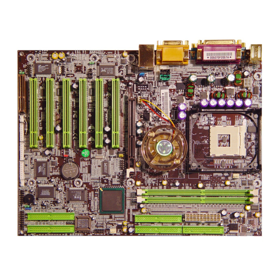
Page 7: 9Ejs1 Motherboard Diagram
Chapter 1 Chapter 1 1-4 9EJS1 Motherboard Diagram 1-5 9EJS1 Motherboard Layout... -
Page 8: Chapter 2 Hardware Setup
Chapter 2 Chapter 2 2-2 Setting your CPU’s Parameters Hardware Setup Chapter 2 “Hyper-Threading Functionality Requirement” Content If your motherboard has already been installed in your computer you may still need To enabling the functionality of Hyper-Threading Technology for your computer to refer to this chapter if you plan to upgrade your system's hardware. -
Page 9: Main Memory Configuration
Chapter 2 Chapter 2 2-3 Main Memory Configuration 2-4 Connector and Jumper Reference Chart This motherboards provides 2 184pin Double Data Rate (DDR) Dual Inline Memory Modules (DIMM) slots. Which supports PC 1600/PC2100/2700 DDR SDRAM Jump Connector Function Page modules up to 2GB. Install at least one DIMM module on the slots. Memory PW 1/2 ATX Power Supply Connector modules can be installed on the slots in any order. -
Page 10: Connector And Jumper Settings
USB connector. In case of such exposure, the poly-fuse will immediately be disconnected from the circuit, just like a normal fuse. All cables that provided by CHAINTECH come with a security-proof. After being disconnected for a certain period of time, the poly-fuse will return to its PW 1 / 2 (ATX Power Supply Connector): normal state. - Page 11 Chapter 2 Chapter 2 than [4 seconds] will switch the system completely off. See Over-ride Power connect 34 pins of Floppy. Button Operation diagram. IDE 1/2 (IDE Hard-Disk Connector) 2. P-LED (Power LED Connector): The power indicator LED shows the system's power status. It is important to pay attention to the correct cables and pin orientation (i.e., not to reverse the order of these two connectors.) 3.
- Page 12 Chapter 2 Chapter 2 JP1 (CMOS Clear Jumper): in the BIOS's Power On Management screen. You must also set this jumper's cap to pins 2-3 to use this function. Definition JP6/JP6A/JP24 (Enable/Disable USB 0/1, 2/3, 4/5 Device Power ON Jumper) 1-2 Normal (default) 2-3 Clear CMOS Data Definition...
- Page 13 Chapter 2 Chapter 2 JP11 (On board LAN Enable/Disable Jumper): FAN1/FAN2/FAN3 (CPU/System/ North Bridge Cooling Fan Connectors): Definition Enable (default) Disable This Function allows you to enable or disable the on board LAN. You must set the The board's management extension hardware is able to detect the CPU and system fan speed in rpm (revolutions per minute).
- Page 14 Chapter 2 Chapter 2 CN3 (Auxiliary Audio-in Connector): CN4C (SPDIF KIT Connector): The SPDIF-in/ out connector supports the digital audio. This connector must be connected to the cable from an external device. Connect the SPDIF bracket to this This connector is for Auxiliary Audio-in Device. connector.
- Page 15 Chapter 2 Chapter 2 CN5A [WOM (Wake-on-Modem) Connector]: CN17 (Blue LED Connector): Enable the Wake Up On Modem selection in BIOS's Power Management Menu to These features work entirely the same as the power indicator LED, both shows the use this function. This header is used to connect an add-in modem card, which gives system’s power status.
- Page 16 CN25 (CBOX™ 2 DigiDoc System Display Connector): These connectors are for the bundled IEEE 1394 serial connector cables that connect CBOX™ 2 features CHAINTECH’s exclusive DigiDoc, the most advance system to the IEEE 1394 bracket. Attach the cable to these connectors, and the CBOX™2 diagnostic monitoring display.
-
Page 17: Cbox™ 2 Setup
IEEE-1394 Cable (8 pin) It is recommended that you leave the default setting to prevent any burn out on 80 Port Display (10 pin) Green Mode LED Cable (2 pin) your CPU. All cables that provided by CHAINTECH come with a security-proof. -
Page 18: Chapter 3 Bios Setup Program
Chapter 3 Chapter 4 3-1 Standard CMOS Setup BIOS Setup Program Chapter 3 The Standard CMOS Setup allows users to configure system components such as Phoenix-Award BIOS ROM has a built-in setup program that allows users to modify hard disk drive, floppy disk drive and video display as well as date, time and the basic system configuration. -
Page 19: Advanced Bios Features
Chapter 3 Chapter 4 3-2 Advanced BIOS Features First/Second/Third/Boot Other Device: By choosing the Advanced BIOS Features option from the CMOS Setup Utility This option sets the sequence of drives BIOS attempts to boot from after POST menu (Figure 3-1), the screen below is displayed. This sample screen contains the completes. -
Page 20: Advanced Chipset Features
Chapter 3 Chapter 4 OS Select (For DRAM >64MB): 3-3 Advanced Chipset Features If your system's DRAM is larger than 64MB and you are running OS/2 , select OS/2 By choosing the [Advanced Chipset Features] option from the CMOS Setup as the item value. -
Page 21: Integrated Peripherals
Chapter 3 Chapter 4 3-4 Integrated Peripherals 3. IDE Primary/Secondary Master/Slave UDMA: This section provides information on setting peripheral devices. By choosing the Ultra DMA implementation is possible only if your IDE device supports it and Integrated Peripherals option from the CMOS Setup Utility menu (Figure 3-1), the your operating environment contains a DMA driver. - Page 22 Chapter 3 Chapter 4 USB Controller: Enable the on-board Universal Serial Bus (USB V1.1 or V2.0) controller if you want to connect a USB device to your system. Note that if this setting is disabled, you can still temporarily use a USB keyboard during boot up so that you can enter BIOS and enable this setting.
-
Page 23: Power Management Setup
Chapter 3 Chapter 4 3-5 Power Management Setup selected Blank. This function serves as both a screen saver and a power saver. This section provides information on the Green PC power management functions. 3. DPMS Supported - Select this option if your video card supports the Display By choosing the Power Management Setup option from the CMOS Setup Utility Power Management Signaling (DPMS) standard (i.e., you have a monitor that menu (Figure 3-1), the screen below is displayed. -
Page 24: Pnp/Pci Configurations
Chapter 3 Chapter 4 3. Wake up on LAN: 3-6 PNP/PCI Configurations When enabled, a LAN that receives a signal will wake up the system from soft off This section provides IRQ and DMA setting information. By choosing the PNP/PCI Configuration option from the CMOS Setup Utility menu (Figure 3-1), the screen and green mode. -
Page 25: Pc Health Status
Chapter 3 Chapter 4 3-7 PC Health Status 3-8 Frequency/Voltage Control By choosing the PC Health Status option from the CMOS Setup Utility menu By choosing the Frequency/Voltage Control option from the CMOS Setup Utility (Figure 3-1), the screen below is displayed. This field shows you the current system menu (Figure 3-1), the screen below is displayed. -
Page 26: Load Fail-Safe Defaults
Chapter 3 Chapter 4 3-9 Load Fail-Safe Defaults Load Fail-Safe Defaults loads the default BIOS values directly from the CMOS 3-13 Exit Without Saving Setup Utility menu (Figure3-1). If the stored record created by the setup program Selecting this option and pressing Y followed by the [Enter] key lets you exit the becomes corrupted and therefore unusable, these defaults will be loaded Setup program without recording any new values or changing old ones. -
Page 27: Chapter 4 Driver Setup
Chapter 4 Chapter 4 3. Click [Yes] to accept the license agreement DRIVER Setup Chapter 4 Insert the support CD that come with your motherboard into your CD-ROM driver or double-click the CD drive icon in [ My computer ] to open the setup screen. 4. -
Page 28: Intel® Application Accelerator Setup
Chapter 4 Chapter 4 5. Please, select [Finish] after restart 2. Click [Next] to start software installation 4-2 Intel® Application Accelerator Setup 3. Click [Yes] to accept the license agreement 1. Click [Ultra ATA storage driver]... -
Page 29: Intel® Lan Driver Setup
Chapter 4 Chapter 4 4. Click [Next] to continue installation 6. Select , click [Finish] to complete setup 4-3 Intel® LAN Driver Setup 5. Click [Next] to continue installation 1. Click [LAN Driver]... -
Page 30: C-Media Sound Driver Setup
Chapter 4 Chapter 4 2. The program will automatically install it self. 4-4 C-MEDIA Sound Driver Setup This section provides information on installed audio devices by choosing [Audio Drivers] from the Setup Driver menu. 1. Please select [Audio Drivers] 3. Click [Finish] to complete setup 2. - Page 31 Chapter 4 Chapter 4 3. Please select [OK] 6. Please select [Next] 4. Please select [Next] 7. Please wait; select [OK], after restart. 5. Please select [Next] 8. Select different channels according to you speakers...
-
Page 32: Audio Device Application
Chapter 5 Chapter 4 Audio Device Application Chapter 5 C-Media Mixer Volume This sound card supports Windows 95/98/ME/NT4.0/2000 operating systems. To start 1. Volume Control the Audio Application Program simply select the [Start]→[Program Files]→[PCI Audio Applications]→[Audio Rack] It includes the following options: 1. - Page 33 Chapter 5 Chapter 4 Mixer Advance Setting: b) Speakers: a) SPDIF: i) Headset & 2 channel speaker setup i) Output: S/PDIF Playback: To activate SPDIF OUT. (S/PDIF Out only on earphone and 2 speakers. Sampling Rate: Transfer the Wave file from the computer through optical fiber out to any digital media devices, ex.
- Page 34 Chapter 5 Chapter 4 iv) User 4ch XeaR mode setup e) Option: v) User 6ch XeaR mode setup 【Enable Hot-Key Setting】 This provides settings for Hot-Keys for Volume control, Mute, and Display. 【Enable Microphone Booster】 Enable the microphone’s electrical circuit to increases the sensitivity of the microphone.
- Page 35 Chapter 5 Chapter 4 CD Player Output Configuration: MIDI Player Output Configuration: Setup: Setup: 1. Under Win 95 / 98 1. Enable to choose the Audio CD drive of your system. 3 options available for Output device: [Default MidOut Device], [MPU-401], 2.
- Page 36 Chapter 5 Chapter 4 MP3 WAV Player Configuration: [Help]: Sound Effecter Setting Button: 1. Reverberation: This is to setup the depth of the sound environment. 2. Equalizer: This is to setup the high and low pitch of the sound frequency output. 3.
-
Page 37: Multi- Channel Demo
Chapter 5 Chapter 6 5-3 Multi- Channel Demo Thiz-Linux Desktop 6.0 Setup Steps Chapter 6 [ STAR ] → [ Program ] → [ PCI Audio Applications ] → [ Multi-Channel Demo ] Thank you for selecting Thiz Linux Desktop 6.0, before you install please pay attention to the following requirements and specifications. -
Page 38: How To Install
Chapter 6 Chapter 6 6-2 HOW TO INSTALL Step 1. Language Selection (for installation program) To start installations set up your CD-ROM device. Then insert the Thiz Linux 6.0 The first step of installation is to select the language for the installation program. CD-ROM into the CD-ROM driver and switch on the computer. - Page 39 Chapter 6 Chapter 6 Keyboard configuration includes: If you select “ Have the installer automatically partition for you “ the following window will appear. Items Descriptions The system has already detected the model of keyboard you are using, please check clearly; if there is any mistake, please select Model your own model here.
- Page 40 Chapter 6 Chapter 6 If you select “ Manually partition with Disk Druid “ the following window will appear. Information Description Mount Point Select to which system directory will this partition be mounted. There are many file types available: File types which will be used in Linux include ext2, ext3, reiserfs, software RAID, vfat and File system swap.ext2 has long been used as a Linux file system.
- Page 41 Chapter 6 Chapter 6 II. Edit: If you select “ Manually partition with fdisk “ the following windows will appear. Users can use [Edit] to change the settings for the required partitions. This includes changing the partition's mount point and changing the file format from ext2 to ext3. Select the hard disk to be partitioned.
- Page 42 Chapter 6 Chapter 6 After selecting the language, press [Next] to continue. the screen. Step 6. Time Zone Selection Step 8. About to Install Now everything is ready. You can actually start the installation. Once you press [Next], the installation program of Thiz Linux Desktop will start. If you want to give Select the time zone you are currently located in.
- Page 43 Chapter 6 Chapter 6 Step 9. Installation Completed 2. Simple Mode Congratulations. Thiz Linux Desktop 6.0 has been successfully installed. Now, To install Thiz Linux Desktop 6.0 by Simple Mode, please enter any of the please press [Exit] to leave the installation program, and withdraw the installation commands below and select the system language to be used in your desktop disk from the CD-ROM driver.
- Page 44 Chapter 6 Chapter 6 Press [Next] to proceed, you will see the following screen: 3. Text Mode There are two ways to install Thiz Linux Desktop 6.0 by “ Text Mode “ installation. They are: a) Manual installation and configuration Enter any command below to install and configure Thiz Linux Desktop manually.
- Page 45 Chapter 6 Chapter 6 i) [Manual Installation] Step 4. Disk Partitioning Setup The system provides three ways of partitioning. They are: Step 1. Selecting the interface language After entering the Text Mode manual installation, you will see the following screen. Autopartition The system will ask users to select the language displayed for the installation Disk Druid...
- Page 46 Chapter 6 Chapter 6 the file system quickly. There is no more waiting for hard disk Items Descriptions scanning Remove all linux The installation program will remove all Linux partitions on the Partitions on this system, but partitions with other operating system will be kept. Allowable Drives Select in which hard disk will this parttition be put.
- Page 47 Chapter 6 Chapter 6 Step 5. Language Support III. [Delete] If you want to delete a partition, select the target partition and press [ Delete ]. Select which languages the system will support. You can use [Space] to select the required languages (Multiple options permitted), or press [Select All] to select all VI.
- Page 48 Chapter 6 Chapter 6 Step 7. Time Zone Selection Note: The more packages you select, the hard disk space is required. If need be, you can check for the size of the selected packages at the bottom of the screen. Step 9.
- Page 49 Chapter 6 Chapter 6 Step 11. Installation Completed ii) [Automatic Installation] After the installation is completed, please press [OK] to reboot the system and Note: If using the Simple Mode installation, all Linux partitions on the hard disk and withdraw the installation CD-ROM. The system will carry out the first login settings. the data on them will be removed.
- Page 50 For the latest driver updates, you can download these new drivers at: set as [us]), and then press [OK] to proceed. http://www.chaintech.thizlinux.com After entering the Special Mode, please select one of the four modes, including: Recover, Uninstall, Rescue Shell or Reboot mode.
-
Page 51: Appendix
Appendix Appendix Initial Early_Init_Onboard_Generator switch. Appendix Detect CPU information including brand, SMI type (Cyrix or Intel®) Digidoc 80-Port POST Error Code List and CPU level (586 or 686). Initial interrupts vector table. If no special specified, all POST (hex) Description H/W interrupts are directed to SPURIOUS_INT_HDLR &... - Page 52 Appendix Appendix 2. Set up floppy related fields in 40:hardware. Test 8259 interrupt mask bits for channel 2. (Optional Feature) Enter AWDFLASH.EXE if: Test 8259 functionality. - AwdFlash is found in floppy drive. Initialize EISA slot - ALT+F2 is pressed. 1.
-
Page 53: Ide Raid Installation
Appendix Appendix 1. Build MP table IDE RAID Installation 2. Build & update ESCD. Introduction 3. Set CMOS century to 20h or 19h The motherboard includes a high-end Ultra ATA/133 RAID (0 or 1) hard drive 4. Load CMOS time into DOS timer tick. interface specifications supported through Promise®... - Page 54 Appendix Appendix 1. Installing the Hard Drives 3. Creating a RAID 0 array (Performance) To install the hard disks for RAID configuration please follow the following steps. 1) In the FastBuild™ utility main menu, press [1] to select Auto Setup. The 1) Make sure the jumper on each hard disk is set as Master following screen will appear.
- Page 55 Appendix Appendix 4. Creating a RAID 1 array (Secruity) 9) Install the appropriate RAID driver. a) Creating a Secruity Array with New Drives Depending on the operating system that you install, you might have to To create an array for data protection using new hard drives, follow these steps: install the RAID drivers during or after the Operating System installaton.
- Page 56 Appendix Appendix 5) Press [Y] for the Create and Duplicate option. The window below will 5. Other FastBuild™ Utility Commands appear asking you to select the Source drive to use. When using the menus, these are some of the basic navigation tips: Arrow keys FastBuild (tm) Utility 1.xx (c) 1996-2001 Promise Technology, Inc.
- Page 57 Appendix Appendix FastBuild (tm) Utility 1.xx (c) 1996-2001 Promise Technology, Inc. d) Rebuilding Array [ Delete Array Menu ] The Rebuild Array [5] Menu option is necessary to recover from an error in a Array No RAID Mode Total Drv Capacity(MB) Status mirrored disk array.
-
Page 58: How To Contact Chaintech
Appendix How to contact CHAINTECH FastBuild (tm) Utility 1.xx (c) 1996-2001 Promise Technology, Inc. How To Contact CHAINTECH [ Rebuild Array Menu ] Array No RAID Mode Total Drv Status Please do not hesitate to contact us if you have any problem about our products. Any... - Page 59 E-Mail: erin@chaintechkorea.com celt@libero.it NOTE All rights are reserved for the products and corporate names/logos that appear in this manual to their original owners. CHAINTECH reserves all the rights to change this manual .All information is subject to change without notice.
Need help?
Do you have a question about the 9EJS1 and is the answer not in the manual?
Questions and answers