Table of Contents
Advertisement
Quick Links
Advertisement
Table of Contents

Subscribe to Our Youtube Channel
Related Manuals for NetPing 8/PWR-220 v4/SMS


Summary of Contents for NetPing 8/PWR-220 v4/SMS
- Page 1 [ENG] NetPing 8/PWR-220 v4/SMS, User guide ...
-
Page 2: Table Of Contents
[ENG] NetPing 8/PWR-220 v4/SMS, User guide - Содержание [8PWR] Copyright and Disclaimer ................5 [8PWR] Introduction ....................6 [8PWR] Device Overview ..................... 7 Purpose of a Device..........................7 Appearance ............................7 [8PWR] Sockets and Indication Elements..............8 GSM Slots............................8 LAN Sockets............................ - Page 3 [ENG] NetPing 8/PWR-220 v4/SMS, User guide - IR Transceiver IRC-TR v2 ........................18 Plugging NetPing AC/DIN Sockets....................19 [8PWR] Shipping Kit ....................20 [8PWR] Operating and Storage Conditions ............. 21 [8PWR] Warranty ....................... 22...
- Page 4 [ENG] NetPing 8/PWR-220 v4/SMS, User guide - – ...
-
Page 5: [8Pwr] Copyright And Disclaimer
User Guide, as well as firmware and software of devices and this User Guide belong to NetPing global Ltd. Сopying, replication and translation of this user guide to other languages are not allowed without a prior written permission are not allowed without a of a rightholder. -
Page 6: [8Pwr] Introduction
[ENG] NetPing 8/PWR-220 v4/SMS, User guide -[8PWR] Introduction [8PWR] Introduction This user guide helps to become familiar with an operation of a Netping 8/PWR-220 v3/SMS device and get an idea about its functionality and technical specifications as well as prepare a device for an operation. -
Page 7: [8Pwr] Device Overview
Fasteners for mounting in a rack ("ears") can be bolted to NetPing 8/PWRv3/SMS both front and back, which gives a possibility to mount a device in a rack by any side. -
Page 8: [8Pwr] Sockets And Indication Elements
Together they form a dual port Ethernet-switch. One port is used for a network connection, another one is used for additional equipment connection (another NetPing device, administrator's laptop, etc.), which gives an opportunity to avoid installing of an additional switch on a remote site. The ports are equivalent, anyone can be used for a network connection. -
Page 9: 1W Sockets
[ENG] NetPing 8/PWR-220 v4/SMS, User guide -[8PWR] Sockets and Indication Elements 1W Sockets 1W sockets are used to plug sensors of a model line V4, which are built on a 1Wire technology. Power Supply Channels Status Indication On a front panel there are LEDs that indicate a status of the second group of power supply channels. Channels 5 - 8 are included into this group. -
Page 10: Power Supply Channels
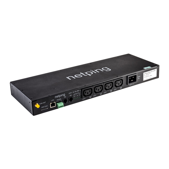
[ENG] NetPing 8/PWR-220 v4/SMS, User guide -[8PWR] Sockets and Indication Elements Power Supply Channels On a front panel there is the second group of power supply channels, with numbers of channels 5 – 8. On a back panel there is the first group of power supply channels, with numbers of channels 1 -4. -
Page 11: Sensor Plugin Terminals
[ENG] NetPing 8/PWR-220 v4/SMS, User guide -[8PWR] Sockets and Indication Elements On a back panel there is a power supply input A. Sensor Plugin Terminals On a back panel there is a terminal block for sensors plugin. Assignment of the terminals is from left to right: IO1, IO2, IO3, IO4, SC, SD, +5V, GND. - Page 12 [ENG] NetPing 8/PWR-220 v4/SMS, User guide -[8PWR] Sockets and Indication Elements [8PWR] Sockets and Indication Elements – ...
-
Page 13: [8Pwr] Power Supply Channels Management
[8PWR] Power Supply Channels Management Channels Management A NetPing 8/PWRv3/SMS device has eight independent power supply channels. Each channel is managed by a normally closed relay. A relay and tracks have a big power capacity reserve, which provides a high resistance of a device to overloading. -
Page 14: [8Pwr] Setting Parameters To Default Values (To The Factory Settings)
[ENG] NetPing 8/PWR-220 v4/SMS, User guide -[8PWR] Setting Parameters to Default Values (to the Factory Settings) [8PWR] Setting Parameters to Default Values (to the Factory Settings) Resetting parameters to the factory settings is necessary in the following cases : • A loss of a login and/or password to a web interface of a device;... -
Page 15: [8Pwr] Using Io Lines For External Devices Management (In An Output Mode)
[ENG] NetPing 8/PWR-220 v4/SMS, User guide -[8PWR] Using IO Lines for External Devices Management (in an Output Mode) [8PWR] Using IO Lines for External Devices Management (in an Output Mode) Input-Output (IO) lines of a device can be used for an input work as well as in an output mode for managing external devices. -
Page 16: Equivalent Сircuit
[ENG] NetPing 8/PWR-220 v4/SMS, User guide -[8PWR] Using IO Lines for External Devices Management (in an Output Mode) Equivalent Сircuit [8PWR] Using IO Lines for External Devices Management (in an Output Mode) – ... -
Page 17: [8Pwr] Sensors Plugin
[ENG] NetPing 8/PWR-220 v4/SMS, User guide -[8PWR] Sensors Plugin [8PWR] Sensors Plugin Sensors 1-Wire Sensors 1-Wire (Temperature 1-wire, (THS), 2m and Humidity sensor 1-wire) connected to the connectors 1W plugs RJ12, allowed to use extension cords or splitters. Maximum cable length 1-Wire network is limited to 50 meters. -
Page 18: Supply Voltage Sensor
[ENG] NetPing 8/PWR-220 v4/SMS, User guide -[8PWR] Sensors Plugin Important! Sensors of a dry contact type, a supply voltage sensor, a leakage sensor, and others are plugged to IO lines of a device. You can plug any four sensors out of this set. -
Page 19: Plugging Netping Ac/Din Sockets
When plugging a socket to a device, all wires are used except for a brown one. There is a need to switch an IO line, to which a NetPing AC/DIN socket is connected, to the status "output". When a status of an IO line is logic 0, the socket will have 220V, and a load will be turned on. -
Page 20: [8Pwr] Shipping Kit
[ENG] NetPing 8/PWR-220 v4/SMS, User guide -[8PWR] Shipping Kit [8PWR] Shipping Kit A shipping kit is shown at the picture: A shipping kit includes: • A device NetPing 8/PWRv3/SMS; • An antenna; • A user guide; • A packing box;... -
Page 21: [8Pwr] Operating And Storage Conditions
[ENG] NetPing 8/PWR-220 v4/SMS, User guide -[8PWR] Operating and Storage Conditions [8PWR] Operating and Storage Conditions A device is designed for continuous round the clock operation indoors. In operating conditions of use, a device is resistant to an environment with temperature in a range of 0°С - +40°С (32 – 104 degrees Fahrenheit) and relative humidity in a range of 5% - 95 % at 25°С... -
Page 22: [8Pwr] Warranty
[ENG] NetPing 8/PWR-220 v4/SMS, User guide -[8PWR] Warranty [8PWR] Warranty The manufacturer guarantees normal operation of the product within 24 months from the date specified on the warranty sticker if a buyer follows operating and storage conditions. Manufacturer warranty applies only to failure of a device which occurred because of defects in manufacturing process of products and components used.
Need help?
Do you have a question about the 8/PWR-220 v4/SMS and is the answer not in the manual?
Questions and answers