
Related Manuals for Rohde & Schwarz CTS60


Summary of Contents for Rohde & Schwarz CTS60
- Page 1 Test and Measurement Division Operating Manual Digital Radio Tester DECT R&S CTS60 1094.0006.60 Printed in Germany 1094.3411.12-06-...
- Page 2 Dear Customer, R&S® is a registered trademark of Rohde & Schwarz GmbH & Co. KG. Trade names are trademarks of the owners. 1094.3411.12-07-...
-
Page 3: Table Of Contents
CTS60 Contents Contents Data Sheet Safety Instructions EC Certificate of Conformity Certificate of quality List of R&S Representatives Page 1 Introduction ..........................1.1 1.1 Autotest Applications .......................1.1 rview........................1.1 Configurable Test Steps in Autotest ................1.1 1.2 Manual Test Applications ......................1.1 2 Preparation for Use ........................2.1... - Page 4 Contents CTS60 4 Getting Started With Manual Test ..................4.1 4.1 Overview ............................4.1 4.2 Testing a Fixed Part........................4.2 4.3 Testing a Portable Part......................4.5 4.4 Transmitter Measurements......................4.8 4.5 Receiver Measurements......................4.12 5 RF connection ..........................5.1 5.1 RF Connection of the Device Under Test Using an Antenna Coupler.........5.1 6 Detailed Description of the Menus ..................6.1...
- Page 5 CTS60 Contents 6.6 Manual Test Menus.........................6.17 6.6.1 Synchronisation Menu (GAP Mode Fixed Part Tests) ..........6.17 6.6.1.1 Subscription of the Fixed Part ..............6.19 6.6.1.2 Subscribing the Fixed Part................6.20 6.6.2 Synchronisation Menu (GAP Mode Portable Part Tests)..........6.21 6.6.2.1 Subscription of the Portable Part ..............6.22 6.6.2.2...
- Page 6 Contents CTS60 7 Autotest Printed Reports ......................7.1 7.1 Overview ............................7.1 7.2 Header and Footer ........................7.2 7.2.1 First Page Header (Fixed Part) ..................7.2 7.2.2 First Page Header (Portable Part) .................7.3 7.2.3 Standard Header......................7.4 7.2.4 Test Result Footer ......................7.4 7.3 Measurement Results.......................7.5 7.3.1...
- Page 7 CTS60 Contents 8.8 Status Reporting System .......................8.17 8.8.1 Structure of an SCPI Status Register ................8.17 8.8.2 Overview of the Status Registers.................8.19 8.8.3 Description of the Status Registers................8.20 8.8.3.1 Status Byte (STB) and Service Request Enable Register (SRE) ....8.20 8.8.3.2 Event-Status-Reg. (ESR) and Event-Status-Enable-Reg. (ESE) ....8.21 8.8.4...
- Page 8 Contents CTS60 Annex A: Interfaces Annex B: List of Error Messages Annex C: Remote Control (List of Commands) Index 1094.3411.12...
- Page 9 Supplement to Data Sheet CTS (PD0757.2509.22) Specifications supplement: Restricted output level range of DECT signal generator at connector RF IN/OUT, when RF IN2 DECT is active: DECT signal generator Output level RF IN/OUT -100 dBm to -40 dBm (-80 dBm to -40 dBm if RF IN2 DECT is active) RF OUT2 DECT -40 dBm to 0 dBm (-20 dBm to 0 dBm if RF IN2 DECT is active)
- Page 11 Supplement to Data Sheet CTS (PD757.2509.22) Page 12: GSM signal generator Output level RF OUT2 GSM with 0 dB ext. attenuation -20 dBm to -75 dBm Page 13: Analog DECT ADPCM interface (cancelled) General data Operating temperature range +5°C to +45°C PD757.2509.22...
- Page 13 Before putting the product into operation for the first time, make sure to read the following S a f e t y I n s t r u c t i o n s Rohde & Schwarz makes every effort to keep the safety standard of its products up to date and to offer its customers the highest possible degree of safety.
- Page 14 Safety Instructions Observing the safety instructions will help prevent personal injury or damage of any kind caused by dangerous situations. Therefore, carefully read through and adhere to the following safety instructions before putting the product into operation. It is also absolutely essential to observe the additional safety instructions on personal safety that appear in other parts of the documentation.
- Page 15 Safety Instructions 4. If products/components are mechanically 10. Intentionally breaking the protective earth and/or thermically processed in a manner connection either in the feed line or in the that goes beyond their intended use, product itself is not permitted. Doing so can hazardous substances (heavy-metal dust result in the danger of an electric shock such as lead, beryllium, nickel) may be...
- Page 16 Safety Instructions 19. If a product is to be permanently installed, matching Rohde & Schwarz type (see the connection between the PE terminal on spare parts list). Batteries and storage site and the product's PE conductor must batteries are hazardous waste. Dispose of be made first before any other connection them only in specially marked containers.
- Page 17 Por favor lea imprescindiblemente antes de la primera puesta en funcionamiento las siguientes informaciones de seguridad Informaciones de seguridad Es el principio de Rohde & Schwarz de tener a sus productos siempre al día con los estandards de seguridad y de ofrecer a sus clientes el máximo grado de seguridad. Nuestros productos y todos los equipos adicionales son siempre fabricados y examinados según las normas de seguridad vigentes.
- Page 18 Informaciones de seguridad Tener en cuenta las informaciones de seguridad sirve para tratar de evitar daños y peligros de toda clase. Es necesario de que se lean las siguientes informaciones de seguridad concienzudamente y se tengan en cuenta debidamente antes de la puesta en funcionamiento del producto. También deberán ser tenidas en cuenta las informaciones para la protección de personas que encontrarán en otro capítulo de esta documentación y que también son obligatorias de seguir.
- Page 19 Informaciones de seguridad seguridad (control a primera vista, control de peligro a causa de la radiación conductor protector, medición de resistencia electromagnética. El empresario está de aislamiento, medición de medición de la comprometido a valorar y señalar areas de corriente conductora, control trabajo en las que se corra un riesgo de...
- Page 20 Informaciones de seguridad 12. No utilice nunca el producto si está dañado el 20. En caso de que los productos que son cable eléctrico. Asegure a través de las instalados fijamente en un lugar sean sin medidas de protección y de instalación protector implementado, autointerruptor o adecuadas de que el cable de eléctrico no similares objetos de protección, deberá...
- Page 21 Informaciones de seguridad 27. Baterías y acumuladores no deben de ser 31. Las asas instaladas en los productos sirven expuestos a temperaturas altas o al fuego. solamente de ayuda para el manejo que Guardar baterías y acumuladores fuera del solamente está previsto para personas. Por alcance de los niños.
- Page 23 Certificate No.: 98080 This is to certify that: Equipment type Order No. Designation CTS60 1094.0006.60 Digital Radio Tester complies with the provisions of the Directive of the Council of the European Union on the approximation of the laws of the Member States...
-
Page 25: Introduction
TFT colour display which helps to make the CTS60 easy to use. There are two types of tests available on the CTS60; the first is a configurable automatic function test called Autotest, the second is a detailed service test called Manual Test. -
Page 27: Preparation For Use
A rechargeable battery is installed in the CTS60 which allows storage of important instrument parameters when the instrument is switched off. This battery is automatically charged during operation of the instrument. For the battery to be sufficiently charged, the CTS60 should not remain switched off for longer than three months. -
Page 28: Explanation Of Front And Rear View
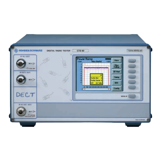
Preparation for Use CTS60 Explanation of Front and Rear View This page shows the front and rear view of the instrument, with short explanations on the controls and connectors. TFT Display DIGITAL RADIO TESTER CTS 60 1094.0006.60 RF IN 2 DECT... - Page 29 CTS60 Preparation for Use Instrument with wide-range voltage input Service connector Fan of power supply unit (controlled) (e. g. for ext. monitor) MONITOR Power switch on/off 100 ... 240 V / 160 VA 50 ... 60 Hz (uncontrolled) Audio Input (DECT)
-
Page 30: 2.2 Commissioning
Connecting the Instrument to the AC Supply Check the position of the voltage selector and set it to the local AC supply voltage if necessary. Plug the supplied power cable into the rear power connector and connect the CTS60 to the power supply. -
Page 31: Ensuring Electromagnetic Compliance (Emc)
Only appropriate shielded signal and control cables (e.g. RF connecting cables) should be used. 2.2.4 Switching on the Instrument The CTS60 is switched on by means of the power switch at the rear. 1094.0006.60... -
Page 32: Options List
Preparation for Use CTS60 2.2.5 Options List After the instrument is switched on a start up screen is displayed while the instruments loads stored parameters and checks which options are installed. After a short time the options screen is displayed (see below). -
Page 33: Getting Started With Autotest
In Autotest mode the CTS60 is easy and convenient to operate thanks to its clear menu structure. If this is your first encounter with CTS60 in Autotest mode, this chapter will give you a quick survey of configuring and running an automatic test. -
Page 34: Configuring An Autotest
Getting Started With Autotest CTS60 Configuring an autotest Step 1 When the CTS60 is switched on the Home Menu shown opposite appears after a few seconds. The instrument is now ready for testing. Use the "Test Mode" key to toggle between the Manual Test, and Autotest Test modes (must be set to Autotest). - Page 35 CTS60 Getting Started With Autotest Step 3 The autotest edit menu is now displayed. This menu will enable you to configure a particular test. Press "Edit Name" and enter a name for this test (note that the test number is not editable).
-
Page 36: Running A Fixed Part Test
(for information on how to activate the service mode of the fixed part please contact the manufacturer). When the CTS60 is switched on the Home Menu shown opposite appears. The instrument is now ready for testing. Use the "Test Mode"... - Page 37 CTS60 Getting Started With Autotest The select test menu is now displayed. Press the Test ↑ and Test ↓ keys to move up and down the list of tests until you have selected the test you wish to run. Press "Menu up" to accept the selection.
- Page 38 Getting Started With Autotest CTS60 Step 4 To start the test press "Start" on the autotest start menu. Autotest Start Menu While the test is running the test results are displayed in a scrolling window. The "Action/Parameter" column displays the number of...
- Page 39 CTS60 Getting Started With Autotest Step 5 Once the test has completed or been aborted the autotest results menu will be displayed. This displays the results of the test as they were displayed while the test was running. The overall result of the test is displayed at the bottom.
-
Page 40: Running A Portable Part Test
When the CTS60 is switched on the Home Menu shown opposite appears. The instrument is now ready for testing. Use the "Test Mode" key to toggle between the Manual Test, and Autotest Test modes (must be set to Autotest). - Page 41 CTS60 Getting Started With Autotest The select test menu is now displayed. Press the Test ↑ and Test ↓ keys to move up and down the list of tests until you have selected the test you wish to run. Press "Menu up" to accept the selection.
- Page 42 Getting Started With Autotest CTS60 Step 4 To start the test press "Start" on the autotest start menu. Autotest Start Menu While the test is running the test results are displayed in a scrolling window. The "Action/Parameter" column displays the number of...
- Page 43 CTS60 Getting Started With Autotest Step 5 Once the test has completed or been aborted the autotest results menu will be displayed. This displays the results of the test as they were displayed while the test was running. The overall result of the test is displayed at the bottom.
-
Page 44: Notes On Configuring An Autotest
• Make sure to select a level sufficiently high to match the selected coupling. • If a test step is configured as pause the CTS60 will not continue until the "CONT" key is pressed or a timeout period is reached. -
Page 45: Getting Started With Manual Test
In Manual Test mode the user selects the required test by selecting an appropriate measurement menu. If this is your first encounter with CTS60 in Manual Test mode, this chapter will give you a quick survey of tests performed on DECT fixed and portable parts. You will be guided step by step through the Manual Test menus. -
Page 46: Testing A Fixed Part
(for information on how to activate the service mode of the fixed part please contact the manufacturer). When the CTS60 is switched on the Home Menu shown opposite appears after a few seconds. The instrument is now ready for testing. - Page 47 CTS60 Getting Started With Manual Test As soon as the CTS60 has successfully synchronised with the fixed part the "Synchroni- sing" message will disappear. The text "Press "Connect" to connect to FP" appears in a green box at the bottom of the screen.
- Page 48 Getting Started With Manual Test CTS60 Step 4 Return to the Synchronisation menu and wait for the CTS60 to Synchronise with the fixed part. Press "Connect" on the Synchro- nisation menu to set up the connection. Synchronisation Menu The display will change to the Connection Established Menu.
-
Page 49: Testing A Portable Part
When the CTS60 is switched on the Home Menu shown opposite appears after a few seconds. The instrument is now ready for testing. Use the "Test Mode" key... - Page 50 "Config" on the Synchro- nisation menu. Here the traffic and dummy slots should be configured to ensure that they are not the same. The RF transmit level of the CTS60 should configured appropriate value. desired carrier offset if required.
- Page 51 Getting Started With Manual Test Step 5 The connection can be released at any point by pressing the "Bearer Release" key or "Menu up" on the Connection Estab- lished menu. The CTS60 will then return to the Synchronisation menu. Connection Established Menu 1094.0006.60...
-
Page 52: Transmitter Measurements
Transmitter Measurements In the Connection Established Menu the traffic slot and carrier of the current connection, and the transmit RF level of the CTS60 are displayed. If a portable part is being tested its PMID will also be displayed here. - Page 53 CTS60 Getting Started With Manual Test After selecting the power ramp by pressing the "Power" key the Power Ramp screen will be displayed. Here the DUT’s burst is dis- played. Using the "View" key different views of the ramp can be selec- ted.
- Page 54 Getting Started With Manual Test CTS60 After selecting RF modulation by pressing the "RF Mod" key the RF Modulation menu will be displayed. Here the modulation of the DUT’s RF burst is displayed. Using the "View" key different views of the modulation graph can be selected.
- Page 55 CTS60 Getting Started With Manual Test When selected portable part the menu opposite is displayed. This displays the maximum positive and negative jitter measurements, and the maximum and minimum packet delay measurements. If any of these measurements are out of tolerance they are displayed in red.
-
Page 56: Receiver Measurements
It is also possible to configure the RF transmit level of the CTS60 on this menu to assess its effect on the frame and bit error rates. Current and longterm measure- BER Menu ments of the frame and bit error rate are displayed here. -
Page 57: Rf Connection
The output attenuation value is used when setting the RF transmit level of the CTS60. The RF level configured on the CTS60 is the actual power level received by the DUT allowing for the attenuation. -
Page 59: Detailed Description Of The Menus
CTS60 Description of the Menus Detailed Description of the Menus Menu Structure 6.1.1 Menu Structure Overview The entire menu structure is divided into four sections (see menu structure graph): 1. Menus seen immediately after power on, that is the Logo screen, the Available Options Menu and the Home Menu. -
Page 61: Field Editing
Description of the Menus Field Editing The are many values on the CTS60 which require configuration. Most configuration menus have several variable fields. These will use the multi-field editing approach, described below, to move between the different fields on the menu and configure their values. Some other menus that have a single field which is configurable. -
Page 62: Single Field Editing
Description of the Menus CTS60 6.2.2 Single Field Editing The above menu is an example of single field editing. The field which is active for editing is shown by the edit symbol ( ). The field is activated for editing by pressing the key next to it (in the above example "Edit RFPI"). -
Page 63: Home Menu
CTS60 Description of the Menus Home Menu This is the Home Menu of the system. It is displayed after the system has started up and when either the Manual test, Autotest or Configuration menus are exited. From the Home Menu each part of the system can be reached (see menu structure graph). -
Page 64: Selecting And Configuring Types
CTS60 Selecting and Configuring Types The CTS60 supports the definition of sets of fixed and portable part types. These can be configured with values specific to a particular DUT. The type can then be selected before performing a particular test. -
Page 65: Config Fp Or Pp Types Menu
CTS60 Description of the Menus 6.4.2 Config FP or PP Types Menu These menus allow the list of fixed or portable to be configured. It enables the insertion, deletion and editing of type definitions. All types in the list are displayed in alphabetical order. Access to this menu is only available by pressing the config key on the home menu and then selecting config FP or PP Type from the list of items available. -
Page 66: Edit Fp Types Menu
CTS60 and will be used when calculating power levels. Any RF transmit level configured on the CTS60 will represent the actual level received at the fixed part after the output attenuation has been allowed for. This means that the RF level actually emitted by the CTS60 is higher than the displayed value by the magnitude of the output attenuation. -
Page 67: Edit Pp Types Menu
"Yes" do not remove dummy bearer after connection is established. The fields "Q0", "Q3", and "Q6" define values for the MAC layer Q-packets transmitted by the CTS60 when in PP test mode. Each is defined as a series of hexadecimal values which correspond to a Q- packet message, it should be noted however that not all of these are transmitted to the signalling. -
Page 68: Autotest Menus
Pressing this key controls the type of synchronisation used during an autotest. If Accept RFPI is set to No the CTS60 will only synchronise to a fixed part with an RFPI the same as the value entered using "Edit RFPI". If Accept RFPI is set to Yes the CTS60 does not use the entered RFPI value to synchronise. -
Page 69: Autotest Start Menu (Portable Part Tests)
CTS60 Description of the Menus 6.5.2 Autotest Start Menu (Portable Part Tests) This menu is displayed after the Autotest test mode has been activated from the home menu and the DUT selected is "Portable Part". Start Pressing this key starts the autotest. -
Page 70: Autotest Select Test Menu
Description of the Menus CTS60 6.5.3 Autotest Select Test Menu This menu is used to select one of the 10 fixed part or 10 portable part tests which can be configured. The set of tests which can be configured depends on the currently selected DUT. -
Page 71: Autotest Edit Test Menu
CTS60 Description of the Menus 6.5.4 Autotest Edit Test Menu This menu is used to configure a selected test. Each test can contain up to 50 test steps each of which can be configured with a variety of different actions. -
Page 72: Autotest Select Action Menu
Description of the Menus CTS60 6.5.5 Autotest Select Action Menu This menu is used to select an action for the currently selected test step. The available actions are: • Free - no action defined (default value for new test steps). -
Page 73: Autotest Running Menu
CTS60 Description of the Menus 6.5.6 Autotest Running Menu In this menu the Autotest is running. This screen indicates the results of each step of the Autotest. In the Action/Parameter column the menu displays the test step number, and the action currently being performed, and a list of the measured parameters for each action. -
Page 74: Autotest Results Menu
Description of the Menus CTS60 6.5.7 Autotest Results Menu When the measurement sequence has finished or has been aborted the Autotest Results menu is displayed (as shown above). From this menu it is possible to return to the Autotest Start menu, scroll up and down through the test results or to print a test report. -
Page 75: Manual Test Menus
• the CTS60 transmit level in dBm. Connect By pressing this key the CTS60 will attempt to set up a connection with the fixed part with a PARK the same as the configured PARK. Different to non-GAP mode: the fixed part doesn’t need to be in test mode. - Page 76 Description of the Menus CTS60 Edit PARK (Private Access Rights Key) By pressing this key the configured PARK value can be edited. Accept PARK Pressing this key copies the value of the detected PARK to the configured PARK. Subscribe Pressing this softkey displays a further menu where subscription of the fixed part can be initiated if required.
-
Page 77: Subscription Of The Fixed Part
CTS60 Description of the Menus 6.6.1.1 Subscription of the Fixed Part After pressing the “Subscribe” softkey as described in section 6.6.1, the following menu will be displayed. The following softkeys are present. Start Subscr Press this softkey to start the subscription process. The DUT, in this case the fixed part, must already be in subscribing mode and ready to be subscribed. -
Page 78: Subscribing The Fixed Part
Description of the Menus CTS60 6.6.1.2 Subscribing the Fixed Part After the subscription process has been initiated, then the following menu will be displayed. It is at this point where the fixed part DUT must already have been configured to accept subscription and must be waiting for this event to occur. -
Page 79: Synchronisation Menu (Gap Mode Portable Part Tests)
• the CTS60 transmit level in dBm. Connect By pressing this key the CTS60 will make a call to the portable part. If you take the portable part off hook the CTS60 will attempt to set up a connection. Note: 1. You can setup a connection only by taking the portable part off hook. -
Page 80: Subscription Of The Portable Part
Description of the Menus CTS60 6.6.2.1 Subscription of the Portable Part After pressing the “Subscribe” softkey as described in section 6.6.2, the following menu will be displayed. The following softkeys are present. Start Subscr Press this softkey to start the subscription process. The DUT, in this case the portable part, must already be in subscribing mode and ready to be subscribed. -
Page 81: Subscribing The Portable Part
CTS60 Description of the Menus 6.6.2.2 Subscribing the Portable Part After the subscription process has been initiated, then the following menu will be displayed. It is at this point where the portable part DUT must already have been configured to accept subscription and must be waiting for this event to occur. -
Page 82: Connection Established Menu (Fixed Part Tests)
At any time the connection can be cleared by a bearer release initiated by the CTS60 or as a result of a loss of the traffic connection with the fixed part (usually due to poor signal quality or removal of power from the fixed part). - Page 83 CTS60 Description of the Menus RF Mod This key allows the RF modulation measurement to be selected. Timing This key allows the timing measurement to be selected. This key allows the bit error rate measurement to be selected. Number of Bursts Pressing this key allows the number of bursts measurements are taken over to be configured.
-
Page 84: Connection Established Menu (Portable Part Tests)
At any time the connection can be cleared by a bearer release initiated by the CTS60 or as a result of a loss of the traffic connection with the fixed part (usually due to poor signal quality or removal of power from the fixed part). - Page 85 CTS60 Description of the Menus RF Mod This key allows the RF modulation measurement to be selected. Timing This key allows the timing measurement to be selected. This key allows the bit error rate measurement to be selected. Number of Bursts Pressing this key allows the number of bursts measurements are taken over to be configured.
-
Page 86: Power Ramp Menu
Description of the Menus CTS60 6.6.5 Power Ramp Menu In this screen the Power Ramp of the signal transmitted by the DUT is displayed as a function of time. The tolerance template for the power ramp is also displayed. This must not be exceeded by the ramp. - Page 87 CTS60 Description of the Menus This key allows the bit error rate measurement to be selected. Config Press this key to access the configuration menu for the power ramp. Stop/Cont Press this key to stop or continue the power ramp measurement. The text on the key will be "Stop" or "Cont"...
-
Page 88: Rf Modulation Menu
6.6.6 RF Modulation Menu In this menu, the modulated signal received by the CTS60 from the DUT is displayed as a function of time. In addition to this the measured values of frequency offset, maximum positive and negative B-field modulation, frequency drift, and an X=Z field comparison are displayed. If any of these measurements exceed their configured tolerance values then they are displayed in red. - Page 89 CTS60 Description of the Menus This key allows the bit error rate measurement to be selected. Config Press this key to access the configuration menu for the RF modulation measurement. Menu up Press this key to return to the previous menu.
-
Page 90: Timing Menu (Fixed Part)
• Timing accuracy, is the accuracy of the time period of the configured number of bursts with respect to the timer on the CTS60. This measurement is displayed with both a value and an indicator bar. • Maximum positive jitter is the maximum positive time interval between two successive bursts minus the average time period. -
Page 91: Timing Menu (Portable Part)
• Maximum negative jitter is the maximum negative time interval between two successive bursts minus the average time period. • Maximum packet delay is the maximum time interval between the CTS60 bursts (transmitting as a fixed part) and bursts from the portable part under test minus 5ms (half a frame). -
Page 92: Bit Error Rate Menu
This key allows the timing measurement to be selected. RF Level By pressing this the CTS60 transmit level for BER measurements can be configured. The RF level value will be sent to the hardware as it is changed. This enables the effects on the BER and FER measurements to be monitored in real-time. -
Page 93: Auto And Manual Test Configuration Menus
CTS60, without modification. This is a prerequisite for bit error rate and some modulation measurements. • Normal: in this mode no loopback of the data is performed. • Echo: audio signals sent to the CTS60 by the fixed part are delayed by one second and sent back to the fixed part. Default Press this key to reset all values to factory default values. -
Page 94: Config Synchronisation Menu (Gap Mode Portable Part)
The RF level value is the transmit power of the CTS60. It can be configured to any value from -100dBm to -40dBm if connector IN1/OUT1 is used, or -40dBm to 0dBm if connectors IN1 and OUT2 are used, or -20dBm to 0dBm if connectors IN2 and OUT2 are used. - Page 95 CTS60 Description of the Menus Channel / Frequency Table The following table shows the allocation of DECT channel numbers to frequencies as a function of the channel offset. For a channel offset of -17 for example, the DECT channel 0 corresponds to a frequency of 1926.720 MHz and channel 9 to a frequency of 1911.168 MHz.
- Page 96 Description of the Menus CTS60 Channel -3.5 1903.392 1901.664 1899.936 1898.208 1896.480 1894.752 1893.024 1891.296 1889.568 1887.840 Offset -3.0 1902.528 1900.800 1899.072 1897.344 1895.616 1893.888 1892.160 1890.432 1888.704 1886.976 -2.5 1901.664 1899.936 1898.208 1896.480 1894.752 1893.024 1891.296 1889.568 1887.840 1886.112 -2.0 1900.800 1899.072 1897.344 1895.616 1893.888 1892.160 1890.432 1888.704 1886.976 1885.248...
-
Page 97: Config Synchronisation Menu (Portable Part For Autotest)
When the sync. type is manual the user is prompted to press the continue key when the portable part has synchronised. When the sync. type is automatic the CTS60 will wait the number of seconds defined by sync. time before setting up the connection. Time values can be configured from 0 to 10 seconds. -
Page 98: Config Power Ramp Menu
Description of the Menus CTS60 6.7.4 Config Power Ramp Menu In this menu the configuration for the power ramp measurement is defined. The template is shown at the top of the screen. The various ranges of the template are identified with the letters B to F. The tolerance values for these ranges are shown below the template. -
Page 99: Config Rf Modulation Menu (Selectable Frequency Drift Units)
CTS60 Description of the Menus 6.7.5 Config RF Modulation Menu (Selectable frequency drift units) This menu is used to define the configuration for the RF modulation measurement. The first field defines the data type transmitted to the DUT. The following types can be selected: •... -
Page 100: Config Timing Menu (Fixed Part)
Description of the Menus CTS60 6.7.6 Config Timing Menu (Fixed Part) This menu is used to define the configuration for the timing measurement of fixed parts. The number of bursts (2 to 1000) over which the timing values are averaged can be configured in this menu. -
Page 101: Config Timing Menu (Portable Part)
CTS60 Description of the Menus 6.7.7 Config Timing Menu (Portable Part) This menu is used to define the configuration for the timing measurement of portable parts. The number of bursts (2 to 1000) over which the timing values are averaged can be configured in this menu. -
Page 102: Config Ber (Manual Test)
Description of the Menus CTS60 6.7.8 Config BER (Manual Test) This menu is used to define the tolerances for the bit error rate measurement in manual test. In this menu the number of bursts in the measurement window can be configured. This value can be between 1 and 30 000 000. -
Page 103: Config Ber (Autotest)
The default setting for the SW Decoding is OFF. In this menu the RF transmit level of the CTS60 during this test step can also be configured. Default Press this key to reset all values to factory default values. -
Page 104: Config Goto (Autotest Only)
Description of the Menus CTS60 6.7.10 Config Goto (Autotest only) In this menu an autotest conditional loop can be configured. Line number allows the test step to jump to to be configured. The no. of Loops (N) field is used by the N times condition to define the number of loops to perform. -
Page 105: General Configuration Menus
6.8.1 Config - Select This menu is the selection menu for configuring the CTS60; nearly all of the configuration menus available from other parts of the CTS60 can also be accessed from here. The configuration menus listed can be selected by highlighting them and then pressing the "Select" key. The available options can be displayed by pressing the "Options"... -
Page 106: Config Date/Time
Description of the Menus CTS60 6.8.2 Config Date/Time With this menu the date and time of the system can be changed. Menu up (hardkey) Pressing this key stores the configured date and time and returns to the config select menu. -
Page 107: Config Language
CTS60 Description of the Menus 6.8.3 Config Language With this menu the language of the system can be selected: all text shown in all menus is changed according to the selected language. Language , Language These keys move up and down the list of languages. The currently selected language is highlighted with a horizontal bar. -
Page 108: Config Password
Description of the Menus CTS60 6.8.4 Config Password In this menu the password protection of the configuration menus can be activated and deactivated. Also by pressing the "Change Password" key a new password can be entered. Password Press this key to toggle the password protection on or off. If a password has already been supplied then this must be entered before this setting can be changed. -
Page 109: Enter Password
CTS60 Description of the Menus 6.8.5 Enter Password The menu on the left is displayed when the "Change Password" key is pressed on the config password menu. The password consists of six digits entered by pressing one of the softkeys "1" to "6". When these digits are entered they are not displayed on the screen;... -
Page 110: Com Port
Description of the Menus CTS60 6.8.6 Com Port This menu allows the serial port to be configured for remote control. It also allows the type of display used for remote control to be configured. The standard RS232 settings which can be configured on this menu are the following: •... -
Page 111: Comment Menu
CTS60 Description of the Menus 6.8.7 Comment Menu In this menu a comment can be entered which is printed in the first line of the comment field of the Autotest report. An alphanumeric sequence of max. 56 characters can be entered. -
Page 112: Config Keyboard Menu
CTS60 6.8.8 Config Keyboard Menu This menu is used to define which country specific keyboard is been connected to the CTS60. Keyboard , Keyboard These keys move up and down the list of country specific keyboards. The currently selected keyboard is highlighted with a horizontal bar. -
Page 113: Config - Save
Description of the Menus 6.8.9 Config - Save This menu is used to save the current configuration of the instrument. Note that for the CTS60 this does not apply to autotest. 1, 2, 3, 4, 5 Select one of the five possible configurations which can be saved. -
Page 114: Config - Load
Config - Load This menu is used to load a previously save instrument configuration. It can also be used to load up the factory settings. Note that for the CTS60 this does not apply to autotest. 1, 2, 3, 4, 5 Load one of the five saved configurations. -
Page 115: Autotest Printed Reports
CTS60 Autotest Printed Reports Autotest Printed Reports Overview From the autotest results menu it is possible to print out a report of the displayed results. The following sections describe each of the different parts of the report in detail. The header at the top of the first page describes details of the test and its configuration. On subsequent pages a smaller header is displayed. -
Page 116: Header And Footer
____________________________________________________________________ DECT FP Test Report 01: Standard Test Date: 11/03/1998 Time: 11:24 AM Page: 1 of 10 Test Station: CTS60 Rohde & Schwarz Comment: This test should be successful |____________________________________________________________________| FP Type: A DECT fixed part RFPI: 0001234567 Packet Type:... -
Page 117: First Page Header (Portable Part)
____________________________________________________________________ DECT PP Test Report: 01: Standard Test Date: 11/03/1998 Time: 11:24 AM Page: 1 of 10 Test Station: CTS60 Rohde & Schwarz Comment: This test should be successful |____________________________________________________________________| PP Type: A DECT portable part RFPI: 0001234567 Packet Type:... -
Page 118: Standard Header
Autotest Printed Reports CTS60 7.2.3 Standard Header ____________________________________________________________________ DECT PP Test Report: 01: Standard Test Date: 11/03/1998 Time: 11:24 AM Page: 2 of 10 |____________________________________________________________________| This header is printed at the top of the second and subsequent pages of every portable and fixed part autotest printed report. -
Page 119: Measurement Results
The first line details the test step number in brackets followed by Setup Connection the action which was executed. RF Level The configured CTS60 transmit level for this test step in dBm. Carrier No. Offset The carrier number offset configured for this test step. -
Page 120: Setup Connection (Portable Part)
The first line details the test step number in brackets followed by Setup Connection the action which was executed. RF Level The configured CTS60 transmit level for this test step in dBm. Carrier No. Offset The carrier number offset configured for this test step. -
Page 121: Power Ramp
CTS60 Autotest Printed Reports 7.3.3 Power Ramp ____________________________________________________________________ | (02) Power Ramp (Bursts = 4): Value Limits Result | Min. Max. (dBm) 22.0 20.0 25.0 OK | B (abs) (uW) PASS OK | C (rel) (dB) PASS OK | D (rel) -
Page 122: Timing (Fixed Part)
Autotest Printed Reports CTS60 7.3.4 Timing (Fixed Part) ____________________________________________________________________ | (03) Timing (Bursts = 32): Value Limits Result | Min. Max. Timing Accuracy (ppm) 2.24 OK | Max. Pos. Jitter (us) 0.03 OK | Max. Neg. Jitter (us) -0.84 -1.0... -
Page 123: Timing (Portable Part)
CTS60 Autotest Printed Reports 7.3.5 Timing (Portable Part) ____________________________________________________________________ | (03) Timing (Bursts = 32): Value Limits Result | Min. Max. Max. Pos. Jitter (us) 0.03 OK | Max. Neg. Jitter (us) -0.84 -1.0 OK | Max. Packet Delay (us) 0.53... -
Page 124: Rf Modulation
Autotest Printed Reports CTS60 7.3.6 RF Modulation ____________________________________________________________________ | (04) RF Modulation (Bursts = 100, Data Type = 01010101): Value Limits Result | Min. Max. Freq. Offset (kHz) OK | Max. Pos. B-field (kHz) +349 OK | Max. Neg. B-field (kHz) –351... -
Page 125: Bit Error Rate
CTS60 Autotest Printed Reports 7.3.7 Bit Error Rate ____________________________________________________________________ | (05) Bit Error Rate (Bursts = 30000000, RF Level = -100.0 dBm): Value Limits Result | Min. Max. Longterm BER (ppm) 5649 1000 FAIL | Longterm FER (ppm) 9452 10000... -
Page 127: Remote Control
CTS60 Remote Control Remote Control Introduction The instrument is equipped with a serial interface (RS 232-C). The connector is located at the rear of the instrument and permits to connect a controller for remote control. The instrument supports the SCPI version 1992.0 (Standard Commands for Programmable Instruments). -
Page 128: Switchover To Remote Control
Remote Control CTS60 Switchover to Remote Control On power-on, the instrument is always in the manual operating state ("LOCAL" state) and can be operated via the front panel. It is switched to remote control ("REMOTE" state) as soon as it receives a command from a controller. -
Page 129: Structure And Syntax Of The Device Messages
CTS60 Remote Control Structure and Syntax of the Device Messages 8.5.1 SCPI Introduction SCPI (Standard Commands for Programmable Instruments) describes a standard command set for programming instruments, irrespective of the type of instrument or manufacturer. The goal of the SCPI consortium is to standardize the device-specific commands to a large extent. - Page 130 Remote Control CTS60 SOURce POWer POLarity MODE EXTernal STATe INTernal POLarity COUPling Fig. 8-1 Tree structure of the SCPI command systems using the SOURce system by way of example Some key words occur in several levels within one command system. Their effect depends on the structure of the command, that is to say, at which position in the header of a command they are inserted.
-
Page 131: Structure Of A Command Line
CTS60 Remote Control Long and short form: The key words feature a long form and a short form. Either the short form or the long form can be entered, other abbreviations are not permissible. Example: STATus:QUEStionable:ENABle 1= STAT:QUES:ENAB 1 Note: The short form is marked by upper-case letters, the long form corresponds to the complete word. - Page 132 Remote Control CTS60 Example: SOURce:FM:MODE LOCKed;:SOURce:FM:INT:FREQuency 1kHz " " This command line is represented in its full length and contains two commands separated from each other by the semicolon. Both commands are part of the SOURce command system, subsystem FM, i.e. they have two common levels.
-
Page 133: Responses To Queries
CTS60 Remote Control 8.5.4 Responses to Queries A query is defined for each setting command unless explicitly specified otherwise. It is formed by adding a question mark to the associated setting command. According to SCPI, the responses to queries are partly subject to stricter rules than in standard IEEE 488.2. -
Page 134: Parameters
Remote Control CTS60 8.5.5 Parameters Most commands require a parameter to be specified. The parameters must be separated from the header by a "white space". Permissible parameters are numerical values, Boolean parameters, text, character strings and block data. The type of parameter required for the respective command and the permissible range of values are specified in the command description (see Section 8.6). - Page 135 CTS60 Remote Control Text Text parameters observe the syntactic rules for key words, i.e. they can be entered using a short or long form. Like any parameter, they have to be separated from the header by a white space. In the case of a query, the short form of the text is provided.
-
Page 136: Overview Of Syntax Elements
Remote Control CTS60 8.5.6 Overview of Syntax Elements The following survey offers an overview of the syntax elements. The colon separates the key words of a command. In a command line the colon after the separating semicolon marks the uppermost command level. -
Page 137: Description Of Commands
CTS60 Remote Control Description of Commands 8.6.1 Notation In the following sections, all commands implemented in the instrument are first listed in tables and then described in detail, separated according to the command system. The notation corresponds to the one of the SCPI standards to a large extent. - Page 138 Remote Control CTS60 Special characters A selection of key words with an identical effect exists for several commands. These key words are indicated in the same line, they are separated by a vertical stroke. Only one of these key words has to be indicated in the header of the command.
-
Page 139: Common Commands
CTS60 Remote Control 8.6.2 Common Commands The common commands are taken from the IEEE 488.2 (IEC 625-2) standard. Same commands have the same effect on different devices. The headers of these commands consist of "*" followed by three letters. Many common commands refer to the status reporting system which is described in detail in Section 8.8. - Page 140 Remote Control CTS60 *IDN? IDENTIFICATION QUERY queries the instrument identification. The device response is for example : ROHDE&SCHWARZ,CTSzz,ssssss/sss,x.xx yy.yy.yy (zz is the model no., eg 55 or 65 ssssss/sss is the serial no., eg 101183/005 x.xx is the software version, eg V 1.00 yy.yy.yy is the date, eg 18.10.93)
- Page 141 CTS60 Remote Control *PRE 0...255 PARALLEL POLL REGISTER ENABLE sets parallel poll enable register to the value indicated. Query *PRE? returns the contents of the parallel poll enable register in decimal form. *PSC 0 | 1 POWER ON STATUS CLEAR determines whether the contents of the ENABle registers is maintained or reset in switching on.
-
Page 142: Instrument Model And Command Processing
Remote Control CTS60 Instrument Model and Command Processing The instrument model shown in Fig. 8-2 has been made viewed from the standpoint of the servicing of remote-control commands. The individual components work independently of each other and simultaneously. They communicate by means of so-called "messages". -
Page 143: Status Reporting System
CTS60 Remote Control Status Reporting System The status reporting system (cf. Fig. 8-4) stores all information on the present operating state of the instrument and on errors which have occurred. This information is stored in the status registers and in the error queue. - Page 144 Remote Control CTS60 CONDition part The CONDition part is directly written into by the hardware or the sum bit of the next lower register. Its contents reflects the current instrument status. This register part can only be read, but not written into or cleared. Its contents is not affected by reading.
-
Page 145: Overview Of The Status Registers
CTS60 Remote Control 8.8.2 Overview of the Status Registers vacant -&- RQS/MSS -&- -&- -&- vacant -&- vacant vacant -&- -&- -&- -&- -&- -&- IST flag (Response to parallel poll) Power on -&- User Request -&- Command Error -&- Execution Error -&-... -
Page 146: Description Of The Status Registers
Remote Control CTS60 8.8.3 Description of the Status Registers 8.8.3.1 Status Byte (STB) and Service Request Enable Register (SRE) The STB is already defined in IEEE 488.2. It provides a rough overview of the instrument status by collecting the pieces of information of the lower registers. It can thus be compared with the CONDition part of an SCPI register and assumes the highest level within the SCPI hierarchy. -
Page 147: Event-Status-Reg. (Esr) And Event-Status-Enable-Reg. (Ese)
CTS60 Remote Control 8.8.3.2 Event-Status-Reg. (ESR) and Event-Status-Enable-Reg. (ESE) The ESR is already defined in IEEE 488.2. It can be compared with the EVENt part of an SCPI register. The event status register can be read out using command "*ESR?". -
Page 148: Error-Queue Query
Remote Control CTS60 8.8.4 Error-Queue Query Each error state in the instrument leads to an entry in the error queue. The entries of the error queue are detailed plain-text error messages which can be queried via the remote control using command "SYSTem:ERRor?". -
Page 149: Software Options
CTS60 Software Options Software Options Overview Software options is a way of turning on extra facilities of the CTS via the softkeys. An option can be enabled either permanently or for a limited period of time. To use software options, two pieces of information are required, these being the CTS’s serial number and a code number for the required software option. -
Page 150: Setting The Serial Number
Software Options CTS60 Setting the Serial Number To set the serial number, firstly enter the "Enable S/W Options" menu via the main configuration menu. Enable S/W Options Menu The serial number is normally entered into the CTS on the production line and can be seen on the "Enable S/W Options"... -
Page 151: Setting The Code Number To Enable An Option
CTS60 Software Options Setting the Code Number to enable an option First enter the "Enable S/W Options" menu via the main configuration menu. If you have just set the serial number you will already be in this menu. If the serial number is available then it will be shown on the menu, as below. If it is not available then you must enter it as described in section 9.3. - Page 152 Software Options CTS60 Enable S/W Options Menu (Test Enabled) The new option is now available for use. If the option has been enabled for a limited period of time the option will disappear from use after the time period has elapsed.
-
Page 153: Performance Test (With Service Software)
CTS60 Performance Test Performance Test (with service software) 10.1 DECT Test Program Package The program cmdd.exe is a command line interpreter and allows setting and measurement of the DECT unit. After the start of cmdd.exe the list of commands can be called up by typing "h" or "?". The commands range from simple settings of output frequency channel and output level through to complete measurements of RF level, frequency offset and modulation deviation. - Page 154 Performance Test CTS60 Controller Setting of parameters in terminal program: transmission rate: 2400 baud parity: none data bits: 8 stop bits: 1 protocol: Xon/Xoff Starting cmdd.exe cd \cmd\fw cmdd Every command to CTS that follows is answered by a status message or a measurement result.
-
Page 155: Special Features Of Cmdd Operation
CTS60 Performance Test 10.1.3 Special Features of cmdd Operation • Some parameters are input in hexadecimal format, others in decimal format (see command overview). • In case of combinational RF measurement the DECT transmitter should be set to another frequency channel than the test frequency using the command tc <channel>... -
Page 156: Functional Check Of Dect Mode
Performance Test CTS60 10.1.4 Functional Check of DECT Mode 1) Transmitter frequency accuracy • Measure tx frequency at connector RF OUT 2 DECT with frequency counter, power 0 dBm • Common cmdd settings: -> sc 2 -> tx 75 cmdd setting... - Page 157 CTS60 Performance Test 4) RF OUT 2 DECT transmitter frequency response • Measure output power at connector RF OUT 2 DECT with power meter, expected power 0 dBm • Common cmdd settings -> sc 2 -> tx 75 cmdd setting...
- Page 158 Performance Test CTS60 7) Transmitter FM modulation • Measure FM modulation with modulation analyzer at RF OUT 2 DECT, power 0 dBm • Common cmdd settings -> sc 2 -> tx 75 -> mod_set_dev 90 cmdd setting frequency data type...
- Page 159 CTS60 Performance Test 9) RF IN/OUT power meter dynamic • Connect RF generator to RF IN/OUT, power = 26 to -30 dBm • Common cmdd settings -> sc 0 -> tc -10 -> meas_calibrate -> mod_exp_power 1B cmdd setting frequency tolerance ->...
- Page 160 Performance Test CTS60 11) RF IN 2 DECT power meter dynamic • Connect RF generator to RF IN 2 DECT, power = -35 to -55 dBm • Common cmdd settings -> sc 1 -> tc -10 -> meas_calibrate -> mod_exp_power 5...
- Page 161 CTS60 Performance Test 14) Modulation meter: frequency offset • Connect RF generator to RF IN/OUT, power = 24 dBm, FM = on, AF =10 kHz • Common cmdd settings -> sc 0 -> tc -10 -> mod_exp_power 1B cmdd setting...
-
Page 163: Module Test
CTS60 Module Test Module Test In this mode, measurements on modules or DECT systems can be performed without call setup and signalling. 11.1 Adding Custom Mod Type Settings From within the main configuration selection menu “Config – Select”, there is provision to define a number of different user defined Module Test Types. -
Page 164: Starting Module Test
Module Test CTS60 Menu Ed.Mod.Test Type This menu allows RF Signal Generator Settings in addition to external input and output attenuation settings to be defined and associated against a particular “Module Test Type” entry. The settings for a particular entry can be used at a later stage when Module Test is activated. - Page 165 Exp Power Setting of the maximum expected power between -10 dBm and 30 dBm in steps of 1 dB for fully utilising the dynamic range of the test receiver of the CTS60. Note: If a value below the power of the measured signal is selected, the measured NTP value is not correct.
-
Page 166: Menu Burst Analysis
Module Test CTS60 11.3 Menu Burst Analysis In this menu, a combined power/modulation measurement can be performed for investigating transmitter units. The time range for the measurements is determined by the parameters Meas. Window (time window), Trigger Delay (delay of the measurement after the trigger event) and Trigger Mode (selected trigger mode). - Page 167 Exp Power Setting of the maximum expected power between -10 dBm and 30 dBm in steps of 1 dB for fully utilising the dynamic range of the test receiver of the CTS60. Note: If a value below the power of the measured signal is selected, the measured NTP value is not correct.
-
Page 168: Menu Power Vs. Time
Exp.Power Setting of the maximum expected power between -10 dBm and 30 dBm in steps of 1 dB for fully utilising the dynamic range of the test receiver of the CTS60. Note: If a value below the power of the measured signal is selected, the measured curve is not correct. -
Page 169: Menu Rf - Modulation
CTS60 Module Test 11.5 Menu RF - Modulation In this menu, the demodulated signal versus time can be displayed. This type of measurement, too, can be used for testing transmitter units without requiring a call to be set up. The time range for the measurements is determined by the parameters “Meas. - Page 170 Module Test CTS60 Mod.Ref The current reference frequency against which the modulation is measured. The values are: • Measured. The mean frequency of the measured signal. This mode is also used in manual test. • Nominal. The exact centre frequency of the carrier, as selected by the user.
-
Page 171: Menu Rf Signal Gen
CTS60 Module Test 11.6 Menu RF Signal Gen. Selecting this menu automatically activates RF Signal Generator output within the CTS hardware. When the menu is exited from, then the RF Generator output is automatically deactivated. The initial settings used for the RF Generator are taken from the selected MOD Type. The generator output can be modified from within this menu, by changing various settings, but this will not overwrite the settings for the currently selected MOD Type. - Page 172 Module Test CTS60 The following menu is then displayed. Menu Select Signal Type Selection of one of the following modulation data patterns is possible from the above menu: • CONST.ENVELOP (01010101) Non-pulsed signal with a modulation frequency of 576 kHz corresponding to the data sequence "01010101".
- Page 173 CTS60 Interfaces/Annex A Serial Interface The instrument is equipped with a serial interface (RS-232-C) as standard. The 9-pin connector is located at the rear of the instrument. A controller for remote control can be connected via the interface. The connection is effected using a zero modem cable.
- Page 174 Interfaces/Annex A CTS60 Lines 1. Data lines RxD (receive data) and TxD (transmit data) The transmission is bit-serial in the ASCII code starting with the LSB. The two lines are necessary as the minimum requirement for a transmission; however, no hardware handshake is possible, but only the XON/XOFF protocol.
- Page 175 CTS60 Interfaces/Annex A Handshake Software handshake In the case of the software handshake, the data transfer is controlled using the two control characters XON / XOFF. The CTS uses the control character XON to indicate that it is ready to receive data.
- Page 176 Interfaces/Annex A CTS60 Cable for local controller coupling in the case of hardware handshake The connection of the CTS to a controller is effected with a so-called zero modem cable. In the case of this cable, the data, control and report lines must be crossed. The following wiring diagram applies to a controller with 9-pin or 25-pin configuration.
- Page 177 CTS60 List of Error Messages/Annex B List of Error Messages The following list contains all error messages for errors occurring in the instrument. The meaning of negative error codes is defined in SCPI, positive error codes mark errors specific of the instrument.
- Page 178 List of Error Messages/Annex B CTS60 Contiuation: Command Error Error code Error text in the case of queue poll Error explanation Missing parameter -109 The command contains too few parameters. Example: The command CONFigure:RFGen:FREQuency requires a frequency indication. Header separator error -111 The header contains an impermissible separator.
- Page 179 CTS60 List of Error Messages/Annex B Continuation: Command Error Error text in the case of queue poll Error code Error explanation Invalid string data -151 The command contains a faulty string. Example:An END message has been received prior to the terminating apostrophe.
- Page 180 List of Error Messages/Annex B CTS60 Device Specific Error; sets bit 3 in the ESR register Error code Error test in the case of queue poll Error explanation Device-specific error -300 SM3-specific error not defined in greater detail. Queue overflow -350 This error code is entered in the queue instead of the actual error code if the queue is full.
- Page 181 States In the description of the commands, the following abbreviations are used to indicate the permitted states: IDLE: Initial state of the CTS60; is also achieved by means of PROCedure:SELect[:TEST] NONE. DPP: DECT: Portable Part Test DFP: DECT: Fixed Part Test...
- Page 182 If the value is invalid INV is returned instead of the value. If the CTS60 is not in the right state to be able to carry out the command, SCPI error -221, "Settings conflict" is generated. No value is returned in the case of queries.
- Page 183 Note: Setting of NONE followed by a query will (MANual): IDLE return IDLE. (MODule): IDLE Use the command STATus:DEVice? to (BANalysis): query the state of the CTS60. (RFGenerator): Gap Mode CONFigure:GAP:MODE<value> Syntax: Value range: OFF | ON Default: OFF Option: none With query...
- Page 184 Remote Control/Annex C CTS60 Menu: Signalling PP-Test Radio Fixed Part Identity Syntax: CONFigure:PP:RFPI <string> 10 digits in hex format Value range: Default: "0000000000" State: Set: IDLE, DPP Option: none With query Query: Dummy Slot for PP Test Syntax: CONFigure:PP:DUMMy:SLOT <numeric_value>...
- Page 185 CTS60 Remote Control/Annex C Traffic Carrier for PP Test CONFigure:PP:TRAFfic:CARRier <numeric_value> Syntax: Value range: 0 ...9 Default: 0 Option: none With query State: Set: IDLE, DPP Query: RF Level Syntax: CONFigure:PP:RF:LEVel <numeric_value> -100.0 dBm to -40.0 dBm (in steps of 0.1 dBm) Value range: Default: -73.0 dBm...
- Page 186 Remote Control/Annex C CTS60 PP GAP Lock State SENSe:PP:SIGNalling:STATe? Syntax: LOCK State: LOCKED Value range: Default: State: UNLOCKED SBSC_READY State: Subscription Ready SBSC State: Subscribing SBSC_ABORTED State: Subscription aborted SBCS_FAILED State: Subscription failed SBSC_SUCCEEDED State: Subscription succeeded State: Option: GAP...
- Page 187 CTS60 Remote Control/Annex C Menu: Signalling FP-Test Antenna of the Fix-Part Syntax: CONFigure:FP:ANTenna <numeric_value> 0 … 7 Value range: Default: 0 State: Set: IDLE, DFP Option: none With query Query: Radio Fixed Part Identity Syntax: CONFigure:FP:RFPI <string> Value range: 10 digits in hex format Default: "0000000000"...
- Page 188 Remote Control/Annex C CTS60 Carrier Offset for FP Test CONFigure:FP:CARRier:OFFSet <numeric_value> Syntax: Value range: -3.0 ... +3.0 (in steps of 0.5) Default: 0.0 Option: none With query State: Set: IDLE, DFP Query: RF Level CONFigure:FP:RF:LEVel <numeric_value> Syntax: -100.0 dBm to -40.0 dBm (in steps of 0.1 dBm) Value range: Default: -73.0 dBm...
- Page 189 CTS60 Remote Control/Annex C RFPI of the DUT SENSe:DETected:RFPI? Syntax: Value range: <string> (10 digits in hex format) Option: none Only query State: DFP, DCE FP IPUI (International Portable User Identifier) CONFigure:GAP:FP:IPUI<string> Syntax: Value range: 10 digits in hex format Default: „0000000000„...
- Page 190 Remote Control/Annex C CTS60 FP GAP Subscription Syntax: PROCedure:GAP:FP:SUBScription State: Option: GAP No query Note: the timeout interval for this command is approximately 20 sec FP GAP Configure Access Code Syntax: CONFigure:GAP:FP:AC? Value range: <string> 8 digits in hex format...
- Page 191 Note: Use the command STATus:DEVice? to check if the connection was established Menu: Connection Established Connection Release PROCedure:CONNection:RELease Syntax: State: Option: none No query Note: The CTS60 changes to state DFP or DPP PMID of the DUT Syntax: SENSe:DETected:PMID? <string> (5 digits in hex format) Value range: State:...
- Page 192 Remote Control/Annex C CTS60 Menu: Power Ramp Pass/Fail verdict for Normal Transmit Power (NTP) Syntax: CALCulate:LIMit:POWer:TRANsmit:TOLerance:MATChing? (MATC | NMAT | INV) Return: State: Option: none Only query Note: Returns the result of the last measurement (eg. READ:POWer:TRANsmit NORMal?), (N10), (N12)
- Page 193 <Value> {, <Value>} (Unit: dB/100) State: Option: none Only query Note: The CTS60 uses the unit dB/100 which differs from the CMD60 which uses dB. The CTS60 returns only 1000 values at maximum. Use the command CONFigure:POWer:TRANsmit:OUTPut:RANGe to select the range, (N10) 1094.0006.60...
- Page 194 Remote Control/Annex C CTS60 Menu: RF-Modulation Pass /Fail Verdict for Frequency Offset Syntax: CALCulate:LIMit:FREQuency:OFFSet:TOLerance:MATChing? (MATC | NMAT | INV) Return: State: Option: none Only query Note: Returns the result of the last measurement (eg. READ:FREQuency:OFFSet?), (N10), (N12) Frequency Offset Syntax:...
- Page 195 CTS60 Remote Control/Annex C Pass / Fail verdict for Frequency Drift CALCulate:LIMit:FREQuency:DRIFt:TOLerance:MATChing? Syntax: Return: (MATC | NMAT | INV) Option: none Only query State: Note: It's only measured, if signalling mode is set to LOOPback and if data type in B-Field is set to Fig31 or BS55 (otherwise returns INValid)
- Page 196 Remote Control/Annex C CTS60 Frequency Drift (kHz/slot) Syntax: READ[:SCALar]:FREQuency:DRIFt:SLOT? Execute new measurement and signal result: Only read result: FETCh[:SCALar]:FREQuency:DRIFt:SLOT? <value> (Unit: kHz/slot) Return: State: DCE Option: none Only query Note: Frequency drift is only measured if the signalling mode is set to LOOPback and if the data type is set to Fig31 or BS55 (otherwise returns INValid).
- Page 197 CTS60 Remote Control/Annex C Menu: Timing Pass/Fail Verdict for Time Accuracy Syntax: CALCulate:LIMit:TIME:ACCuracy:TOLerance:MATChing? (MATC | NMAT | INV) Return: State: Option: none Only query Note: Returns the result of the last measurement (N10), (N12) Time Accuracy Syntax: READ[:SCALar]:TIME:ACCuracy? Execute new measure-...
- Page 198 Remote Control/Annex C CTS60 Pass / Fail Verdict for Packet Transmission Accuracy of a PP CALCulate:LIMit:PACKet:DELay:TOLerance:MATChing? Syntax: Return: (MATC | NMAT | INV), (MATC | NMAT | INV) Option: none Only query State: Note: Returns the result of the last measurement, the first value is the...
- Page 199 CTS60 Remote Control/Annex C Menu: Bit Error Rate RF Level Syntax: CONFigure:BER:RF:LEVel <numeric_value> -100.0 dBm to -40.0 dBm (in steps of 0.1 dBm) Value range: Default: -73.0 dBm State: Option: none With query Pass / Fail Verdict for LongTerm BER and FER...
- Page 200 Remote Control/Annex C CTS60 Menu: Signalling PP-Test Configuration Static System Info Syntax: CONFigure:PP:PROTotype:SYSTem:INFO <string> 12 digits in hex format Value range: Default: "000003FF0000" State: Set: IDLE, DPP Option: none With query Query: Fixed Part Capabilities Syntax: CONFigure:PP:PROTotype:FP:CAPability <string> Value range: 12 digits in hex format Default: "003041108008"...
- Page 201 CTS60 Remote Control/Annex C Common Measurement Configuration Number of bursts Syntax: CONFigure:AVERage:BURSt <numeric_value> 1 ... 200 Value range: Default: 4 State: Option: none With query Note: This command applies to Power, Modulation and Timing Measurements FP Packet Type Syntax: CONFigure:FP[:POWer]:PACKet[:TYPe] <value>...
- Page 202 Remote Control/Annex C CTS60 Menu: Power Ramp Configuration Reset to Default Values for Power Ramp and NTP Syntax: CALCulate:LIMit:POWer:TRANsmit[:TEMPlate]:CLEar Option: none No query State: NTP Tolerance Range Syntax: CALCulate:LIMit:POWer:TRANsmit:TEMPlate:TOLerance:LOWer[:DATA] <numeric_value> CALCulate:LIMit:POWer:TRANsmit:TEMPlate:TOLerance:UPPer[:DATA] <numeric_value> 0.0 ... 30.0 dBm (in steps of 0.1dBm) Value range: Default: 20.0 dBm...
- Page 203 Relative level at E -1.0 dB -20.0 ... 0.0 dB Relative level at F -6.0 dB State: Option: none With query Note: The A-level is retained for compatibility reasons. The CTS60 doesn’t support it. It is a dummy argument. 1094.0006.60 C.23...
- Page 204 Remote Control/Annex C CTS60 Menu: Modulation Configuration Reset to Default Value Syntax: CALCulate:LIMit:MODulation:CLEar Option: none No query State: Tolerance Range for Frequency Offset Syntax: CALCulate:LIMit:FREQuency:OFFSet:TOLerance[:DATA] <numeric_value> Value range: 0.0 ... 500.0 kHz Default: 50.0 kHz Option: none With query State:...
- Page 205 CTS60 Remote Control/Annex C Possible units for the frequency drift tolerance commands: Hz/s kHz/ms kHz/Slot Note the default unit differs for each command. Tolerance Range for Frequency Drift Syntax: CALculate:LIMit:FREQuency:DRIFt:TOLerance <numeric_value> 0.0 … 1.0e8 Hz/s Value range: Default: 13.0e6 Hz/s...
- Page 206 Remote Control/Annex C CTS60 Menu: Timing Configuration Number of bursts for timing measurement Syntax: CONFigure:TIMing:AVERage:BURSt <numeric_value> 2 .. 1000 Value range: Default: 32 State: Option: none With query Reset to Default Value Syntax: CALCulate:LIMit:TIMing:CLEar Option: none No query State: Tolerance Range for Time Accuracy Syntax: CALCulate:LIMit:TIME:ACCuracy:TOLerance[:DATA] <numeric_value>...
- Page 207 CTS60 Remote Control/Annex C Menu: Bit Error Rate Configuration Reset to Default Value Syntax: CALCulate:LIMit:BER:LTERm:CLEar Option: none No query State: Note: Resets BER and FER tolerances Tolerance Range for LongTerm BER and FER Syntax: CALCulate:LIMit:BER:LTERM:TOLerance[:DATA] <numeric_value>, <numeric_value> Value range: BER: 0.0 ...
- Page 208 Remote Control/Annex C CTS60 Menu: RF Connector / Ext. Attenuation External FP attenuation at RF In Out Syntax: SENSe1:FP:CORRection:LOSS[:INPut][:MAGNitude] <numeric_value> SOURce1:FP:CORRection:LOSS[:OUTPut][:MAGNitude] <numeric_value> -40.0 ... +50.0 dB Value range: Default: 0.0 dB State: IDLE Option: none with query Note: The command Syntax is different to the CMD60 Positive values refer to an attenuation;...
- Page 209 CTS60 Remote Control/Annex C External PP attenuation at RF In 2 SENSe2:PP:CORRection:LOSS[:INPut][:MAGNitude] <numeric_value> Syntax: Value range: -40.0 ... +50.0 dB Default: 0.0 dB Option: none with query State: IDLE Note: The command Syntax is different to the CMD60 Positive values refer to an attenuation; (N1) External PP attenuation at RF Out 2 SOURce2:PP:CORRection:LOSS[:OUTPut][:MAGNitude] <numeric_value>...
- Page 210 Remote Control/Annex C CTS60 DECT Module Test remote control Burst Analysis Expected power (of mobile station) CONFigure:BANalysis:POWer:TRANsmit:NORMal:EXPected <numeric_value> Syntax: Return: -10.0 ... +30.0 dBm Default: +24.0 dBm Option: none With query State: Frequency / RF Channel Syntax: CONFigure:BANalysis:FREQuency <numeric_value> 1902.528 ...1876.608 MHz (in steps of 0.864 MHz) Default: 1897.344 MHz...
- Page 211 CTS60 Remote Control/Annex C Trigger Delay Syntax: CONFigure:BANalysis:TRIGger:DELay <numeric_value> 0 ... 10 ms Return: Default: 0 State: Option: none With query Power Ramp Signal Syntax: READ:ARRay:BANalysis:POWer:TRANsmit? Execute measurement and signal result FETCh:ARRay:BANalysis:POWer:TRANsmit? Only read result <Value> {, <Value>} (Unit: dBm)
- Page 212 Remote Control/Annex C CTS60 Frequency offset Syntax: READ[:SCALar]:BANalysis:FREQuency:OFFSet? Execute measurement and signal result FETCh[:SCALar]:BANalysis:FREQuency:OFFSet? Only read result Return: <Value> (Unit: Hz) Option: none Only query State: Note: (N10) Modulation Syntax: READ[:SCALar]:BANalysis:MODulation? Execute new measurement signal result FETCh[:SCALar]:BANalysis:MODulation? Only read result Return: <Value>, <Value>...
- Page 213 CTS60 Remote Control/Annex C RF Signal Generator Frequency Syntax: SOURce:RFGen:FREQuency:OUTPut[:CW] <numeric_value> 1902.528 ...1876.608 MHz (in steps of 0.864 MHz) Return: Default: 1897.344 MHz State: Option: none With query Note: The input value is adapted to the step size indicated when the...
- Page 214 Remote Control/Annex C CTS60 RF Level SOURce:RFGen:RF:LEVel <numeric_value> Syntax: Return: -100.0 ... -40.0 dBm Default: -40.0 dBm Option: none Only query Note: State: 1094.0006.60 C.34...
- Page 215 CTS60 Remote Control/Annex C Miscellaneous Current instrument state Syntax: STATus:DEVice? IDLE Idle (initial state) Return: Default: IDLE DECT: Portable Part DECT: Fixed Part DECT: Connection Established DCE DECT: Burst Analysis DECT: Module Test DECT: RF Signal Generator State: ALL Option: none Query only...
- Page 216 Remote Control/Annex C CTS60 Identification Query *IDN? Syntax: Return: ROHDE&SCHWARZ, CTSzz, .ssssss/sss, xx.xx yy.yy.yy (zz is the model no., eg 55, 60 or 65 ssssss/sss is the serial number of the testset, eg 123456/789 xx.xx is the software version, eg V 1.00 yy.yy.yy is the date, eg 18.10.93)
- Page 217 CTS60 Remote Control/Annex C Service Request Enable *SRE <numeric_value> Syntax: Value range: 0 ... 255 Default: 0 Option: none With Query Note: MAXimum and MINimum impermissible State: ALL Status Byte Query *STB? Syntax: Return: 0 ... 255 Option: none Query only...
- Page 218 Remote Control/Annex C CTS60 Optional Commands Query of options *OPT? Syntax: Identical with SYSTem:OPTions? Return: State: Option: none Only query Remarks (N1) - The output power will be adapted if necessary. - The input can be overdriven if an external amplifier is connected.
- Page 219 CTS60 Remote Control/Annex C Summary of all Commands *CLS ................................ 35 *ESE ................................ 35 *ESR? ..............................35 *IDN? ............................... 36 *IST?................................ 36 *OPC................................ 36 *OPT? ..............................38 *PRE ................................ 36 *PSC ................................ 36 *RST ................................ 36 *SRE ................................ 37 *STB? ..............................37 *WAI ................................
- Page 220 Remote Control/Annex C CTS60 CONFigure:POWer:TRANsmit:OUTPut:RANGe ..................13 CONFigure:PP:CARRier:OFFSet ......................5 CONFigure:PP:DUMMy:CARRier......................4 CONFigure:PP:DUMMy:MODE ......................... 4 CONFigure:PP:DUMMy:SLOT ........................4 CONFigure:PP:PROTotype:FP:CAPability ....................20 CONFigure:PP:PROTotype:MULTiframe ....................20 CONFigure:PP:PROTotype:SYSTem:INFO .................... 20 CONFigure:PP:RF:LEVel .......................... 5 CONFigure:PP:RFPI..........................4 CONFigure:PP:SIGNalling:MODE......................5 CONFigure:PP:TABLe:QPACket:SEQuence ..................20 CONFigure:PP:TRAFfic:CARRier ......................5 CONFigure:PP:TRAFfic:SLOT ........................
- Page 221 CTS60 Remote Control/Annex C SENSe:DETected:RFPI?........................... 9 SENSe:SIGNalling:STATe?........................8 SENSe1:FP:CORRection:LOSS[:INPut][:MAGNitude] ................28 SENSe1:PP:CORRection:LOSS[:INPut][:MAGNitude]................28 SENSe2:FP:CORRection:LOSS[:INPut][:MAGNitude] ................28 SENSe2:PP:CORRection:LOSS[:INPut][:MAGNitude]................29 SOURce:DECT:CORRection:LOSS:COUPler ..................29 SOURce1:FP:CORRection:LOSS[:OUTPut][:MAGNitude] ..............28 SOURce1:PP:CORRection:LOSS[:OUTPut][:MAGNitude] ..............28 SOURce2:FP:CORRection:LOSS[:OUTPut][:MAGNitude] ..............28 SOURce2:PP:CORRection:LOSS[:OUTPut][:MAGNitude] ..............29 STATus:DEVice?............................. 35 SYSTem:FIRMware:VERSion? ....................... 35 1094.0006.60 C.41...
- Page 223 CTS60 Index Index General Configuration Menus Antenna Coupler ..............5.1 Com Port ..............6.52 Autotest................3.1 Comment Menu ............6.53 Configuring an autotest ..........3.2 Config - Select ............6.47 Running a fixed part test ..........3.4 Config Date/Time............6.48 Running a portable part test ......... 3.8 Config Keyboard Menu ..........6.54...
- Page 224 Index CTS60 Rear View ................2.2 Rechargeable battery ............2.1 Remote Control ..............8.1 Responses to Queries............8.7 RF connection ..............5.1 SCPI Introduction ............... 8.3 Selecting Menus Config FP Type ............6.7 Config PP Type............6.7 Edit FP Type ..............6.8 Edit PP Type..............
Need help?
Do you have a question about the CTS60 and is the answer not in the manual?
Questions and answers