Table of Contents
Advertisement
Quick Links
Gas Analysis
Sample gas probes
GAS 222.21
Installation and Operation Instructions
Original instructions
BE460046
Bühler Technologies GmbH, Harkortstr. 29, D-40880 Ratingen
09/2021
Tel. +49 (0) 21 02 / 49 89-0, Fax: +49 (0) 21 02 / 49 89-20
E-Mail: analyse@buehler-technologies.com
Internet: www.buehler-technologies.com
Advertisement
Table of Contents

Related Manuals for Bühler technologies GAS 222.21


Summary of Contents for Bühler technologies GAS 222.21
- Page 1 Gas Analysis Sample gas probes GAS 222.21 Installation and Operation Instructions Original instructions BE460046 Bühler Technologies GmbH, Harkortstr. 29, D-40880 Ratingen 09/2021 Tel. +49 (0) 21 02 / 49 89-0, Fax: +49 (0) 21 02 / 49 89-20 E-Mail: analyse@buehler-technologies.com...
- Page 2 Bühler Technologies GmbH, Harkortstr. 29, D-40880 Ratingen Tel. +49 (0) 21 02 / 49 89-0, Fax: +49 (0) 21 02 / 49 89-20 Internet: www.buehler-technologies.com E-Mail: analyse@buehler-technologies.com Read this instruction carefully prior to installation and/or use. Pay at- tention particularly to all advises and safety instructions to prevent in- juries.
-
Page 3: Table Of Contents
GAS 222.21 Table of Contents Introduction............................................. 3 Intended Use......................................... 3 Type Plate.......................................... 3 Scope of Delivery........................................ 3 Ordering Instructions...................................... 4 Product Description...................................... 5 Safety instructions......................................... 6 Important advice ......................................... 6 General hazard warnings .................................... 7 Transport and storage ........................................ 8 4 Installation and connection ...................................... 9 Installation site requirements.................................. 9... - Page 4 GAS 222.21 Flow chart .......................................... 27 Dimensions ......................................... 28 Connection Diagram ...................................... 29 Connection diagram heated pressure vessel............................ 30 User book (Please make copies) .................................. 31 10 Attached Documents........................................ 32 Bühler Technologies GmbH BE460046 ◦ 09/2021...
-
Page 5: Introduction
GAS 222.21 1 Introduction 1.1 Intended Use The sample gas probe is intended for installation into gas analysis systems in commercial applications. Sample gas probes are among the main components in a gas conditioning system. – Therefore also note the related drawing in the data sheet in the appendix. -
Page 6: Ordering Instructions
GAS 222.21 1.4 Ordering Instructions The item number is a code for the configuration of your unit. Please use the following model key: 4622221 0 9 9 0 X X X X X X X X X X Product Characteristics... -
Page 7: Product Description
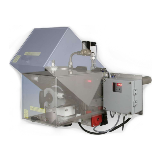
GAS 222.21 1.5 Product Description Probe Description GAS 222.21 Probe with inlet and/or outlet filter, shut-off valve and blowback connection Accessories Please refer to the data sheet at the end of this manual for accessories for this probe BE460046 ◦ 09/2021... -
Page 8: Safety Instructions
GAS 222.21 2 Safety instructions 2.1 Important advice Operation of the device is only valid if: – the product is used under the conditions described in the installation- and operation instruction, the intended application according to the type plate and the intended use. In case of unauthorized modifications done by the user Bühler Technolo- gies GmbH can not be held responsible for any damage, –... -
Page 9: General Hazard Warnings
GAS 222.21 2.2 General hazard warnings The equipment must be installed by a professional familiar with the safety requirements and risks. Be sure to observe the safety regulations and generally applicable rules of technology relevant for the installation site. Prevent malfunctions and avoid personal injuries and property damage. -
Page 10: Transport And Storage
GAS 222.21 3 Transport and storage Only transport the product inside the original packaging or a suitable alternative. The equipment must be protected from moisture and heat when not in use. They must be stored in a covered, dry and dust-free room at a temperature between -20 °C to 50 °C (-4 °F to 122 °F). -
Page 11: Installation And Connection
GAS 222.21 4 Installation and connection 4.1 Installation site requirements Sample gas probes are intended for flange mounting. – Installation site and installation position are determined based on requirements specific to the application. – If necessary, the connection piece should be slightly tilted toward the centre of the channel. -
Page 12: Connecting The Gas Line
GAS 222.21 4.6 Connecting the Gas Line The sample gas line must be carefully and properly connected using a suitable fitting. This table provides an overview of the sample gas probe connections: Probe Reservoir Ball valve Control valve GAS 222... -
Page 13: Connecting The Gas Line
GAS 222.21 4.6.2 Connecting the Gas Line Please note the following items when connecting the sample gas line (NPT 1/4") on heated probes to prevent thermal bridges: – Choose the shortest possible screw connection. – Shorten the connection pipe for the sample gas line as much as possible. To do so, remove the insulation around the sample gas line. -
Page 14: Electrical Connections
GAS 222.21 4.8 Electrical connections WARNING Hazardous electrical voltage The device must be installed by trained staff only. CAUTION Wrong mains voltage Wrong mains voltage may damage the device. Regard the correct mains voltage as given on the type plate. -
Page 15: Operation And Control
GAS 222.21 5 Operation and Control NOTICE The device must not be operated beyond its specifications. WARNING Housing or component damage Never exceed the maximum working pressure and temperature range of the drive. 5.1 Basic function of the probe controller 5.1.1 Regulator Functions... -
Page 16: Use Of Menu Functions
GAS 222.21 5.2 Use of menu functions Overview of the operational principal: Use this short description if you have experience with the device. Operation is carried out by only the keys with the following functions: Function – Switch from measurement display to main menu –... -
Page 17: Menu Navigation Overview
GAS 222.21 5.2.1 Menu Navigation Overview Temperature and status display Display ____ The probe temperature is indicated in 0.5°C increments. Press the Enter key to access the main menu. The temperature can be displayed in Celsius or Fahrenheit. During operation the conditions of the... -
Page 18: Detailed Description Of The Operational Principle
GAS 222.21 5.2.2 Detailed description of the operational principle The detailed description will guide you through the menu step by step. Connect the unit to the power supply and wait for the startup procedure to complete. At first the software version im- plemented on the unit will be displayed for a brief period. -
Page 19: Probe Controller Submenu [Display: Prob]
GAS 222.21 5.3.2 Probe Controller Submenu [Display: Prob] Regulator -> Target temperature (Temperature) This setting is for the device temperature target value. The value can be set within a range from 50 °C (122 °F) to 200 °C (392 °F). -
Page 20: Submenu Blowback Control [Display: Bbc] (Optional)
GAS 222.21 5.3.4 Submenu Blowback control [Display: bbc] (optional) Blowback control -> Control mode Under this menu item you can switch between automatic blowback and manual operation. When selecting Hand, the display will alternate between displaying the temperature and "Hand". -
Page 21: Maintenance
GAS 222.21 6 Maintenance During maintenance, remember: – The equipment must be maintained by a professional familiar with the safety requirements and risks. – Only perform maintenance work described in these operating and installation instructions. – When performing maintenance of any type, observe the respective safety and operation regulations. -
Page 22: Maintaining The Filter Element
GAS 222.21 CAUTION Do not attach levers or tools to the drive’s spindle! Levers and tools on the spindle can flap around when switching the compressed air or control voltage back on and cause serious injury or damage! NOTICE Under normal operating and ambient conditions the slew drive maintenance free. -
Page 23: Replacing The Outlet Filter With Micro-Fibreglass Filter Element
GAS 222.21 6.1.2 Replacing the Outlet Filter with Micro-Fibreglass Filter Element – Turn the handle at the rear end of the probe by 90° (handle must be horizontal), pushing in slightly, and remove. – Unscrew the dirty filter element counter-clockwise from the thread of the handle. -
Page 24: Inlet Filter Blowback (Within The Process Stream)
GAS 222.21 Condensate inside the pressure vessel Depending on the installation site and application conditions a small amount of condensate may form inside the blowback air pressure vessel. Open the drain screw at the bottom of the vessel and drain the condensate at least once a year. -
Page 25: Built-In Blowback Control (Optional)
GAS 222.21 6.2.3 Built-In Blowback Control (Optional) All required parts are already built into the probe based on your purchase order. Switching on the probe will first automatically trigger blowback. The set blowback interval will then start. The display will indicate blowback. During the process the display will alternate between displaying the temperature and "bbon"... -
Page 26: Service And Repair
GAS 222.21 7 Service and repair This chapter contains information on troubleshooting and correction should an error occur during operation. Repairs to the unit must be performed by Bühler authorised personnel. Please contact our Service Department with any questions: Tel.: +49-(0)2102-498955 or your agent If the equipment is not functioning properly after correcting any malfunctions and switching on the power, it must be inspected by the manufacturer. -
Page 27: Spare Parts And Accessories
GAS 222.21 7.2 Spare Parts and Accessories Please also specify the model and serial number when ordering parts. Upgrade and expansion parts can be found in our catalog. Available spare parts: Item no. Description 91 100 000 01 Fuse 115 V/230 V: 800 mA delayed action... -
Page 28: Disposal
GAS 222.21 8 Disposal Dispose of parts so as not to endanger the health or environment. Follow the laws in the country of use for disposing of elec- tronic components and devices during disposal. Bühler Technologies GmbH BE460046 ◦ 09/2021... -
Page 29: Appendices
GAS 222.21 9 Appendices 9.1 Technical Data Gas Probe Technical Data Probe operating temperature: max. 200 °C Ambient temperature without accessories: -20 to +80 °C Ambient temperature with accessories: Component Ambient temperature range Compressed air valve: -10 °C < T <... -
Page 30: Dimensions
GAS 222.21 9.3 Dimensions Bühler Technologies GmbH BE460046 ◦ 09/2021... -
Page 31: Connection Diagram
GAS 222.21 9.4 Connection Diagram Mains BE460046 ◦ 09/2021 Bühler Technologies GmbH... -
Page 32: Connection Diagram Heated Pressure Vessel
GAS 222.21 9.5 Connection diagram heated pressure vessel Heater Operating voltage 115-230 V AC 200 W 30 Bühler Technologies GmbH BE460046 ◦ 09/2021... -
Page 33: User Book (Please Make Copies)
GAS 222.21 9.6 User book (Please make copies) Maintained on Unit no. Operating hours Remarks Signature BE460046 ◦ 09/2021 Bühler Technologies GmbH... -
Page 34: Attached Documents
GAS 222.21 10 Attached Documents – Declaration of Conformity KX460012 – Accessories Data Sheet 461099 – RMA - Decontamination Statement Bühler Technologies GmbH BE460046 ◦ 09/2021... - Page 36 Accessories for Sample Gas Probe GAS 222 § Downstream filters § Sample tubes § Capacitive vessel § In-situ filters § Cal gas connections § Pneumatic actuators § Extensions § Adapter flanges § 3/2-way-solenoid valves § Blowback controllers Page 2 - 4 Page 8 Page 5 - 7 For general information, see data sheet “Sample gas probes GAS 222”...
- Page 37 Sample tubes, in-situ filters and extensions § Various materials § Various dimensions § Heated or nonheated extensions Sample tube T max. Material Length Part No.: 1.4571 462220010300 600°C 300 mm X X X X X X X X X X X X X X 1.4571 500 mm...
- Page 38 Sample tubes, in-situ filters and extensions § Various materials § Various dimensions § Heated or nonheated extensions In-situ filter Material T max. Length Pore size Part No.: stainless steel 600°C 237 mm 5 µm 46222303 stainless steel 237 mm 0.5 µm 46222303F* 600°C Hastelloy...
- Page 39 Sample tubes, in-situ filters and extensions § Various materials § Various dimensions § Heated or nonheated extensions Protection shield Part No.: for in-situ filter 03 462223034 for in-situ filter 04 462223044 Extensions Material Mains voltage Length G3/4 nonheated 1.4571 4622230320200 X X X X X X X X X X X X...
- Page 40 Entnahmerohre / tubes Verlängerungen / extensions ø Unbeheizt / unheated var. G3/4 Тyp var. G3/4 G3/4 0,2-2 m G3/4 var. 21,3 G3/4 G1/2 0,25-1,5m G1/2 var. G3/4 var. G3/4 var. G3/4 ø 02-0,5 24 G3/4 36 Beheizt / heated 02-1,0 1000 24 G3/4 36 Тyp ø...
- Page 41 Blowback § With ball valve or solenoid valve § Heated or nonheated § Manuell or automatic contro Ambient Capacitive vessel Part No.: temperature PAV 01 46222PAV Accessories for capacitive vessel ball valve 46222PAVKH 2/2-way-MV 24VDC* -10 ... +55°C 46222PAVMV1 2/2-way-MV 110V 50Hz -10 ...
- Page 42 Details: A) Blowback Ordering note for capacitive vessel: For attachment to GAS 222.11 / 30 / 35-U, a support is required. Ordering note for pneumatic actuator: If a blowback controller is required, only actuator P/N 46222030 is possible. We advise the installation of a position indicator switch to control the pneumatic actuator. Integrated blowback controller in the probe controller In addition to the stand-alone blowback controller (RRS), an integrated blowback controller is optionally available...
- Page 44 Downstream filter elements and further options Downstream filter Part no.: Material O-Rings Pore size 46222026 Ceramics Viton 3 µm X X X X X X X X X X X X X X Ceramics 3 µm 46222026P X X X X X X X X X X X X X X...
- Page 45 RMA-Formular und Erklärung über Dekontaminierung RMA-Form and explanation for decontamination RMA-Nr./ RMA-No. Die RMA-Nummer bekommen Sie von Ihrem Ansprechpartner im Vertrieb oder Service./ You may obtain the RMA number from your sales or service representative. Zu diesem Rücksendeschein gehört eine Dekontaminierungserklärung. Die gesetzlichen Vorschriften schreiben vor, dass Sie uns diese Dekontaminierungserklärung ausgefüllt und unterschrieben zurücksenden müssen.
- Page 46 Dekontaminierungserklärung DE000011 Bühler Technologies GmbH, Harkortstr. 29, D-40880 Ratingen 01/2019 Tel. +49 (0) 21 02 / 49 89-0, Fax: +49 (0) 21 02 / 49 89-20 E-Mail: service@buehler-technologies.com Internet: www.buehler-technologies.com...
Need help?
Do you have a question about the GAS 222.21 and is the answer not in the manual?
Questions and answers