Table of Contents
Advertisement
Quick Links
Gas Analysis
Gas Analyser for maritime emission monitoring
BA 3 MA
Installation and Operation Instructions
Original instructions
BE550027
Bühler Technologies GmbH, Harkortstr. 29, D-40880 Ratingen
11/2021
Tel. +49 (0) 21 02 / 49 89-0, Fax: +49 (0) 21 02 / 49 89-20
E-Mail: analyse@buehler-technologies.com
Internet: www.buehler-technologies.com
Advertisement
Table of Contents

Related Manuals for Bühler technologies BA 3 MA


Summary of Contents for Bühler technologies BA 3 MA
- Page 1 Gas Analysis Gas Analyser for maritime emission monitoring BA 3 MA Installation and Operation Instructions Original instructions BE550027 Bühler Technologies GmbH, Harkortstr. 29, D-40880 Ratingen 11/2021 Tel. +49 (0) 21 02 / 49 89-0, Fax: +49 (0) 21 02 / 49 89-20 E-Mail: analyse@buehler-technologies.com...
- Page 2 Bühler Technologies GmbH, Harkortstr. 29, D-40880 Ratingen Tel. +49 (0) 21 02 / 49 89-0, Fax: +49 (0) 21 02 / 49 89-20 Internet: www.buehler-technologies.com E-Mail: analyse@buehler-technologies.com Read this instruction carefully prior to installation and/or use. Pay at- tention particularly to all advises and safety instructions to prevent in- juries.
-
Page 3: Table Of Contents
BA 3 MA Contents Introduction ............................................. 3 Intended Use......................................... 3 Equipment configuration .................................... 3 Scope of delivery ........................................ 3 Safety instructions ......................................... 4 Important notices........................................ 4 General hazard warnings .................................... 5 Technical description ........................................ 7 Configuration ........................................ 7 Equipment overview ...................................... 9 Gas flow diagrams ...................................... 10 Principles of measurement ..................................... - Page 4 BA 3 MA Cleaning .......................................... 43 Replacing fuses ........................................ 43 Service list ........................................... 44 9 Service and repair......................................... 45 Status messages and troubleshooting ............................... 45 9.1.1 Service Log messages .................................. 45 9.1.2 Failure Log messages .................................. 46 9.1.3 Calibration Log messages ................................ 47 Spare parts .......................................... 47 10 Disposal ............................................
-
Page 5: Introduction
BA 3 MA 1 Introduction 1.1 Intended Use The BA 3 MA gas analyser serves the continuous measurement of SO and CO flue gas emissions in maritime applications (mar- ine engines). It can particularly be used to monitor compliance with exhaust emission standards (quotient of SO [ppm/ Vol.-%] associated with SO... -
Page 6: Safety Instructions
BA 3 MA 2 Safety instructions 2.1 Important notices This unit may only be used if: – The product is being used under the conditions described in the operating- and system instructions, used according to the nameplate and for applications for which it is intended. Any unauthorized modifications of the device will void the warranty provided by Bühler Technologies GmbH,... -
Page 7: General Hazard Warnings
BA 3 MA 2.2 General hazard warnings The equipment must be installed by a professional familiar with the safety requirements and risks. Be sure to observe the safety regulations and generally applicable rules of technology relevant for the installation site. Prevent malfunctions and avoid personal injuries and property damage. - Page 8 BA 3 MA DANGER Potentially explosive atmosphere Explosion hazard if used in hazardous areas. The device is not suitable for operation in hazardous areas with potentially explosive at- mospheres. Do not expose the device to combustible or explosive gas mixtures.
-
Page 9: Technical Description
BA 3 MA 3 Technical description 3.1 Configuration The BA 3 MA is a 19 inch rack device for stationary mounting (IP20 protection class for indoor installation). The core component of the device is a combination of two gas sensors. On one hand it uses an optical NDUV SO sensor (non-dispersive UV spectro- scopy). - Page 10 BA 3 MA Channel markings The channels on the unit are marked as follows: Symbol Explanation vpm trace measurement (smallest measuring range 0-100 ppm) via NDUV sensor Vol.% measurement (smallest measuring range 0-10 Vol.%) via NDIR sensor Operand (quotient) from SO and CO measurements [ppm/Vol.%]...
-
Page 11: Equipment Overview
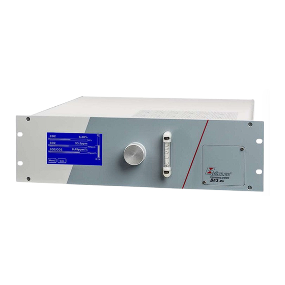
BA 3 MA 3.2 Equipment overview The following views explain the elements of the analyser. 19" / 482,6 mm Fig. 1: BA 3 MA, front view Touchscreen and measurement display Sample gas filter (optional) Flow meter, varies by number of channels Maintenance door Fig. 2: BA 3 MA, rear view... -
Page 12: Gas Flow Diagrams
BA 3 MA 3.3 Gas flow diagrams The analyser is equipped with an optical NDUV SO sensor and an optical NDIR-CO sensor. The sensors are connected to hoses in series in a common gas path. Therefore the same sample gas flows through them < 0.5 sec. apart. -
Page 13: Principles Of Measurement
BA 3 MA 3.4 Principles of measurement The gas concentration is measured using non-dispersive (ND) absorption spectroscopy. Here the degree of radiation absorption (in the gas to be measured) is a dimension for the gas concentration. The radiation enters the measuring chamber the sample gas flows through at an intensity of Io. - Page 14 BA 3 MA Parts in contact with sample gas Component Materials in contact with media Pump: PET, PPS Flow regulator: PTFE, stainless steel (1.4571) Gas lines: FPM (Viton), stainless steel (1.4571) Solenoid valves: PVDF or stainless steel (1.4571) Gas ducts: PVDF or stainless steel (1.4571)
-
Page 15: Transport And Storage
BA 3 MA 4 Transport and storage Transport The unit is sensitive to shock and vibration. Therefore, where possible, transport in the original packaging or large, sturdy pack- aging at a minimum consisting of 3 layer carton, plastic or aluminium sheet. Line the inside of the packaging with padding at least 10 cm thick on all sides. -
Page 16: Installation And Connection
BA 3 MA 5 Installation and connection NOTICE Unit with specially cleaned gas paths Protect parts in contact with media, e.g. bulkhead couplings, from recontamination. Use clean work cloves, clothing and clean tools when connecting, particularly when connect- ing the gas paths. Only charge specially cleaned gas paths with oil-free inert gases or oil- free compressed air apart from the gas for the actual measuring task. -
Page 17: Sample Gas Conditioning
BA 3 MA 5.2.1 Sample gas conditioning To ensure the least possible interference and low analyser maintenance the gas inlet requirements (Technical Data) must be ob- served as consistently as possible. Further avoid dirt on any parts the sample gas flows through. - Page 18 The back of the unit will have the respective number of gas connections and terminal strips for signal outputs based on the number of measuring channels. Fig. 3: BA 3 MA, rear view gas in Sample gas input...
-
Page 19: Electrical Connections
BA 3 MA 5.2.3 Electrical connections 5.2.3.1 Signal outputs Two or three 16-pin PHÖNIX plugs (ST0 to ST3) are located at the back of the analyser for the input and output signals. Plug ST4 is configured to signal the measuring ranges or the measuring range switchover. To prevent interference, the signal lines should be routed isolated from the power lines. - Page 20 BA 3 MA Plug 4 Pin Function Description / Status Connection data NC contact Ch. 1 measuring range 1 Relay, max. switching power 125 V AC/1 A or 60 V DC/1 A 2 Common 3 NO contact Ch. 1 measuring range 2 4 NC contact Ch. 2 measuring range 1 Relay, max.
- Page 21 BA 3 MA 5.2.3.4 Modbus Communication Communication via Modbus is always initiated by the client (request). The server (typically) responds to the request with a re- sponse. A Modbus frame for a request/response always has the following structure: Address field (A)
-
Page 22: Initial Operation
BA 3 MA 6 Initial operation CAUTION Heating due to turbulences To avoid turbulences, only charge the analyser by slowly opening the fittings. Adiabatic compression To avoid potential adiabatic compression, operation with closed gas outputs prohibited. 6.1 Process Preparation Please ensure –... -
Page 23: Overview Of Key Factory Settings
BA 3 MA 6.2 Overview of key factory settings Check if the factory settings are suitable for your measurement task. If necessary, change them as described in chapter "Opera- tion and Control". The following table lists the key parameters: Check if the factory settings are suitable for your measurement task. If necessary, change these as described in chapter "Menu >... -
Page 24: Operation And Control
BA 3 MA 7 Operation and Control NOTICE The device must not be operated beyond its specifications. 7.1 Menu overview and operating principle The analyser is controlled via the touch display. NOTICE Delicate display The touch display is delicate. Do not use sharp or pointy objects such as pens, screw- drivers, etc. - Page 25 Sets the permitted deviation from the measuring range (MR) Period PWD 2 Enter Set sample gas cal. period and purging time Logbook PWD 1 Enter Calibration history (with date/time) Fig. 4: BA 3 MA Menu overview BE550027 ◦ 11/2021 Bühler Technologies GmbH...
-
Page 26: General Information For Navigating The Menu
BA 3 MA 7.1.1 General information for navigating the menu Measurement The normal mode the analyser will show the measurement screen. 6,30% screen It will show: 53,5ppm – the current measurement value of each cell as a bar graph and... - Page 27 BA 3 MA Extra buttons In addition to the buttons, the menus may also have extra buttons: Auto Calibration: The buttons have different functions depending Zero Gas 0,0 % on the context: 15,0 % Span Gas – Select measuring cell or All channels...
-
Page 28: Menu > Diagnostics
BA 3 MA 7.2 Menu > Diagnostics The Diagnostics menu contains the following menu items: This logbook lists all failures which have occurred including Diagnostics Failure/ channel number, date, time and error message in plain text. Failure Log Status logbook Outstanding service is recorded in the service log. -
Page 29: Menu > Diagnostics > Service Log
BA 3 MA 7.2.2 Menu > Diagnostics > Service Log This logbook lists the required service. If an entry exists, the measurement channel will flash at the respective channel. W Service Diagnostics Menu > Diagnostics > Service Log to open the log- book and enter the password. -
Page 30: Menu > Base Settings
BA 3 MA 7.3 Menu > Base Settings Use the base settings menu to configure the device settings. Menu Description Language Choose from German and English as the menu language. Passwords Add passwords 1 and 2 or enable / disable password protect Pressure sensor Here enter the current air pressure. -
Page 31: Menu > Base Settings > Language
BA 3 MA 7.3.2 Menu > Base Settings > Language Changing the Base Settings Menu > Base Settings > Language to open the drop- menu language down menu. Language Passwords Date/Time Pressure sensor Pumps Meas Esc. Select the language and press to confirm your input. -
Page 32: Menu > Base Settings > Date/Time
BA 3 MA 7.3.4 Menu > Base Settings > Date/Time To set the current date and (local) time: Setting the date / Press Menu > Base settings > Date/Time: time Date/Time Date 16.07.21 Now select Date or Time . Time 11:14:50 AM Esc. -
Page 33: Menu > Channel Settings > Meas. Range
BA 3 MA 7.4.1 Menu > Channel Settings > Meas. Range You can define measuring range MR1 and MR2 for each channel. The settings will affect the output via the analogue output. The measuring range the unit is in can optionally be indicated via relay outputs. -
Page 34: Menu > Channel Settings > Limits
BA 3 MA 7.4.2 Menu > Channel Settings > Limits You may define two limits per channel and choose whether to signal if the respective limit is overrun or underrun. The signal will be output via the RS232 port, the relay outputs at the back of the unit and with notifications in the unit's display. - Page 35 BA 3 MA spective active measuring range. Please note, in automatic switchover the measuring ranges of the end value will automatic- ally be adjusted. This must be considered when analysing the ana- logue signal. Cal./Error You can further define the behaviour of the analog output on cal- Analog Output: ibration and failures.
-
Page 36: Menu > Channel Settings > Units
BA 3 MA 7.4.4 Menu > Channel Settings > Units Units Open Menu > Channel Settings > Units: Units . Select the channel using Display Now select Display . Esc. Meas Now select the unit with . Depending on the cell Units: type you will be able to choose from various units. -
Page 37: General Information
BA 3 MA 7.5.1 General information The properties of measuring instruments change over time due to components ageing or due to changes in ambient or process conditions. The resulting change in the measurement values is referred to as drift. To be able to measure with adequate accurate the unit regularly needs to be calibrated. This particularly applies when measur- ing very low gas concentrations. - Page 38 BA 3 MA 7.5.1.1 Calibrating gases In calibration we generally distinguish between zero gas calibration (1st Reference point; zero point of the unit) and range calib- ration (calibrating a second reference point for greater accuracy. This requires two different gases:...
-
Page 39: Menu > Calibration > Period
BA 3 MA 7.5.2 Menu > Calibration > Period Period Calibration Select Menu > Calibration > Duration . Auto Manual Enter password 2 and press to confirm. Duration Logbook Meas Esc. You can now set the calibration period and purging time. -
Page 40: Menu > Calibration > Auto
BA 3 MA 7.5.4 Menu > Calibration > Auto Auto-calibration Calibration Select Menu > Calibration > Auto . Auto Manual Enter password 2 and press to confirm. Duration Logbook Meas Esc. The correct CO concentration for your application must be set. -
Page 41: Menu > Calibration > Manual
BA 3 MA 7.5.5 Menu > Calibration > Manual A manual calibration may be performed at any time. Manual Calibration Select Calibration Menu > Channel settings > Manual . Auto Manual Enter password 2. Duration Now select All channels or use the arrow keys to navigate to the channel to be calibrated. - Page 42 BA 3 MA If an error message is triggered, proceed as follows: Verify – the unit had adequate time to warm up (at least 30 min) and stable operating conditions were reached. – Calibrating gases are loaded in the desired concentration, –...
-
Page 43: Maintenance
BA 3 MA 8 Maintenance During maintenance, remember: – The equipment must be maintained by a professional familiar with the safety requirements and risks. – Only perform maintenance work described in these operating and installation instructions. – When performing maintenance of any type, observe the respective safety and operation regulations. -
Page 44: Leak Test
BA 3 MA 8.3 Leak test Interval approx. 6 months (recommended) Leak test procedure Sample gas conditioning Fig. 5: Leak test set-up Close the sample gas outlet on the analyser (2) and the sample gas inlet of your gas conditioning system gas tight (e.g. using a shut-off cock (1) + (3)). -
Page 45: Replace Filter Element
The BA 3 MA has two fuses at the back of the unit, F1 and F2. Fig. 6: BA 3 MA, rear view, fuses F1 is the fuse for the internal 24 V DC supply. F2 is built into the power socket and fuses the mains supply. -
Page 46: Service List
BA 3 MA 8.7 Service list Service list BA 3 MA Serial number Location Date Service performed Name Signature 44 Bühler Technologies GmbH BE550027 ◦ 11/2021... -
Page 47: Service And Repair
BA 3 MA 9 Service and repair This chapter contains information on troubleshooting and correction should an error occur during operation. Repairs to the unit must be performed by Bühler authorised personnel. Please contact our Service Department with any questions: Tel.: +49-(0)2102-498955 or your agent... -
Page 48: Failure Log Messages
BA 3 MA 9.1.2 Failure Log messages Errors which occur during operation are saved to the failure logbook Open: > > Menu Diagnostics Failure Logbook Logbook message Symbol Possible cause Action <Cell Type> low temp The cell temperature was temporarily be- –... -
Page 49: Calibration Log Messages
BA 3 MA 9.1.3 Calibration Log messages Errors which occur during calibration are saved to the calibration logbook. Open: > > Menu Calibration Logbook Logbook message Symbol Possible cause Action Cal. variation failure Excessive variation during calibration. Maintain a stable calibrating gas concen- A... -
Page 50: Disposal
BA 3 MA 10 Disposal The applicable national laws must be observed when disposing of the products. Disposal must not result in a danger to health and environment. The crossed out wheelie bin symbol on Bühler Technologies GmbH electrical and electronic products indicates special disposal notices within the European Union (EU). -
Page 51: Attached Documents
BA 3 MA 11 Attached documents – Declaration of Conformity KX550012 – Modbus manual BA 3 MA – RMA - Decontamination Statement BE550027 ◦ 11/2021 Bühler Technologies GmbH... - Page 54 Gas Analysis Modbus TCP manual BA 3 MA BE550028 Bühler Technologies GmbH, Harkortstr. 29, D-40880 Ratingen Tel. +49 (0) 21 02 / 49 89-0, Fax: +49 (0) 21 02 / 49 89-20 03/2022 E-Mail: analyse@buehler-technologies.com page 1 / 18 Internet: www.buehler-technologies.com...
- Page 55 Modbus TCP manual BA 3 MA Modbus TCP interface The Modbus interface allows direct access to process and diagnostic data and parameters during operation based on VDI4201. The analyser takes on the role of the server in communication. Modbus TCP: Connects at the back of the device via RJ45 port.
- Page 56 Modbus TCP manual BA 3 MA By default, the new value will be applied to the write registers during writing without any other interaction. For some registers, simply writing them will not suffice. Once written, the change must be confirmed with another entry in a different register.
- Page 57 Modbus Register Description Address Number of Access Data type Default Selection Resol- Unit Pass- Comment registers ution word Measurement value 2000 Float None channel 1 Measurement value 2002 Int32 None channel 1 - status Measurement value 2004 Float None channel 2 Measurement value 2006 Int32...
- Page 58 Description Address Number of Access Data type Default Selection Resol- Unit Pass- Comment registers ution word Max. Measuring range 2 3, 16 6018 Float Ch. 1 Min. Measuring range 2 3, 16 6020 Float Ch. 2 Max. Measuring range 2 3, 16 6022 Float...
- Page 59 Description Address Number of Access Data type Default Selection Resol- Unit Pass- Comment registers ution word Auto switchover EA Ch. 2 3, 16 6049 Int16 Auto switchover EA Ch. 3 3, 16 6050 Int16 Auto switchover EA Ch. 4 3, 16 6051 Int16 Limit value 1 Ch.
- Page 60 Description Address Number of Access Data type Default Selection Resol- Unit Pass- Comment registers ution word Damping Ch. 2 3, 16 6101 Int16 Damping Ch. 3 3, 16 6102 Int16 Damping Ch. 4 3, 16 6103 Int16 Config. analog 3, 16 6130 Int16 Bit15-Bit12: Value at...
- Page 61 Description Address Number of Access Data type Default Selection Resol- Unit Pass- Comment registers ution word Zero gas manual 3, 16 6156 Float calibration Ch. 4 Zero gas manual 3, 16 6158 Float calibration all cells Span gas manual 3, 16 6160 Float calibration Ch.
- Page 62 Description Address Number of Access Data type Default Selection Resol- Unit Pass- Comment registers ution word Cal. period all cells 3, 16 6244 Uint16 Purging time Ch. 1 3, 16 6245 Uint16 Purging time Ch. 2 3, 16 6246 Uint16 Purging time Ch.
- Page 63 Description Address Number of Access Data type Default Selection Resol- Unit Pass- Comment registers ution word Pressure Ch. 2 6518 Float None Pressure Ch. 3 6520 Float None Pressure Ch. 4 6522 Float None Alarm logbook entry 6550 Struct number Alarm logbook entry 1 6551 Struct...
- Page 64 Description Address Number of Access Data type Default Selection Resol- Unit Pass- Comment registers ution word Alarm logbook entry 24 6620 Struct Alarm logbook entry 25 6623 Struct Alarm logbook entry 26 6626 Struct Alarm logbook entry 27 6629 Struct Alarm logbook entry 28 6632 Struct...
- Page 65 Description Address Number of Access Data type Default Selection Resol- Unit Pass- Comment registers ution word Service logbook entry 10 3 6708 Struct Service logbook entry 11 6711 Struct Service logbook entry 12 3 6714 Struct Service logbook entry 13 3 6717 Struct Service logbook entry 14 3...
- Page 66 Description Address Number of Access Data type Default Selection Resol- Unit Pass- Comment registers ution word Calibration logbook 1 6811 Struct Register 1 = Channel and error code Bit15-Bit8: Channel number 0 to 3 same as 1 to 4 Bit7-Bit0: Error code registers 2 + 3 = time (unix timestamp) Calibration logbook 2...
- Page 67 Description Address Number of Access Data type Default Selection Resol- Unit Pass- Comment registers ution word Enable limit value 2 Ch. 2 1, 5, 15 45013 1 = Enable 0 = Disable Enable limit value 1 Ch. 3 1, 5, 15 45014 1 = Enable 0 = Disable Enable limit value 2 Ch.
- Page 68 Description Address Number of Access Data type Default Selection Resol- Unit Pass- Comment registers ution word Calibrate zero gas Ch. 4 5, 15* 45508 1 = Start calibration Write with function 0 = Cancel calibra- code 15 only with tion quantity = 1 Calibrate span gas Ch.
- Page 69 Description Address Number of Access Data type Default Selection Resol- Unit Pass- Comment registers ution word UV_error_cell 47025 None UV_heater_defective 47026 None UV_T-sensor_defective 47027 None reserved 47028 None reserved 47029 None reserved 47030 None reserved 47031 None CO2_limit_1_exceeded 47056 None CO2_limit_1_underrun 47057 None...
- Page 70 Description Address Number of Access Data type Default Selection Resol- Unit Pass- Comment registers ution word reserved 47111 None Cal_variation_high 47112 None Cal_devi- 47113 None ation_span_gas_high Cal_devi- 47114 None ation_zero_gas_high Cal_successful 47115 None Cal_invalid_error 47116 None reserved 47117 None reserved 47118 None reserved...
- Page 71 Description Address Number of Access Data type Default Selection Resol- Unit Pass- Comment registers ution word Measuring range status 47138 None Ch. 3 Measuring range status 47139 None Ch. 0 reserved 47140 None reserved 47141 None reserved 47142 None reserved 47143 None...
- Page 72 RMA-Formular und Erklärung über Dekontaminierung RMA-Form and explanation for decontamination RMA-Nr./ RMA-No. Die RMA-Nr. bekommen Sie von Ihrem Ansprechpartner im Vertrieb oder Service. Bei Rücksendung eines Altgeräts zur Entsorgung tragen Sie bitte in das Feld der RMA-Nr. "WEEE" ein./ You may obtain the RMA number from your sales or ser- vice representative.
- Page 73 Dekontaminierungserklärung DE000011 Bühler Technologies GmbH, Harkortstr. 29, D-40880 Ratingen 12/2022 Tel. +49 (0) 21 02 / 49 89-0, Fax: +49 (0) 21 02 / 49 89-20 E-Mail: service@buehler-technologies.com Internet: www.buehler-technologies.com...
Need help?
Do you have a question about the BA 3 MA and is the answer not in the manual?
Questions and answers