Table of Contents
Troubleshooting

Related Manuals for Fronius CU 800i


Summary of Contents for Fronius CU 800i
- Page 1 / Perfect Charging / Perfect Welding / Solar Energy Operating instructions CU 800i CU 1100i CU 1200i CU 1400i 42,0426,0115,EN 001-13012022 Fronius prints on elemental chlorine free paper (ECF) sourced from certified sustainable forests (FSC).
-
Page 3: Table Of Contents
Coolant pump service life in cooling units for multi-shift operation Warning notices on the device Overview Connections and mechanical components Connections and mechanical components Connections and mechanical components: CU 1100i, CU 1200i, CU 1400i Connections and mechanical components: CU 800i Installation and commissioning Before installation and commissioning Safety... - Page 4 Disconnecting the cooling unit from the power source Troubleshooting Troubleshooting Safety Troubleshooting Turning the coolant pump shaft on the CU 800i, CU 1100i, CU 1100i /MV Safety Turning the coolant pump shaft Care, maintenance and disposal Care, maintenance and disposal...
-
Page 5: Safety Rules
Safety rules Explanation of DANGER! safety notices Indicates immediate danger. ▶ If not avoided, death or serious injury will result. WARNING! Indicates a potentially hazardous situation. ▶ If not avoided, death or serious injury may result. CAUTION! Indicates a situation where damage or injury could occur. ▶... -
Page 6: Environmental Conditions
The device is intended solely for the welding processes specified on the rating plate. Any use above and beyond this purpose is deemed improper. The manufacturer shall not be held liable for any damage arising from such usage. Proper use includes: carefully reading and following all the instructions given in the operating instructions studying and obeying all safety and danger notices carefully performing all stipulated inspection and maintenance work. -
Page 7: Protecting Yourself And Others
This may affect a number device types in terms of: Connection restrictions Criteria with regard to the maximum permissible mains impedance Criteria with regard to the minimum short-circuit power requirement at the interface with the public grid see "Technical data" In this case, the plant operator or the person using the device should check whether the device may be connected, where appropriate by discussing the matter with the power supply company. -
Page 8: Danger From Toxic Gases And Vapours
Danger from tox- The fumes produced during welding contain harmful gases and vapours. ic gases and va- Welding fumes contain substances that cause cancer, as stated in Monograph 118 of the pours International Agency for Research on Cancer. Use at-source extraction and a room extraction system. If necessary, use a welding torch with an integrated extraction device. -
Page 9: Risks From Mains Current And Welding Current
Risks from mains An electric shock is potentially life threatening and can be fatal. current and weld- Do not touch live parts either inside or outside the device. ing current During MIG/MAG welding and TIG welding, the welding wire, the wirespool, the feed rollers and all pieces of metal that are in contact with the welding wire are live. -
Page 10: Meandering Welding Currents
Meandering weld- If the following instructions are ignored, meandering welding currents can develop with ing currents the following consequences: Fire hazard Overheating of parts connected to the workpiece Damage to ground conductors Damage to device and other electrical equipment Ensure that the workpiece is held securely by the workpiece clamp. Attach the workpiece clamp as close as possible to the area that is to be welded. -
Page 11: Emf Measures
Earthing of the workpiece If necessary, establish an earth connection using suitable capacitors. Shield, if necessary Shield other devices nearby Shield the entire welding installation EMF measures Electromagnetic fields may pose as yet unknown risks to health: Effects on the health of persons in the vicinity, e.g. those with pacemakers and hear- ing aids Individuals with pacemakers must seek advice from their doctor before approaching the device or any welding that is in progress... -
Page 12: Requirement For The Shielding Gas
Use only suitable load-carrying equipment supplied by the manufacturer when transport- ing devices by crane. Hook chains or ropes onto all suspension points provided on the load-carrying equipment. Chains and ropes must be at the smallest angle possible to the vertical. Remove gas cylinder and wirefeeder (MIG/MAG and TIG devices). -
Page 13: Danger From Escaping Shielding Gas
If the shielding gas cylinder is not connected, leave the valve cap in place on the cylin- der. The manufacturer's instructions must be observed as well as applicable national and in- ternational regulations for shielding gas cylinders and accessories. Danger from es- Risk of suffocation from the uncontrolled escape of shielding gas caping shielding Shielding gas is colourless and odourless and, in the event of a leak, can displace the... -
Page 14: Commissioning, Maintenance And Repair
Never bypass or disable safety devices. Before switching on the device, ensure that no one is likely to be endangered. Check the device at least once a week for obvious damage and proper functioning of safety devices. Always fasten the shielding gas cylinder securely and remove it beforehand if the device is to be transported by crane. -
Page 15: Disposal
(e.g. relevant product standards of the EN 60 974 series). Fronius International GmbH hereby declares that the device is compliant with Directive 2014/53/EU. The full text on the EU Declaration of Conformity can be found at the follow- ing address: http://www.fronius.com... -
Page 17: General Information
General information... -
Page 19: General
The op- erating status of the cooling unit can be manually changed by selecting different op- erating modes CU 800i /460 V (standard version for 460 V TPS 270i C power sources operation) For single-shift operation The coolant pump and fan are switched on and off automatically as standard. -
Page 20: Scope Of Supply
Cooling unit description Cooling unit compatible with CU 1100i /460 V (standard version for 460 V TPS 320i - 600i power sources operation) For single-shift operation The coolant pump and fan are switched on and off automatically as standard. The op- erating status of the cooling unit can be manually changed by selecting different op- erating modes... -
Page 21: Validity Of 'General Delivery And Payment Conditions
Payment Condi- tions' CU 800i, CU 800i /460 V, CU 1100i, CU 1100i /460 V, CU 1100i /MV, CU 1100i /MV RVP: max. 8 hrs operation per day (single-shift operation) only original Fronius coolant is used... -
Page 22: Options
This option is available for the following devices: temperature CU 800i sensor CU 800i /460 V CU 800i Pro The OPT/i CU flow temperature sensor option offers monitoring of the coolant temperat- ure and flow rate. Coolant temperature monitoring and flow monitoring are parts of an installation set and cannot be ordered separately. -
Page 23: Opt/I Cu Level Sensor
OPT/i CU level This option is available for the following devices: sensor CU 1100i CU 1100i /460 V CU 1100i /MV CU 1100i /MV RVP CU 1200i Pro /MC The option is installed as standard on the CU 1400i Pro/MC cooling unit. The level sensor monitors the level of coolant in the cooling unit. -
Page 24: Service Life Of The Coolant Pumps
CU 800i, 1100i If used properly, the coolant pump will have a service cooling units for CU 800i /460 V, life of approx. 10,000 operating hours. After the end of single-shift oper- 1100i /460 V its nominal service life, the coolant pump could devel-... -
Page 25: Warning Notices On The Device
The cooling unit displays safety symbols and has a rating plate. The rating plate and safety symbols must not be removed or painted over. The symbols warn against operat- ing the equipment incorrectly, as this could result in serious injury or damage to property. Part No.: www.fronius.com Ser.No.: IEC 60 974-2/-10 Cl.A IP 23 460 V 0.35 A... -
Page 27: Connections And Mechanical Components
Connections and mechanical com- ponents... -
Page 29: Connections And Mechanical Components
Connections and mechanical components Connections and (1) (2) (10) mechanical com- ponents: CU 1100i, CU 1200i, CU 1400i Front of cooling unit Rear of cooling unit Coolant flow connection blanking cover (blue) Coolant return connection blanking cover (red) Screw cap for coolant tank Important notes on maintenance and operation Coolant viewing window Coolant return connection (red) -
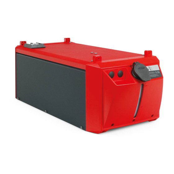
Page 30: Connections And Mechanical Components: Cu 800I
Connections and mechanical com- (1) (2) ponents: CU 800i Front of cooling unit Rear of cooling unit Coolant flow connection (blue) Coolant return connection (red) Screw cap for coolant tank Important notes on maintenance and operation Coolant viewing window Blanking cover... -
Page 31: Installation And Commissioning
Installation and commissioning... -
Page 33: Before Installation And Commissioning
Before installation and commissioning Safety WARNING! Danger from incorrect operation and work that is not carried out properly. This can result in serious personal injury and damage to property. ▶ All the work and functions described in this document must only be carried out by technically trained and qualified personnel. -
Page 34: Guarantee Provisions Regarding The Coolant Pump
Intended use The device is intended solely for use in conjunction with Fronius system components. The device is to be used exclusively for its intended purpose. Any use above and beyond this purpose is deemed improper. The manufacturer is not liable for any damage, or unexpected or incorrect results arising out of such misuse. -
Page 35: Fitting The Cooling Unit To The Trolley
Fitting the cooling unit to the trolley General The welding system can be fitted to a trolley to make the system (incl. cooling unit) more mobile. Screwing the WARNING! cooling unit to the trolley Danger due to devices toppling over. This can result in serious personal injury and damage to property. -
Page 36: Connecting The Cooling Unit To The Power Source
Connecting the cooling unit to the power source Safety WARNING! Danger from electrical current. This can result in serious personal injury and damage to property. ▶ Before starting work, switch off all devices and components involved and disconnect them from the grid. ▶... - Page 37 Use the screws supplied with the cooling unit to secure the power source to the cooling unit. Only if the cooling unit has the OPT/i CU Torch deflate option: max. 20 l/min (5.28 gal./min [US]) max. 4 bar (58.02 psi) Gas hose from the scope of delivery of the cooling unit (gas hose is only supplied if the OPT/i CU Torch deflate option is installed in the cooling unit) For gas supply...
-
Page 38: Connecting The Coolant Return Filter And Coolant Hoses
Connecting the coolant return filter and coolant hoses Safety WARNING! Danger from electrical current. This can result in serious personal injury and damage to property. ▶ Before starting work, switch off all devices and components involved and disconnect them from the grid. ▶... -
Page 39: Filling And Starting Up The Cooling Unit
Filling and starting up the cooling unit Filling the cool- WARNING! ing unit Danger from electrical current. This can result in serious personal injury and damage to property. ▶ Before starting work, switch off all devices and components involved and disconnect them from the grid. -
Page 40: Starting Up The Cooling Unit
Push the locking ring backwards until the sealing cone returns to its original position and release the locking ring again Starting up the CAUTION! cooling unit Danger from insufficient coolant in the cooling unit. This can result in severe damage to property. ▶... -
Page 41: Opt/I Cu Torch Deflate: Emptying/Filling The Torch Hosepack
CAUTION! Danger from insufficient coolant when starting the cooling unit for the first time. This can result in severe damage to property. ▶ If the cooling unit is fitted with an OPT/i CU level sensor, the OPT/i CU level sensor may cause an error message to be output if long hosepacks are being used when starting for the first time. -
Page 42: Operating Modes
Available on: All cooling units Operating status on CU 800i, CU 800i /460 V, CU 800i Pro, CU 1100i, CU 1100i /460 V, CU 1100i /MV, CU 1100i /MV RVP: Continuous. As soon as the power source is switched on, the cool- ing unit starts to work. -
Page 43: Recommended Application Of The Operating Modes
Operating Description mode Available on: CU 1200i Pro /MC, CU 1400i Pro /MC Operating status on CU 1200i Pro /MC: When welding starts, the cooling unit begins to operate, fan and coolant pump run. The coolant pump regulates to a minimum coolant flow of 1.0 l/min (0.26 gal./min [US]). -
Page 44: Disconnect The Cooling Unit From The Power Source
Disconnect the cooling unit from the power source Safety WARNING! Danger from electrical current. This can result in serious personal injury and damage to property. ▶ Before starting work, switch off all devices and components involved and disconnect them from the grid. ▶... - Page 45 Close the cover on the cooling unit connection...
-
Page 47: Troubleshooting
Troubleshooting... -
Page 49: Troubleshooting
Troubleshooting Safety WARNING! Danger from incorrect operation and work that is not carried out properly. This can result in serious personal injury and damage to property. ▶ All the work and functions described in this document must only be carried out by technically trained and qualified personnel. - Page 50 Remedy: Wait until the end of the coolant pump's cooling phase (2 - 3 minutes) Insufficient or no coolant flow (with CU 800i Pro, CU 1100i /460 V, CU 1100i /MV RVP, CU 1200i Pro /MC, CU 1400i Pro /MC):...
- Page 51 52). Contact After-Sales Service if the coolant pump shaft proves impossible to turn Welding torch becomes very hot (with CU 800i /460 V, CU 800i Pro, CU 1100i /460 V, CU 1100i /MV RVP, CU 1200i Pro /MC, CU 1400i Pro /MC):...
-
Page 52: Turning The Coolant Pump Shaft On The Cu 800I, Cu 1100I, Cu 1100I /Mv
Turning the coolant pump shaft on the CU 800i, CU 1100i, CU 1100i /MV Safety WARNING! Danger from electrical current. This can result in serious personal injury and damage to property. ▶ Before starting work, switch off all devices and components involved and disconnect them from the grid. -
Page 53: Care, Maintenance And Disposal
Care, maintenance and disposal... -
Page 55: Care, Maintenance And Disposal
Care, maintenance and disposal Safety WARNING! Danger from incorrect operation and work that is not carried out properly. This can result in serious personal injury and damage to property. ▶ All the work and functions described in this document must only be carried out by technically trained and qualified personnel. -
Page 56: Symbols For Care And Maintenance Of The Cooling Unit
Symbols for care Change the coolant and maintenance Gas purge the cooler of the cooling Clean the coolant return filter on unit the outside of the unit and the coolant pre-filter inside the unit and replace the filter element if neces- sary Only use original coolant from the manufacturer (Cooling Liquid FCL... -
Page 57: Cleaning The Coolant Return Filter On The Outside Of The Unit
Every 2 months If present: clean the coolant return filter on the outside of the unit and replace the filter element if necessary Every 6 months Gas purge the cooler Every 6 months in 3-shift operation with ethanol-based coolant Gas purge the cooler Change the coolant Every 12 months in single-shift operation with ethanol-based coolant Change the ethanol-based coolant... - Page 58 WARNING! Danger from coolant leakage. This can result in serious personal injury and damage to property. ▶ If there is any coolant on the exterior of the cooling unit, remove it immedi- ately. ▶ Make sure that no coolant gets into the interior of the cooling unit.
-
Page 59: Cleaning The Coolant Pre-Filter Inside The Unit (Cu 1200I Pro /Mc Only)
Cleaning the WARNING! coolant pre-filter inside the unit Danger from welding current and accidental ignition of an arc. (CU 1200i This can result in serious injury and damage to property. ▶ Pro /MC only) Disconnect the ground earth connection between the welding system and the work- piece. -
Page 60: Gas Purging The Cooler
* If the filter insert can no longer be cleaned without tools, replace the filter in- sert. Ensure that there is no coolant inside the device or on its exterior Tightening torque of housing screws = 3 Nm (2.21 ft-lb) Gas purging the CAUTION! cooler... - Page 61 For the sake of clarity, the cooling unit is shown in the following figures without the power source. However, the power source can remain on the cooling unit when gas purging the cooler. Remove device side panels and clean inside of cooler with dry, reduced compressed air With heavy dust deposits, additionally clean inside of device with dry, re-...
-
Page 62: Changing Coolant (Cu 800I, 1100I, And 1400I)
Changing coolant WARNING! (CU 800i, 1100i, and 1400i) Danger from welding current and accidental ignition of an arc. This can result in serious injury and damage to property. ▶ Disconnect the ground earth connection between the welding system and the work- piece. - Page 63 Push back the Push-in connection on the coolant pump and pull the coolant hose out of the coolant pump at the same time Drain the coolant Insert the coolant hose into the coolant pump...
- Page 64 Disconnect the coolant hose from the coolant supply Push the sealing cone in the coolant flow connection connection backwards CAUTION! Danger from using non-permitted coolants. This can result in severe damage to property. ▶ Use only original coolant from the manufacturer when refilling the cooling unit - refer also to section Information about the coolant on page 21.
-
Page 65: Changing Coolant (Cu 1200I)
Ensure that all hose connections are properly established and are not leaking Ensure that there is no coolant inside the device or on its exterior Tightening torque of housing screws = 3 Nm (2.21 ft-lb) Changing coolant WARNING! (CU 1200i) Danger from welding current and accidental ignition of an arc. - Page 66 WARNING! Danger from coolant leakage. This can result in serious personal injury and damage to property. ▶ Seal off the coolant hose as soon as it is pulled out of the coolant pump connection. ▶ Immediately remove any coolant that does get into the device or spills onto the ex- terior of the device.
- Page 67 Drain the coolant Insert the coolant hose into the coolant pre-filter Disconnect the coolant hose from the coolant supply Push the sealing cone in the coolant flow connection connection backwards...
- Page 68 CAUTION! Danger from using non-permitted coolants. This can result in severe damage to property. ▶ Use only original coolant from the manufacturer when refilling the cooling unit - refer also to section Information about the coolant on page 21. Push the locking ring backwards until the sealing cone returns to its original position and release the locking ring again Ensure that all hose connections are properly established and are not leaking Ensure that there is no coolant inside the device or on its exterior...
-
Page 69: Disposal
Tightening torque of housing screws = 3 Nm (2.21 ft-lb) Disposal Dispose of in accordance with the applicable national and local regulations. -
Page 71: Technical Data
Technical data... -
Page 73: Technical Data
Flow rate Q (l/min) - The flow rate Q depends on the length of the interconnecting hosepack and the diameter of the hose. CU 800i, CU 800i CU 800i /460 V Mains voltage 400 V AC Mains voltage tolerance -10% / +10%... - Page 74 CU 800i /460 V Mains voltage 460 V AC Mains voltage tolerance -10% / +10% Grid frequency 50/60 Hz Current consumption 0.35 A Cooling capacity at Q=1 l/min. + 25 °C (77 °F) 800 W Q = 1 l/min. + 40 °C (104 °F) 500 W Q = max.
-
Page 75: Cu 800I Pro
CU 800i Pro If a TPS 270i C power source is used with a CU 800i Pro cooling unit, the cooling unit will not benefit from the maximum pump power. CU 800i Pro Supply voltage 24 V DC Current consumption 4.4 A... -
Page 76: Cu 1100I, Cu 1100I /460 V
CU 1100i, CU 1100i CU 1100i /460 V Mains voltage 400 V AC Mains voltage tolerance -10% / +10% Grid frequency 50/60 Hz Current consumption 0.7 A Cooling capacity at Q=1 l/min. + 25 °C (77 °F) 1100 W Q = 1l / min. + 40 °C (104 °F) 800 W Q = max. - Page 77 CU 1100i /460 V Mains voltage 460 V AC Mains voltage tolerance -10% / +10% Grid frequency 50/60 Hz Current consumption 0.35 A Cooling power at Q = 1 l/min + 25 °C (77 °F) 1100 W Q = 1 l/min + 40 °C (104 °F) 800 W Q = max.
-
Page 78: Cu 1100I /Mv, Cu 1100I /Mv Rvp
CU 1100i /MV, CU 1100i /MV CU 1100i /MV Mains voltage 200 - 230 V AC / 400 - 460 V AC Mains voltage tolerance -10% / +10% Grid frequency 50/60 Hz Current consumption 1.4 A / 0.7 A Cooling capacity at Q=1 l/min. - Page 79 CU 1100i /MV RVP Mains voltage 200 - 230 V AC / 400 - 460 V AC Mains voltage tolerance -10% / +10% Grid frequency 50/60 Hz Current consumption 0.8 A / 0.35 A Cooling power at Q = 1 l/min + 25 °C (77 °F) 1100 W Q = 1 l/min + 40 °C (104 °F) 800 W...
-
Page 80: Cu 1200I Pro /Mc
CU 1200i Pro /MC CU 1200i Pro /MC Supply voltage 24 V DC Current consumption 2.1 A Cooling capacity at Q=1 l/min. + 25 °C (77 °F) 1200 W Q = 1l / min. + 40 °C (104 °F) 800 W Q = max. -
Page 81: Cu 1400I Pro /Mc
CU 1400i Pro /MC If a TPS 320i C power source is used with a CU 1400i Pro /MC cooling unit, the cooling unit will not benefit from the maximum pump power. CU 1400i Pro /MC Supply voltage 24 V DC Current consumption 4.4 A Cooling capacity at... - Page 84 SPAREPARTS ONLINE Fronius International GmbH Froniusstraße 1 4643 Pettenbach Austria contact@fronius.com www.fronius.com Under www.fronius.com/contact you will find the adresses of all Fronius Sales & Service Partners and locations.
Need help?
Do you have a question about the CU 800i and is the answer not in the manual?
Questions and answers