Table of Contents
Advertisement
Quick Links
ПромХимТех - официальный дистрибьютор и сервис-партнер
www.promhimtech.ru
zakaz@promhimtech.ru
8 800 250 0154
®
Pump Division
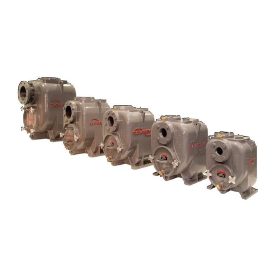
Type MPT
Centrifugal Pumps
USER INSTRUCTIONS:
INSTALLATION, OPERATION, MAINTENANCE
PCN=85392699 07-09 (E)
These instructions must be read prior to installing,
operating, using and maintaining this equipment.
MPT USER INSTRUCTIONS ENGLISH 85392699 06-09
1of 41
®
Advertisement
Table of Contents

Related Manuals for Flowserve MPT 20


Summary of Contents for Flowserve MPT 20
- Page 1 MPT USER INSTRUCTIONS ENGLISH 85392699 06-09 ® ПромХимТех - официальный дистрибьютор и сервис-партнер www.promhimtech.ru zakaz@promhimtech.ru 8 800 250 0154 ® Pump Division Type MPT Centrifugal Pumps USER INSTRUCTIONS: INSTALLATION, OPERATION, MAINTENANCE PCN=85392699 07-09 (E) These instructions must be read prior to installing, operating, using and maintaining this equipment.
- Page 2 MPT USER INSTRUCTIONS ENGLISH 85392699 06-09 ® 3.3.6 Temperature limitations ......15 CONTENTS Page 4 INSTALLATION............15 4.1 Location ............15 CONTENTS ............... 2 4.2 Foundation............15 1 INTRODUCTION AND SAFETY ......4 4.2.1 Install pump units ........15 1.1 General ............4 4.2.2 Mount baseplate........15 1.2 CE marking and approvals......
-
Page 3: Table Of Contents
6.4 Dismantling ........... 20 10.2 Change notes ..........37 6.4.1 General ..........20 6.4.2 Dismantling the pump ......20 6.4.3 Genuine Flowserve parts...... 20 6.4.4 Part numbers and identification .... 21 6.4.5 Replacing coupling parts ...... 21 6.4.6 Complete disassembly......21 6.5 Examination of parts ........ - Page 4 The instructions may not considered to be misuse. Damage or failure caused take into account local regulations; ensure such by misuse is not covered by Flowserve’s warranty. In regulations are observed by all, including those addition, any modification of Flowserve products or installing the product.
- Page 5 MPT USER INSTRUCTIONS ENGLISH 85392699 06-09 ® 1.6 Safety NEVER DO MAINTENANCE WORK WHEN THE UNIT IS CONNECTED TO POWER 1.6.1 Summary of safety markings (Lock out.) These User Instructions contain specific safety markings where non-observance of an instruction would DRAIN THE PUMP AND ISOLATE PIPING cause hazards.
- Page 6 THE DISCHARGE VALVE CLOSED (Unless otherwise instructed at a specific point in the Where Flowserve has supplied only the bare shaft pump, the Ex rating applies only to the pump. The User Instructions.) party responsible for assembling the pump set shall...
- Page 7 40 ° C (104 ° F); refe r be made and dirt removed from areas around close to Flowserve for higher ambient temperatures. clearances, bearing housings, and motors. The surface temperature on the pump is influenced by Additional requirements for self-priming the temperature of the liquid handled.
- Page 8 MPT USER INSTRUCTIONS ENGLISH 85392699 06-09 ® In addition, it is essential to make sure that seal 1.6.4.7 Maintenance of the centrifugal pump to chambers, auxiliary shaft seal systems and any heating avoid a hazard and cooling systems are properly filled. CORRECT MAINTENANCE IS REQUIRED TO AVOID POTENTIAL HAZARDS WHICH GIVE A If the operation of the system can not avoid this...
- Page 9 MPT USER INSTRUCTIONS ENGLISH 85392699 06-09 ® 1.7 Safety Labels 1.7.1 Nameplates For details of nameplate, see the Declaration of Conformity and section 3. 1.7.2 Warning labels & tags Page 9 of 41...
- Page 10 Consult Flowserve or a emitted sound. You may have already specified a noise specialist if assistance is required in combining limiting noise level when the equipment was ordered, the values.
- Page 11 Any shortage and/or damage must be reported immediately to Flowserve Pump Division and must be received in writing within ten days of receipt of the equipment. Later claims cannot be accepted.
- Page 12 Exposed shafts are taped with Polywrap 3.1 General • Flange covers are secured to both the suction The Flowserve MPT single stage pump has a back and discharge flanges or face. pull-out rotating assembly with suction and • In some cases with assemblies ordered with...
- Page 13 MPT USER INSTRUCTIONS ENGLISH 85392699 06-09 ® bearing housing allowing the pump to be shut down in the event of a seal failure – indicated by a sudden 3.2 Design of major parts drop in oil level or product showing in the oil. A vent is also fitted at the top of the housing to maintain 3.2.1 Pump casing even atmospheric pressure in the oil chamber.
- Page 14 MPT USER INSTRUCTIONS ENGLISH 85392699 06-09 ® If the driver is an internal combustion engine which has not been supplied by Flowserve, a torsional analysis must be undertaken by the supplier to 3.3 Performance and operating limits select the correct type of coupling in order to avoid shaft failure.
- Page 15 • Pump/Baseplate should not be used as pipe anchor. Expansion joints must be properly tied • If in doubt, contact Flowserve for information 3.3.4 Pump lubricant data ambient temperature limits – see motor nameplate Pump bearings and mechanical seals are oil for details.
- Page 16 Fabricated steel and cast iron base plates should be filled with grout. If in any doubt, please contact your nearest Flowserve service center for advice. FINISHED GROUT LEAVE TOP OF FOUNDATION ROUGH.
- Page 17 The Air Release pump flange Valve’s function is to vent air from the pump during the priming cycle. Flowserve Air Release Valves 4.5.3 Inlet pipe are available. The inlet pipe should be one or two sizes larger than the pump inlet bore and pipe bends should be as large a radius as possible.
- Page 18 5.1.1.1 Bearings and mechanical seals 4.6.3 Emergency stopping Pump bearings and mechanical seals are not A device to provide emergency stopping shall lubricated by Flowserve. See section 6.2 for oil chamber filling instructions. be fitted. • Bearing housing requires approx.
- Page 19 Refer to seconds. Flowserve. 5.4.2 Stop the pump 5.2.4 Correct rotation Priming accomplished, correct rotation established, 5.4.3 Prolonged shutdowns and with suction valve wide open, start the pump.
-
Page 20: Maintenance Schedule
Any sudden change in oil level should be Before dismantling the pump for overhaul, investigated without delay. A rise in bearing ensure genuine Flowserve replacement parts housing oil level, together with a drop in the seal are available. chamber oil level, indicates a secondary seal failure allowing oil leakage from the seal chamber to the bearing housing. -
Page 21: Part Numbers And Identification
MPT USER INSTRUCTIONS ENGLISH 85392699 06-09 ® • Press or drive shaft, complete with bearings, 6.4.4 Part numbers and identification Refer to section drawing for part numbers and from bearing housing in the direction of the identification. coupling end of the shaft •... -
Page 22: Bearings
Lightly oil seal scoring and O-rings for any obvious damage. If in rotating assembly and carefully slide over shaft doubt either replace or return seal to Flowserve to seat against stationary service center for inspection. • Fit inboard stationary face holder in recess in seal chamber and carefully fit stationary face 6.6 Assembly... -
Page 23: Back Pull-Out Assembly/Case
• Check all fasteners and plugs for tightness 6.7 Spare Parts 6.7.1 Ordering of spares Flowserve keeps records of all pumps that have been supplied. When ordering spares the following information should be quoted: (1) Pump serial and service number(s) - Page 24 MPT USER INSTRUCTIONS ENGLISH 85392699 06-09 ® Page left intentionally blank 24 of 41...
-
Page 25: Faults; Causes And Remedies
Throttle at discharge valve or ask head. Flowserve if the impeller can be trimmed Specific gravity of liquid different from design. Consult Flowserve Viscosity of liquid differs from design. Consult Flowserve Operation at very low capacity. Measure value and check minimum permitted Operation at high capacity. - Page 26 If alignment satisfactory check bearings for excessive wear Impeller out of balance resulting in vibration. Check and consult Flowserve Abrasive solids in liquid pumped. Check and consult Flowserve Mechanical seal was run dry. Check mechanical seal condition and...
-
Page 27: Parts List And Drawings
MPT USER INSTRUCTIONS ENGLISH 85392699 06-09 ® 8 PARTS LIST AND DRAWINGS 8.1 Sectional Arrangement and Parts List Drawings – MODEL 20 27 of 41... - Page 28 MPT USER INSTRUCTIONS ENGLISH 85392699 06-09 ® ITEM DESCRIPTION No. OF DRG. No. MATERIAL CCN No. 7000 INSTRUCTION MANUAL PAPER 85392699 6821 DRIVE SCREWS (NAMEPLATE) 122A2R37 95330452 9322-3 WARNING TAG - ALIGNMENT 9323 DECAL - PRIMING 9322-0 NAMEPLATE AY51851A 78800505 ABOVE ITEMS NOT SHOWN ON DRAWING SPARES ITEM...
-
Page 29: Sectional Arrangement And Parts List Drawings - Model 30
MPT USER INSTRUCTIONS ENGLISH 85392699 06-09 ® 8.2 Sectional Arrangement and Parts List Drawings – MODEL 30 29 of 41... - Page 30 MPT USER INSTRUCTIONS ENGLISH 85392699 06-09 ® ITEM DESCRIPTION No. OF DRG. No. MATERIAL CCN No. 7000 INSTRUCTION MANUAL PAPER 85392699 6821 DRIVE SCREWS (NAMEPLATE) 122A2R37 95330452 9322-3 WARNING TAG - ALIGNMENT 9323 DECAL - PRIMING 9322-0 NAMEPLATE AY51851A 78800505 ABOVE ITEMS NOT SHOWN ON DRAWING SPARES ITEM...
-
Page 31: Sectional Arrangement And Parts List Drawings - Model 40
MPT USER INSTRUCTIONS ENGLISH 85392699 06-09 ® 8.3 Sectional Arrangement and Parts List Drawings – MODEL 40 31 of 41... - Page 32 MPT USER INSTRUCTIONS ENGLISH 85392699 06-09 ® ITEM DESCRIPTION No. OF DRG. No. MATERIAL CCN No. 7000 INSTRUCTION MANUAL PAPER 85392699 6821 DRIVE SCREWS (NAMEPLATE) 122A2R37 95330452 9322-3 WARNING TAG - ALIGNMENT 9323 DECAL - PRIMING 9322-0 NAMEPLATE AY51851A 78800505 ABOVE ITEMS NOT SHOWN ON DRAWING SPARES ITEM...
- Page 33 MPT USER INSTRUCTIONS ENGLISH 85392699 06-09 ® 8.4 Sectional Arrangement and Parts List Drawings – MODEL 60 33 of 41...
- Page 34 MPT USER INSTRUCTIONS ENGLISH 85392699 06-09 ® ITEM DESCRIPTION No. OF DRG. No. MATERIAL CCN No. 7000 INSTRUCTION MANUAL PAPER 85392699 6821 DRIVE SCREWS (NAMEPLATE) 122A2R37 95330452 9322-3 WARNING TAG - ALIGNMENT 9323 DECAL - PRIMING 9322-0 NAMEPLATE AY51851A 78800505 ABOVE ITEMS NOT SHOWN ON DRAWING SPARES ITEM...
-
Page 35: Sectional Arrangement And Parts List Drawings - Model 80
MPT USER INSTRUCTIONS ENGLISH 85392699 06-09 ® 8.5 Sectional Arrangement and Parts List Drawings – MODEL 80 35 of 41... - Page 36 MPT USER INSTRUCTIONS ENGLISH 85392699 06-09 ® ITEM DESCRIPTION No. OF DRG. No. MATERIAL CCN No. 7000 INSTRUCTION MANUAL PAPER 85392699 6821 DRIVE SCREWS (NAMEPLATE) 122A2R37 95330452 9322-3 WARNING TAG - ALIGNMENT 9323 DECAL - PRIMING 9322-0 NAMEPLATE AY51851A 78800505 ABOVE ITEMS NOT SHOWN ON DRAWING SPARES ITEM...
-
Page 37: Certification
10.2 Change notes If any changes, agreed with Flowserve Pump Division, are made to the product after its supply, a record of the details should be maintained with these User Instructions. - Page 38 MPT USER INSTRUCTIONS ENGLISH 85392699 06-09 ® NOTES 38 of 41...
- Page 39 MPT USER INSTRUCTIONS ENGLISH 85392699 06-09 ® NOTES 39 of 41...
- Page 40 MPT USER INSTRUCTIONS ENGLISH 85392699 06-09 ® NOTES 40 of 41...
- Page 41 Telephone: +65 775 3003 Telephone: +44 (0)1372 463 700 Fax: +65 779 4607 Fax: +44 (0)1372 460 190 Visit our web site at: www.flowserve.com Your Flowserve factory contact: Your local Flowserve representative: Flowserve Pump Division 3900 Cook Boulevard Chesapeake, VA 23323-1626 USA...
Need help?
Do you have a question about the MPT 20 and is the answer not in the manual?
Questions and answers