
Subscribe to Our Youtube Channel
Related Manuals for AKO 16526A


Summary of Contents for AKO 16526A
- Page 1 3516526A02 Ed. 01 AKO-16526A Advanced temperature electronic expansion controller for cold room store User manual...
-
Page 2: Table Of Contents
Only qualified personnel may install the product or provide technical support. This product has been developed for use in the applications described in the manual. AKO Electromecánica does not guarantee its operation in any use not foreseen in this document and accepts no liability in the case of damage of any type which may result from incorrect use, config- uration, installation or commissioning. -
Page 3: Warnings
-From -40 °C to +20 °C, if the NTC sensor is extended to 1000 m with at least a 0.5 mm2 cable, the maximum deviation will be 0.25 °C (cable for sensor extension ref. AKO-15586. Earth the cable mesh at one end only). -
Page 4: Presentation
3516526A02 Ed. 01 Presentation The AKO-16526A advanced controller for cold room stores has a SELFDRIVE operating mode that automatically controls (without parametrisation) the fans and adaptively minimises defrosts to optimise the performance of the cold room store: maximising time in set point and minimising costs linked to energy consumption and wear of components. -
Page 5: Description
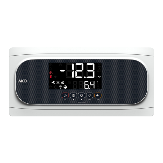
3516526A02 Ed. 01 Description 1: Display 2: Keypad Constant: Stand-By Mode activated. Regulation Constant: The SELFDRIVE mode is active. is paused. Flashing: An error has been detected in SELF- Flashing: Controlled stop process for the regu- DRIVE mode. To view it, press the key. lation in progress. - Page 6 3516526A02 Ed. 01 Keypad Press and hold for 3 seconds to activate/deactivate the Stand-By mode. In this mode, regulation is paused and the m icon is displayed.. In the programming menu, it exits the parameter without saving changes and returns to the previous level, or exits programming.
-
Page 7: Installation
3516526A02 Ed. 01 Installation - Remove the bezels (1) - Make a 1/4 turn of the screws (2) anti-clockwise and open the door (3). - Install the necessary glands (4 / 5) by drilling holes in the points indicated on the box. - Mark and make the holes in the wall with the aid of the template included. - Page 8 3516526A02 Ed. 01 Installation of the probes To achieve maximum performance from the advanced controller, correct installation of the probes is key as they are responsible for calculating the evaporator’s thermal transfer coefficient, evaluating the start and end of the defrosts and diagnosing problems in the evaporator.
-
Page 9: Wiring
3516526A02 Ed. 01 Wiring Always disconnect the power supply to do the wiring. The probes and their cables must NEVER be installed in a conduit together with power, control or power supply cables. For disconnection, the power supply circuit must be equipped with at least a 2 A, 230 V switch, located near the device. -
Page 10: Initial Configuration
3516526A02 Ed. 01 Initial configuration The AKO-16526 controller can be adapted to different types of installation according to the different options chosen in the set-up wizard. Before completing the wiring, make sure you are familiar with the details of the installation in order to configure it correctly. -
Page 11: Superheating Set Point
3516526A02 Ed. 01 Superheating SET POINT Enter the desired optimum superheating value. Assistant The first time the unit receives the power supply, it will enter into ASSISTANT mode. The display will show the message In{ flashing at 0. The buttons and change the value, the SET button accepts the value and moves on to the next step. - Page 12 3516526A02 Ed. 01 Step 3: Define the type of refrigerant gas used. u02=0 u02=1 u02=2 R404A R134A R407A u02=3 R407F u02=4 R410A u02=5 R450A u02=6 u02=7 u02=8 R513A R744 R449A / / SET u02=9 u02=10 u02=11 R290 R448A u02=12 R1234ze u02=13 u02=14 R717...
-
Page 13: Operation
3516526A02 Ed. 01 Step 11: Select the superheating set point (See page 18) Step 12: Set all other parameters to default? dFP=0 No, the other parameters do not need to be changed. / / SET dFP=1 Yes, set all other parameters to their default values. This option only appears if this is not the first time the set-up wizard has been run. - Page 14 3516526A02 Ed. 01 Severe external alarm activated (by digital input) (See page 28). Activates the alarm relay and the audible alarm. Defrost time-out alert. The time set in d1 has been exceeded (See page 30). Activates the alarm relay and the audible alarm. HACCP alarm.
- Page 15 3516526A02 Ed. 01 Calibration ongoing, therefore, avoid, as far as possible, opening the cold room during the process. For more information, s(See page 16). Flashing light with temperature: Configuration has been changed from 1 to 2 evaporators or vice versa. SELFDRIVE mode alert messages (Only shown by pressing the ...
-
Page 16: Selfdrive Mode
3516526A02 Ed. 01 SELFDRIVE mode If the SELFDRIVE mode is activated (default configuration), the device periodically evaluates the evap- orator’s heat transfer, managing the available resources to maximise it. The defrosts are minimised, adapting to the changing conditions of the cold room, reducing heat input into the refrigerated space, thermal stress in the evaporator and energy consumption. -
Page 17: Cold Regulation
3516526A02 Ed. 01 Cold regulation Solenoid control (COOL Relay) SP+C1 If u00=0 is selected in the wizard, coolant production is regulated by opening/closing the solenoid valve, which sends liquid to the thermostatic expansion valve. If u00=1 is selected in the wizard, coolant production is regulated by controlling the opening and Solenoid closing of the expansion valve (PWM control). - Page 18 A low superheat allows for better evaporator efficiency, but too low a value may cause liquid to enter the compres- sors because the liquid in the evaporator is not completely evaporated. The AKO-16526 provides stable superheat regulation and a fast response to pressure or load fluctuations, thus ensuring a high level of system safety.
- Page 19 3516526A02 Ed. 01 Pump down function This function foresees problems in the compressor caused by movements of coolant, using a stop/start technique for the installation, controlled via the liquid solenoid, the low pressure switch and the compressor itself. This function is only available for Inl 2, 5, and 7 and requires the connection of a low pressure switch in digital input 1.
- Page 20 3516526A02 Ed. 01 Regulation of cold with two temperature probes (S1 + S3) This requires configuration of input D2/S4 as a second cold room store temperature probe (l120=10). The device regulates the temperature of the cold room store taking into account the reading of both probes. Using parameter C25, the influence of probe S3 is determined in the settings.
-
Page 21: Compressor Protection Timing
Point change (I10 or I20=4). Activation through this method cancels any other activation and can only be deactivated using the same method. By means of the AKONet application. This requires the device to be connected to a Modbus network (See page 41). By means of the CAMM module and the AKO CAMM tool application. EXAMPLE: (SP+C12)+C1... -
Page 22: Door Management
3516526A02 Ed. 01 Door management Standard operating mode (CE=0) Door management allows for the installation's behaviour to be controlled, should the cold room door open through parameters C22 and C23. Parameter C22 defines whether cold production should be stopped if the door opens. If C22=1, when the door opens, the fans stop and, 15 seconds later, the solenoid closes (COOL relay). -
Page 23: Defrost
3516526A02 Ed. 01 Defrost Types of defrost There are 5 possible defrost types, depending on the option selected in the wizard (Inl): Electric (InI=1, 2 and 3) (d7=0) Defrost is performed through electrical resistors, supplying the evaporator with heat. The operation of fans in this mode depends on parameter F3;... - Page 24 3516526A02 Ed. 01 Control of defrost in standard mode (CE=0) Max. d1 DRIP TIME DEFROST COLD REGULATION COLD REGULATION DEFROST FAN START-UP DELAY “DEF” MESSAGE SP+C1 Defrost start Defrost will start if: • The time programmed in parameter d0 has elapsed since the start of the last defrost. •...
- Page 25 3516526A02 Ed. 01 Control of defrost in SELFDRIVE mode (CE=1) Defrosts in SELFDRIVE mode are not programmed, but rather the device evaluates the operation of the cold room and manages defrosts depending on the needs of the installation. If a drop in the performance of the cold room is detected due to formation of ice in the evaporator, defrost is activated and it is supervised until its completion.
- Page 26 3516526A02 Ed. 01 Other defrost parameters (They have an effect in standard and SELFDRIVE mode) Drip time It is set by parameter d9 and defines the time added at the end of defrost to allow the evacuation of the remaining defrost water from the evaporator, during which time there is no cooling regulation.
-
Page 27: Management Of The Drainage Resistor
3516526A02 Ed. 01 Other parameters Using parameter d5, you can configure whether the unit performs a defrost (d5=1) or not (d5=0) when it receives power (first start-up or after a power supply failure). Should the option YES (d5=1) be selected, defrost will begin once the delay time defined in d6 has elapsed. -
Page 28: Alarms
3516526A02 Ed. 01 Alarms The device warns the user through an on-screen message as to activation of a relay (if a relay has been set as an alarm) and a sound alarm when the criteria programmed in the parameters are met. Maximum / minimum temperature alarm It shows the message “AK”... - Page 29 3516526A02 Ed. 01 HACCP alarm The alarm is activated should situations be detected which could endanger the integrity of the products stored in the cold room. If the temperature of the cold room is higher than that defined in parameter h1 for a length of time exceeding that defined in parameter h2, the alarm activates, displaying the message HCP on screen.
-
Page 30: Alerts
3516526A02 Ed. 01 Alarm delays These delays prevent certain alarms from being shown, to allow the installation to recover its normal operation after certain events. • Delays in start-up (A3): This delays the activation of the temperature alarms upon receiving power (at start- up or after a power supply failure) or when exiting Stand-by mode. -
Page 31: Light Control
3516526A02 Ed. 01 Light control Relay AUX 1 or AUX 2 must be configured as “Light” (o00, o10 or o20=2). Switching the lights on or off is controlled using: • The LIGHT push-button: One press switches the lights on or off. •... - Page 32 3516526A02 Ed. 01 AUX 3 relay • Deactivated (o20=0): Does not carry out any function. • Alarm (o20=1): This activates the relay every time an alarm occurs (See page 28) • Light (o20=2): This regulates the operation of cold room light (See page 31). •...
-
Page 33: Configuration
3516526A02 Ed. 01 Configuration Condensed programming menu This allows for the most-used parameters to be quickly configured. Press the SET key for 3 seconds to access it. Condensed programming menu OUT OF PROGRAMMING PROGRAMMING 20 s Temperature Values Parameters indicator Change value Change... -
Page 34: Extended Programming Menu
3516526A02 Ed. 01 Extended programming menu Use the extended programming menu to configure all of the unit’s parameters in order to adapt it to your installation requirements. Press the SET key for 6 seconds to access it. IMPORTANT: If the password function has been configured as a keypad lock (b10=2), or as an access to parameters block (b10=1), you will be requested to enter the password programmed in PAS when attempting to access either of the two functions. -
Page 35: Parameters
3516526A02 Ed. 01 Parameters Regulation and control Description Values Min. Def. Max. SP Temperature setting (Set Point) ºC/ºF -50 0.0 99 CE SELFDRIVE Mode 0=Deactivated 1= Activated C0 Sensor 1 calibration (Offset) ºC/ºF -4.0 0.0 4.0 C1 Sensor 1 differential (Hysteresis) ºC/ºF 1.0 2.0 20.0 Set point top locking... - Page 36 3516526A02 Ed. 01 Defrost Description Values Min. Def. Max. d0 Defrost frequency (time between 2 starts) d1 Maximum defrost duration (0=defrost deactivated) min. Type of message during the defrost: 0=Sign of the real temperature; 1=Sign of the temperature at the start of the defrost; 2=Sample of the dEF message Maximum message duration min.
- Page 37 3516526A02 Ed. 01 Expansion valve Description Values Min. Def. Max. Valve type: 1=PWM-type EEV 2=Stepper-type EEV SH Superheating set point Refrigerant gas type: 0= R-404A, 1= R-134A, 2= R-407A, 3= R-407F, 4= R-410A, 5= R-450A, 6= R-513A, 7= R-744, 8= R-449A, 9= R-290, 10= R-32, 11= R-448A, 12=R1234ze, 13=R23, 14=R717, 15=R407C, 16=R1234yf, 17=R22, 18=R454C, 19=R455A, 20=R507A, 21=R515B, 22=R452A, 23=R452B, 24=R454A u03 PWM cycle time...
- Page 38 3516526A02 Ed. 01 Alarms Description Values Min. Def. Max. A0 Configuration of the temperature alarms 0=Relative to SP 1=Absolute A1 Alarm for maximum in sensor 1 (it must be higher than the SP) ºC/ºF A2 99.0 99.0 A2 Alarm for minimum in sensor 1 (it must be lower than the SP) ºC/ºF -50 -50 A1 Delay of temperature alarms in the start-up...
- Page 39 3516526A02 Ed. 01 Basic configuration Description Values Min. Def. Max. b00 Delay of all functions on receiving power supply min. b01 Cold room light timing min. b10 Password function 0=Inactive 1=Block access to parameters 2=Lock keypad Password b20 MODBUS address Communication speed: 0=9600 bps 1=19200 bps 2=38400 bps 3=57600 bps b22 Audible alarm enabled 0= No 1=Yes...
- Page 40 3516526A02 Ed. 01 Inputs and outputs Description Values Min. Def. Max. AUX1 relay configuration: 0= Deactivated, 1= Compressor/Crankcase resist- ance, 2= Light, 3= Virtual control, 4= Alarm, 5= Door frame resistor, 6=Drainage resistor AUX2 relay configuration: 0= Deactivated, 1= Alarm, 2= Light, 3= Virtual control, 4= Defrost 2nd evaporator, 5= Door frame resistor, 6= Equal solenoid status, 7= Equal device status, 8=Drainage resistor AUX3 relay configuration: 0= Deactivated, 1= Alarms, 2= Light,...
-
Page 41: Connectivity
Once modified, the old address indicated on the plate will not be valid. AKO-5012 AKO-80039 AKO-80039 Tr-: Yellow RS-485 >25 ** Tr+: Orange GND: Black CAMRegis AKOGAS AKOControl* AKOALARM SECURE AKOControl* AKOCORE CONTRO L Terminating resistors are not required. AKO controller with communication **AKO-80024 Use if connecting more than 25 devices. -
Page 42: Technical Specifications
Resolution, adjustment and differential ......................0.1 ºC Thermometric accuracy ..........................±1 ºC Tolerance of the NTC probe at 25 ºC ......................±0.4 ºC Input for NTC probe ....................AKO-14950 / AKO-14950-8 Working ambient temperature .......................-10 ºC to 50 ºC Ambient storage temperature ......................-30 ºC to 60 ºC Protection degree ............................ - Page 43 3516526A02 Ed. 01...
- Page 44 AKO ELECTROMECÁNICA, S.A.L. Avda. Roquetes, 30-38 08812 • Sant Pere de Ribes. Barcelona • Spain Tel.: +34 902 333 145 Fax: +34 938 934 054 www.ako.com We reserve the right to supply materials slightly different to those described in our Data Sheets. Updated information in our website.
Need help?
Do you have a question about the 16526A and is the answer not in the manual?
Questions and answers