AKO -16520 User Manual
Temperature controller for cold rooms
Hide thumbs
Also See for AKO-16520:
- Quick manual (52 pages) ,
- Manual (49 pages) ,
- User manual (32 pages)

Related Manuals for AKO AKO-16520


Summary of Contents for AKO AKO-16520
- Page 1 1652H302 Ed.10 AKO-16523 AKO-16520 AKO-16523D AKO-16523P AKO-16520P AKO-16523-V AKO-16523L Temperature controller for cold rooms User manual...
-
Page 2: Table Of Contents
Only qualified personnel should install or perform technical assistance on this product. This product is designed to be used in the applications described in the product manual. AKO Electromecánica gives no guarantee of its operation in any use not foreseen in the manual, and is not responsible for any damage resulting from improper use, configuration, installation or commissioning. -
Page 3: Versions And References
-From -40 ºC to +20 °C, if the NTC probe is extended to 1000 m with at least a 0.5 mm cable, the maximum deviation will be 0.25 ºC (cable for probe extension ref. AKO-15586. Earth the cable mesh at one end only). -
Page 4: Description
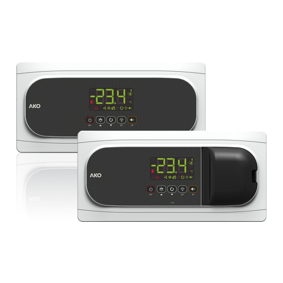
1652H302 Ed.10 Description Display CORE CORE Keypad Circuit breaker cover (Only AKO-1652xP) Indicators Constant: Stand-By Mode activated. Regulation Constant: Compressor active. is paused. Flashing: The compressor should be active but a delay or protection is preventing this. Flashing: Controlled stop process for the regulation in progress. - Page 5 1652H302 Ed.10 Keypad Pressing it for 3 seconds activates/deactivates the Stand-By mode. In this mode, regulation is paused and the m icon is displayed. In the programming menu, it exits the parameter without saving changes, returns to the previous level or exits programming.
-
Page 6: Installation
1652H302 Ed.10 Installation Ø Max. 20 mm -Remove the bezels (1) -Make a 1/4 turn of the screws (2) anti-clockwise and open the door (3). -Install the necessary glands (4 / 5) by drilling holes in the Ø Max. 25 mm points indicated on the box. -
Page 7: Wiring
Check the available options on the diagram sheet included with your device. The AKO-16523D model has a contactor which allows for the connection of three-phase defrost resistors, a three- phase compressor or three-phase fans, according to your installation’s requirements. Check how to connect it on the diagram sheet included with your device. -
Page 8: Initial Configuration (Wizard)
If the pump down function is active, a certain amount of time may elapse between starting the stand-by function and the controller stopping (see p. 11). * o00=2 in AKO-16523 / 16520 / AKO-16523-V, o00=0 in AKO-16523P / 16520P / 16523D / 16523L. -
Page 9: Operation
1652H302 Ed.10 Operation Messages MESSAGES Pump down malfunction error (stop), the time configured in parameter C20 has been exceeded (see p. 11). Only displayed on screen. Pump down malfunction error (start-up), the time configured in parameter C19 has been exceeded (see p. 11). Only displayed on screen. - Page 10 1652H302 Ed.10 Cold regulation Solenoid control (COOL Relay) SP+C1 Cold production is regulated by means of opening / closing the solenoid valve. When the temperature in probe S1 reaches the set point (SP) value plus the probe's differential (C1), the solenoid opens and causes the temperature to drop.
- Page 11 1652H302 Ed.10 Pump down function This function foresees problems in the compressor caused by movements of coolant, using a stop/start technique for the installation, controlled via the liquid solenoid, the low pressure switch and the compressor itself. This function is only available for In{ options 2, 5, 7, 9 and 12 and requires the connection of a low pressure switch in digital input 1.
- Page 12 Ÿ By means of the AKONet application. This requires the device to be connected to a Modbus network (see p. 28). Ÿ By means of the CAMM module and the AKO CAMM tool application. EXAMPLE: Calibration of probe 1 Configuration...
- Page 13 1652H302 Ed.10 Compressor protection timing Parameter C4 allows for selection of the type of timing to be applied to protect the compressor. These delays prevent continuous compressor starts and stops. These timings affect the COOL and AUX 1 relays (if o00=1) OFF-ON (C4=0): Minimum time in OFF mode before each start-up.
- Page 14 1652H302 Ed.10 Defrost Types of defrost There are 5 possible defrost types, depending on the option selected in the wizard (Inl): Electric (InI=1, 2 and 3) (d7=0) Defrost is performed through electrical resistors, supplying the evaporator with heat. The operation of fans in this mode depends on parameter F3;...
- Page 15 1652H302 Ed.10 Reversed cycle (InI=9 y 10) (d7=3) A 4-way valve is used to invert the installation cycle, using the evaporator as a condenser to melt the ice formed. The process begins by stopping cold production (if it is active). If Pump Down is active, defrost begins once the manoeuvre is complete.
- Page 16 1652H302 Ed.10 Fan start-up delay This is established through parameter F4 and allows for the possible drops left in the evaporator to freeze before the fans activate, preventing them from being projected into the cold room. It also prevents heat being supplied to the cold room due to defrost in the evaporator.
- Page 17 1652H302 Ed.10 Other parameters Using parameter d5, you can configure whether the unit performs a defrost (d5=1) or not (d5=0) when it receives power (first start-up or after a power supply failure). Should the option YES (d5=1) be selected, defrost will begin once the delay time defined in d6 has elapsed.
- Page 18 1652H302 Ed.10 Alarms The device warns the user through an on-screen message, activation of a relay (only 5-relay devices if o10=1 or 4- relay devices if o00=4) and a sound alarm when the criteria programmed in the parameters are met. Maximum / minimum temperature alarm It shows the message “AK”...
- Page 19 1652H302 Ed.10 Open door alarm The door has been open for a longer time than defined in parameter A12, the open door alarm is activated. In order to detect the open door, configuration is required of one of the digital inputs as “door contact”...
- Page 20 1652H302 Ed.10 Alerts The device alerts the user through an on-screen message when an event occurs which requires his/her attention. However, it does not activate the sound alarm or the alarm relay (if active). Defrost finished by time alarm The message Adt is displayed when a defrost has completed due to time-out, if parameter A8=1. Pump down malfunction error (stop) The message Pd is displayed if a malfunction is detected when the installation is stopped using the pump down manoeuvre.
- Page 21 1652H302 Ed.10 Operation of the auxiliary relays Depending on the controller model, it may have 1 or 2 auxiliary relays. The function of these relays is configurable through the parameters menu. AUX 1 relay Deactivated (o00=0): It does not carry out any function. Ÿ...
-
Page 22: Configuration
1652H302 Ed.10 Configuration Condensed programming menu This allows for the most-used parameters to be quickly configured. Press the SET key for 3 seconds to access it. Condensed programming menu OUT OF IN PROGRAMMING PROGRAMMING 20 sec. Temperature Parameters Values indication 3 seg. - Page 23 1652H302 Ed.10 Extended programming menu Use the extended programming menu to configure all of the unit’s parameters in order to adapt it to your installation requirements. Press the SET key for 6 seconds to access it. IMPORTANT: If the password function has been configured as a keypad lock (b10=2), or as an access to parameters block (b10=1), you will be requested to enter the password programmed in PAS when attempting to access either of the two functions.
- Page 24 1652H302 Ed.10 Parameters Regulation and control Description Values Min. Def. Max. Temperature setting (Set Point) ºC/ºF Probe 1 calibration (Offset) ºC/ºF -20.0 20.0 Probe 1 differential (Hysteresis) ºC/ºF 20.0 Set Point top locking (it cannot be set above this value) ºC/ºF Set Point bottom locking (it cannot be set below this value) ºC/ºF...
- Page 25 1652H302 Ed.10 Defrost Description Values Min. Def. Max. Defrost frequency (Time between 2 starts) Min. Maximum defrost duration (0=defrost deactivated) Type of message during the defrost: 0=Displays the real temperature; 1=Displays the temperature at the start of the defrost; 2=Displays the dEF message Maximum duration of the message Min.
- Page 26 1652H302 Ed.10 Alarms Description Values Min. Def. Max. Configuration of the temperature alarms 0=Relative to SP 1=Absolute Alarm for maximum in probe 1 (It should be higher than the SP) ºC/ºF Alarm for minimum in probe 1 (It should be lower than the SP) ºC/ºF Delay of temperature alarms in the start-up Min.
- Page 27 Configuration of relay AUX1 0=Deactivated 1=Compressor/Resistor sump † 2=Light 3=Virtual control =Alarm ( AKO-16523 / 16523-V / 16520 Only) Configuration of relay AUX2 (Not available in AKO-16523 / 16523-V / 16520) =Deactivated 1=Alarm 2=Light 3=Virtual control 4=Door frame resistance 5=Defrost 2° evaporator...
-
Page 28: Connectivity
Once modified, the old address indicated on the plate will not be valid. AKO-5012 AKO-80039 AKO-80039 Tr-: Yellow RS-485 >25 ** Tr+: Orange GND: Black CAMRegis AKOGAS AKOControl* AKOALARM SECURE AKOControl* AKOCORE CONTROL Terminating resistors are not required. *AKO controller with communication **AKO-80024 Use if connecting more than 25 units... -
Page 29: Technical Specifications
1652H302 Ed.10 Technical specifications Power supply AKO-16523 / 16523P / 16523D / 16523-V / 16523L....230 V~ ± 10%, 50 Hz ± 5% AKO-16520 / 16520P............120 V ~ + 8% - 12%, 50 Hz ± 5% Maximum input power in the operation ......................6.3 VA Maximum nominal current..........................15 A... -
Page 30: Accessories
1652H302 Ed.10 Accessories AKO-58500 CAMM Module Together with the application for mobile devices, this module provides the unit with multiple functionalities: - Data logging - Activity summaries - Logging of configuration changes - Logging of events and alerts - Remote configuration... - Page 31 1652H302 Ed.10...
- Page 32 AKO ELECTROMECÁNICA , S.A.L. Avda. Roquetes, 30-38 08812 • Sant Pere de Ribes. Barcelona • Spain. www.ako.com We reserve the right to supply materials that might vary slightly to those described in our Technical Sheets. Updated information is available on our website.
Need help?
Do you have a question about the AKO-16520 and is the answer not in the manual?
Questions and answers