Table of Contents
Advertisement
Available languages
Available languages
D141H232 Ed.03
GB
Installation instructions
AKO-D14120 AKO-D14123
AKO-D14023 AKO-D14023-C AKO-D14024
AKO-D14124 AKO-D14125
3- Wiring
The probe and its cable should NEVER be installed in the same conduit as power, control or supply cables.
AKO-D14123, AKO-D14124, AKO-D14125
I max.:
Mode: HEAT
16 A
16 A
L N
(P0=1)
1
2
3
4
5
6
230 V~
50/60 Hz
Probe 1
RES.
AKO-D14023, AKO-D14024
1
2
3
4
5
6
230 V~
50/60 Hz
Probe 1
4- Operation
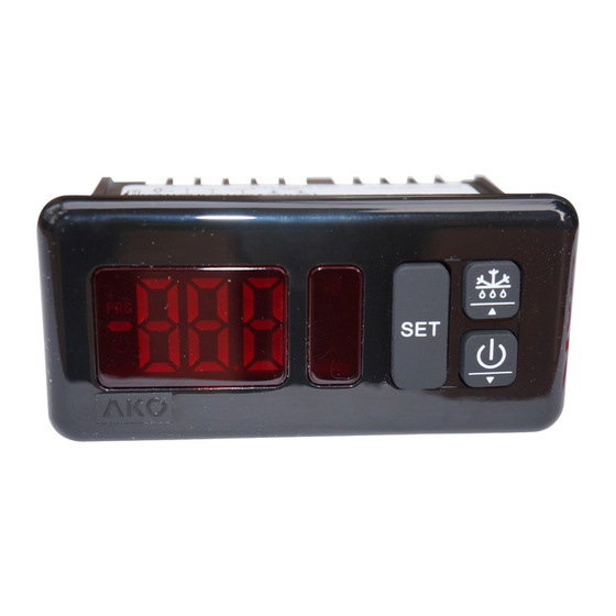
3 key equipment
Display
Program Mode
COOL relay ON (P0=0)
SET
Standby
RES relay active (P0=1)
mode
SET key
Press for 5 seconds to modify the set point (SP).
Press for 10 seconds to go to the programming menu.
In the programming menu, go to the level displayed or accept
the new value while setting a parameter.
N
H
Up key
/
Pressing for 5 seconds starts/stops defrosting.
In programming menu, allows you to scroll through the
various levels or, during the setting of a parameter, to change
the value.
Q
m
Down key
/
Pressing for 5 seconds activates Standby mode, pressing for 2
seconds returns the equipment to normal mode. In Standby
mode, the equipment performs no actions and only the m
indicator is displayed on the screen.
In programming menu, allows you to scroll through the
various levels or, during the setting of a parameter, to change
the value.
1- Warnings
-Using the equipment without following the manufacturer's
instructions may affect the device's safety requirements. To ensure
that the device operates correctly, only probes supplied by AKO
should be used.
-The unit must be installed in a location protected from vibrations,
water and corrosive gases, where the ambient temperature does
not exceed that shown in the technical data.
-To ensure a correct reading, the probe must be situated in a location
without any external heat influences except for the temperature
which is being measured or controlled.
-The power supply circuit must be provided with a main switch rated
at at least 2 A, 230 V, located close to the equipment. The cables will
enter through the back and should be type H05VV-F or H05V-K.
-The gauge will depend on local regulations, but should in no case be
2
less than 1 mm .
-Connecting wires for the relay contacts should be sized 2.5 mm .
-Between -40 ºC and +20 ºC, if the probe NTC is prolonged till 1.000 m
with a mínimum of cable 0,5 mm², the maximum deviation will be of
0,25 ºC (extension cable for probe ref. AKO-15586)
AKO-D14012
NOTE: Equipment not compatible with AKO-14917 (external
communication module) and AKO-14918 (programming key)
Mode: COLD
16 A
(P0=0)
1
2
3
4
5
6
230 V~
50/60 Hz
Probe 1
COOL
AKO-D14012
1
2
3
4
5
6
_ ~
12 V
Probe 1
_ ~
24 V
1 key equipment
Program Mode
Keyboard
Standby
mode
m
SET key /
Pressing for 5 seconds activates Standby mode, pressing for 2
seconds returns the equipment to normal mode. In Standby mode,
the equipment performs no actions and only the m indicator is
displayed on the screen.
Pressing for 10 seconds goes to the programming menu.
Pressing for 5 seconds in the programming menu goes to the level
displayed on the screen or, during the setting of a parameter, accepts
the new value.
In the programming menu, a short press allows you to scroll
through the various levels or, during the setting of a parameter, to
increment the value. When upper limit is reached, it will start
again from the lower limit.
5- Start-up
(Only 3 key models)
On power-up, the equipment will start up in Wizard mode (P3 / 1
flashing), press N or Q to select the most appropriate
application and press SET.
1: Multipurpose
4: Fresh fish
7: AC
The wizard will configure the parameters of the equipment for the
chosen application (see table "Default settings by application").
I max.:
16 A
Mode: HEAT
16 A
L N
(P0=1)
1
2
120 V~
50/60 Hz
Modbus
AKO-D14023-C
12
13
14
15
1
2
3
4
5
90-260 V~
50/60 Hz
Probe 1
Display
SET
SET key / m
2: Frozen
3: Fruits and vegetables
5: Soft Drinks
6: Bottle racks
8: Heat / Incubators
2- Installation
2
AKO-D14120
I max.:
Mode: COLD
16 A
L N
(P0=0)
3
4
5
6
120 V~
50/60 Hz
Probe 1
RES.
6
7
8
9
10 11
5.1- Access to set point and programming
3 key equipment
5 sec.
Temperature
Release SET
Indication
the set point
1 key equipment
5 sec.
SET
Temperature
Release SET
Indication
7 1 m m
I max.:
16 A
16 A
L N
1
2
3
4
5
6
Probe 1
COOL
10 sec.
t
Release SET
to access
to access
programming
10 sec.
t
Release SET
to go to
to access
Stand-by
programming
Advertisement
Table of Contents

Related Manuals for AKO AKO-D14120


Summary of Contents for AKO AKO-D14120
- Page 1 2- Installation -Using the equipment without following the manufacturer's D141H232 Ed.03 instructions may affect the device's safety requirements. To ensure that the device operates correctly, only probes supplied by AKO 7 1 m m should be used. Installation instructions -The unit must be installed in a location protected from vibrations, water and corrosive gases, where the ambient temperature does not exceed that shown in the technical data.
-
Page 2: Technical Specifications
Time relay OFF in case of fault of probe 1 AKO-D14120......120 V~ +8 % - 12 % 50/60 Hz 4 VA ·... - Page 3 Ne pas respecter les instructions du fabricant lors de l'utilisation de D141H233 Ed.03 l'équipement peut mettre en danger la sécurité de l'appareil. Pour le bon fonctionnement de l’appareil, seules les sondes fournies par AKO doivent 7 1 m m être utilisées.
- Page 4 (Si C7=0 et C8=0, le relais sera toujours sur OFF déconnecté) AKO-D14120......120 V~ +8 % - 12 % 50/60 Hz 4 VA Temps de relais sur OFF en cas de défaut de la sonde 1...
- Page 5 ATENCIÓN: Equipo no compatible con AKO-14917 (Módulo AKO-D14023 AKO-D14023-C AKO-D14024 AKO-D14124 AKO-D14125 externo de comunicación) y AKO-14918 (Llave de programación) 3- Conexionado La sonda y su cable NUNCA deben instalarse en una conducción junto con cables de potencia, control o alimentación.
- Page 6 (Si C8=0 y C7¹0, el relé estará siempre en ON conectado) AKO-D14120......120 V~ +8 % - 12 % 50/60 Hz 4 VA ·...
Need help?
Do you have a question about the AKO-D14120 and is the answer not in the manual?
Questions and answers