Advertisement
Quick Links
D144H23P2 Ed.03
GB
Installation instructions
AKO-D14423-P
AKO-D14423-P-RC
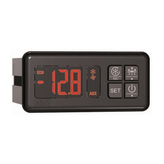
3- Installation
7 1 m m
4-
Operation
ESC key / %
Press for 5 seconds to start/stop Fast Freezing mode (rapid
cooling).
In the programming menu, exit without saving parameter,
return to previous level or exit programming.
SET key
Press for 5 seconds to modify the set point (SP) (Set Point).
Press for 10 seconds to go to the programming menu.
In the programming menu, go to the level displayed or accept
the new value while setting a parameter.
Up key N / H
Pressing for 5 seconds starts/stops defrosting.
The programming menu, allows you to scroll through the
various levels or, during the setting of a parameter, to change
the value.
Down key Q / m
Pressing for 5 seconds activates Standby mode, pressing for 2
seconds returns the equipment to normal mode. In Standby
mode, the equipment performs no actions and only the
indicator is displayed on the screen m.
The programming menu, allows you to scroll through the
various levels or, during the setting of a parameter, to change
the value.
5- Start-up
On power-up, the equipment will start up in Wizard mode
(P3 / 1 flashing), press N or Q to select the most
appropriate application and press SET.
1: Multipurpose 2: Frozen
3: Fruits and vegetables
4: Fresh fish
5: Soft Drinks
6: Bottle racks
7: AC
The wizard will configure the parameters of the equipment for
the chosen application (see table "Default settings by
application").
WARNING: The default parameters by type of
application have been defined for the most
common applications. Check that these
parameters are suitable for your installation.
1- Warnings
-Using the equipment without following the manufacturer's instructions may affect the device's safety requirements. To ensure that
the device operates correctly, only probes supplied by AKO should be used.
-The unit must be installed in a location protected from vibrations, water and corrosive gases, where the ambient temperature does not
exceed that shown in the technical data.
-To ensure a correct reading, the probe must be situated in a location without any external heat influences except for the temperature
which is being measured or controlled.
-The power supply circuit must be provided with a main switch rated at at least 2 A, 230 V, located close to the equipment. The cables
will enter through the back and should be type H05VV-F or H05V-K.
-The gauge will depend on local regulations, but should in no case be less than 1 mm .
-Connecting wires for the relay contacts should be sized 2.5 mm .
-Between -40 ºC and +20 ºC, if the probe NTC is prolonged till 1.000 m with a mínimum of cable 0,5 mm², the maximum deviation will
be of 0,25 ºC (extension cable for probe ref. AKO-15586)
NOTE: Equipment not compatible with AKO-14917 (external communication module) and AKO-14918 (programming key)
2- Wiring
The probe and its cable should NEVER be installed in the same conduit as power, control or supply cables.
AKO-D14423-P / D14423-P-RC
Modbus*
13
14
15
16
1
2
3
4
5
6
7
8
9
90-240 V~
50/60 Hz
* According to model
Access to set point and programming
5 sec.
10 sec.
SET
Temperature
Release SET
Indication
to access the
set point
Change set point (SP)
Change
Accept value
value
and exit
Current
New
Value
Value
Programming Menu (parameters)
Change
Change
menu
param.
OK
OK
SET
SET
Level 1
Level 2
Menus
Parameters
ESC
ESC
Exit Programming
Return to
Level 1
Back up one level without saving changes
ESC
DEFAULT SETTINGS BY APPLICATION (InI)
1
2
3
4
SP
-18
10
0
2
d0
4
4
4
4
d1
20
20
20
20
F0
8
0
30
8
F3
1
0
1
1
P0
0
0
0
0
2
I max.:
16 A
L N
10 11 12
AUX
AUX.
FAN
COOL
DEF
Program Mode
ECO relay
t
ON
Release SET
to access
programming
Fast Freezing
SET
mode
Standby
mode
Temperature
Indication
Change value
OK
SET
Level 3
Values
5
6
7
3
12
21
24
24
96
20
20
0
8
30
99
1
1
0
0
0
0
2
AUX Relay
AUX.
Function as per parameter P6
S1: Probe 1, temperature in the chamber or cabinet
S2/DI2: Probe 2, defrost or digital input 2
(as per P4)
S3/DI1: Probe 3, temperature of product / 2nd
defrost, or digital input 1 (as per P4)
Display
FAN relay ON
COOL relay ON (P0=0)
ESC
SET
AUX relay ON
RES relay ON (P0=1)
Lights ON (P6=3)
DEF relay ON
Keyboard
Advertisement

Related Manuals for AKO AKO-D14423-P


Summary of Contents for AKO AKO-D14423-P
- Page 1 -Between -40 ºC and +20 ºC, if the probe NTC is prolonged till 1.000 m with a mínimum of cable 0,5 mm², the maximum deviation will be of 0,25 ºC (extension cable for probe ref. AKO-15586) NOTE: Equipment not compatible with AKO-14917 (external communication module) and AKO-14918 (programming key) 2- Wiring The probe and its cable should NEVER be installed in the same conduit as power, control or supply cables.
- Page 2 Types of probe ....... . NTC AKO-149xx / PTC AKO-1558xx...
Need help?
Do you have a question about the AKO-D14423-P and is the answer not in the manual?
Questions and answers