
Related Manuals for Busch-Jaeger Busch-AudioWorld 8217 U-101


Summary of Contents for Busch-Jaeger Busch-AudioWorld 8217 U-101
- Page 1 Product manual │ 08.12.2021 Busch-AudioWorld ® 8217 U-101 Busch-Radio BTconnect DAB+ Branding -- Release 2018-01-01...
-
Page 2: Table Of Contents
Table of contents Table of contents Notes on the instruction manual ........................5 Trademarks ..............................5 Safety ................................6 Introduction ............................6 Information and symbols used ......................6 Intended use ............................7 ... - Page 3 Table of contents 9.2.8 Save favourites (favourite stations) .................... 38 9.2.9 Operating Bluetooth ® ........................39 9.2.10 Instructions and the rectification of problems for your Bluetooth operation ......... 43 9.2.11 Operating AUX ........................... 46 ...
- Page 4 Table of contents 10.6 AUX and amplifier .......................... 105 10.7 AUX and HiFi system ........................107 10.8 Playing the multimedia device via the flush-mounted radio on the HiFi system ......109 10.9 AUX and TV audio signals ......................111 ...
-
Page 5: Notes On The Instruction Manual
If you pass the device on, also pass on this manual along with it. Busch-Jaeger accepts no liability for any failure to observe the instructions in this manual. If you require additional information or have questions about the device, please contact Busch- Jaeger or visit our Internet site at: www.BUSCH-JAEGER.de... -
Page 6: Safety
However, residual hazards remain. Read and adhere to the safety instructions to prevent hazards of this kind. Busch-Jaeger accepts no liability for any failure to observe the safety instructions. Information and symbols used The following Instructions point to particular hazards involved in the use of the device or provide... -
Page 7: Intended Use
Each use not listed in Chapter 3.3 “Intended use“ on page 7 is deemed improper use and can lead to personal injury and damage to property. Busch-Jaeger is not liable for damages caused by use deemed contrary to the intended use of the device. The associated risk is borne exclusively by the user/operator. -
Page 8: Target Group / Qualifications Of Personnel
Safety Target group / Qualifications of personnel 3.5.1 Operation No special qualifications are needed to operate the device. 3.5.2 Installation, commissioning and maintenance Installation, commissioning and maintenance of the device must only be carried out by trained and properly qualified electrical installers. The electrical installer must have read and understood the manual and follow the instructions provided. -
Page 9: Safety Instructions
Safety Safety instructions Danger - Electric voltage! Electric voltage! Risk of death and fire due to electric voltage of 100 … 240 V. Dangerous currents flow through the body when coming into direct or indirect contact with live components. This can result in electric shock, burns or even death. -
Page 10: Information On Protection Of The Environment
Information on protection of the environment Information on protection of the environment Environment Consider the protection of the environment! Used electric and electronic devices must not be disposed of with domestic waste. – The device contains valuable raw materials which can be recycled. Therefore, dispose of the device at the appropriate collecting depot. -
Page 11: Setup And Function
Setup and function Setup and function Functions The device is a functional radio with various setting options and is installed flush-mounted in the wall. The device offers you the following, for example: A Bluetooth interface for music replay from mobile devices and for sending music to mobile ■... -
Page 12: Possible Combinations
Setup and function Possible combinations 8217 U-101 8223 U 8222 EB 8224 EB 8225 EB 8226 EB 8226/10 EB 8252-xxx-101 Table 1: Possible combinations Notice Connection of loudspeakers, see chapter 7.5.1 “Loudspeaker“ on page 21. Product manual 2CKA001373B5163 │12... -
Page 13: Technical Data
Technical data Technical data Designation Value Nominal voltage: 230 V AC, ±10%, 50 / 60 Hz Display Colour display ■ Visual range horizontal / vertical: +/- 80° ■ Power consumption during the idle state ECO mode: ≤ 0.4 W ■ Comfort mode: ≤... -
Page 14: Connection, Installation / Mounting
Connection, installation / mounting Connection, installation / mounting Safety Danger - Electric voltage! Risk of death due to electrical voltage of 100 … 240 V during short-circuit in the low-voltage conduit. – Low-voltage and 100 … 240 V conduits must not be installed together in a flush-mounted box! Attention! - antenna signal is too weak! If the antenna signal is too weak at the mounting location planned for the device,... -
Page 15: Mounting / Dismantling
Connection, installation / mounting Mounting / dismantling Caution! The device can sustain damage when coming into contact with hard objects! The plastic parts of the device are sensitive. – Pull the attachment off only with your hands. – Do not lever parts off with screwdrivers or similar hard objects. Hinweis Elektronische Geräte mit integriertem Schaltnetzteil können im Einzelfall Empfangsstörungen verursachen, wenn diese in unmittelbarer Nähe zum Radio... - Page 16 Connection, installation / mounting Fig. 2: Device in as-delivered state: pulling off the attachment – If the device is in its as-delivered state, pull the attachment off the flush-mounted insert with your hands. – Pull the attachment off only with your hands! –...
- Page 17 Connection, installation / mounting Fig. 4: Connecting the power supply cable 3. Connect the mains cables to the flush-mounted insert. – Both connecting terminals are screw-type terminals. – Screw-type terminals (max. 3.5 Lb-In, 0.4 Nm) – For the connection assignment, see chapter 7.4 “Electrical connection“ on page 20. Fig.
- Page 18 Connection, installation / mounting Fig. 6: Mounting the display 5. Plug the attachment together with the cover frame onto the flush-mounted insert. – Ensure that the plug-in connection on the rear side does not get jammed. – The arrow (TOP) must point upwards when plugging it. –...
- Page 19 Connection, installation / mounting Dismantling To dismantle the device, perform the following steps: Dismantling is carried out in the reverse order to mounting. Fig. 7: Loosening the plug-in terminals Loosen the plug-in terminals of the loudspeaker cables and signal lines on the flush- ■...
-
Page 20: Electrical Connection
Connection, installation / mounting Electrical connection Note An automatic circuit breaker must be available in the building installation. – Automatic circuit breaker: 110 - 230 V AC, ±10%, 50 / 60 Hz max. B16A. – Local regulations for electrical installations must be adhered to. IN/OUT Fig. -
Page 21: Multimedia Connection
Connection, installation / mounting Multimedia connection 7.5.1 Loudspeaker MONO operation IN/OUT Fig. 9: Loudspeaker connection MONO For MONO operation, the loudspeaker can be connected to the left (L+ / L-) or right (R+ / R-) connecting terminals. – Observe the polarity of the connections when connecting the loudspeakers. STEREO operation IN/OUT Fig. - Page 22 Connection, installation / mounting Bluetooth ® DAB+ 09:36 Busch-Radio Greatest Hits DAB+ 09:36 Busch-Radio Greatest Hits Fig. 11: Loudspeaker connection via Bluetooth ® More detailed information for the connection of a Bluetooth loudspeaker, see chapter 9.2.9 ® “Operating Bluetooth “ on page 39. If a Bluetooth loudspeaker is connected with the device, the internal loudspeakers of the device are deactivated.
-
Page 23: Aux (Auxiliary)
Connection, installation / mounting 7.5.2 AUX (Auxiliary) The AUX inputs or AUX outputs are analogue inputs / outputs for audio signals. External audio sources can be connected to AUX inputs. E.g. MP3-Players or the audio channel of a TV. These audio signals are then output via the loudspeakers connected to the device. For the transmission of the audio signals, amplifiers of a stereo system can be connected. - Page 24 Connection, installation / mounting DAB+ 09:36 Busch-Radio Greatest Hits Fig. 13: AUX extension Cinch Connection via communication adapter with cinch-jacks. ■ Notice Communication adapters must be assembled separately depending on the model. The necessary products are selected in the online catalogue. ...
-
Page 25: Antenna
Connection, installation / mounting 7.5.3 Antenna Fig. 14: Antenna An external antenna can be connected directly on the device. E.g. a cable antenna. – Cable antenna: Length approx. 90 cm, wire cross-section 0.5 mm² (AWG 18 – 22). Changes to the position of the cable antenna can have a serious effect on the quality of reception. -
Page 26: Commissioning
Commissioning Commissioning For this device there is no classic technical commissioning. After activating the electric power, selected areas are run through consecutively from the "Settings" area. – This setup is carried out automatically during initial commissioning or after resetting the settings (see chapter 9.3.37 “RESET (resetting to the factory settings)“... - Page 27 Commissioning After the automatic search, the device switches back to standard operation automatically and plays the first stored favourite. – If no stations are found during the automatic search, the device changes automatically into favourite "Bluetooth". In this case the Bluetooth icon on the display flashes. –...
-
Page 28: Operation
Operation Operation Operating modes The device has three operating modes. Standby Fig. 15: Standby The device is in standby. ■ – Via the "ON / OFF" button [1] you switch the device into "Standard" operation or back into "Standby" operation. Standard operation Fig. - Page 29 Operation Configuration Fig. 17: Configuration / Setup E.G Setting the alarm time ■ – see chapter 9.3 “Operation - Configuration“ on page 49. – With a long press (> approx. 2 seconds) of the "ENTER" button [4], you switch the device into"Configuration"...
-
Page 30: Normal Operation
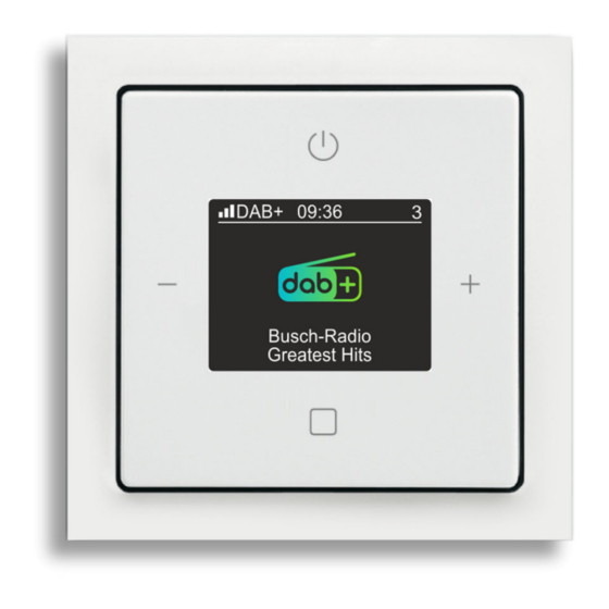
Operation Normal operation 9.2.1 Overview Fig. 18: Overview of radio display [1] Current reception quality of the selected station [2] Signal type of the reception signal Analogue (FM) ■ Digital (DAB+) ■ [3] Time / Status display [4] Favourite position of the stored radio station [5] Current radio station [6] Information about the current radio station Fig. -
Page 31: Button Assignment
Operation 9.2.2 Button assignment Fig. 20: Button assignment for operation [1] ON/OFF Switch the device into standby operation or into standard operation. ■ Sleep function (press the button for at least 2 seconds), see chapter 9.2.6 “Sleep ■ function (turn-off time)“ on page 37. [2] Minus –... -
Page 32: Adjusting The Volume
Operation 9.2.3 Adjusting the volume Fig. 21: Adjusting the volume Use the following steps to adjust the volume: 1. During normal operation press the buttons "MINUS" [2] or "PLUS" [3]. – The device adjusts the volume. – In Bluetooth mode the volume cannot be adjusted fully down. You would not hear anything from your connected multimedia device if you wish to adjust the volume from there. - Page 33 Operation Via the station search mode the stations can be preset and stored as favourites in 8 positions. – Station search mode: see chapter 9.3.11 “Menu "Stations" - "Automatic search mode DAB+"“ on page 61 ■ see chapter 9.3.12 “Menu "Stations" - "Automatic search mode for FM stations"“ on ■...
-
Page 34: Operating Alarm Clock / Snooze Function
Operation 9.2.5 Operating alarm clock / snooze function Fig. 23: Alarm call function A beep is available for the alarm or playing of the radio. The active alarm call function is shown in the display [1]. The alarm signal is shown in the display when the alarm clock starts [2]. The beep or the radio gets gradually louder. - Page 35 Operation Interrupting the alarm clock (snooze function) Start the snooze function by pressing any button of the device. – The snooze function can only be started during the signal tone. Behaviour of the alarm call function and the snooze function The behaviour of the alarm call and snooze function depends on the switching state of the device.
- Page 36 Operation The radio is switched off. ■ Case C "Beep" has been set as signal tone. ■ The alarm time has been reached. ■ Behaviour and functions: The behaviour and functions are the same as in Case A. ■ – The radio is off between the signal tones. Table 6: Alarm clock / Snooze function Case C The radio is switched off.
-
Page 37: Sleep Function (Turn-Off Time)
Operation 9.2.6 Sleep function (turn-off time) Fig. 24: Sleep timer operation By switching on the sleep function the device is automatically switched off after a preset time. This function can only be called up when the radio is switched on. The switching time of the switching function is adjusted in the settings, see chapter 9.3.31 “Menu "Settings"... -
Page 38: Display Favourites (Favourite Stations)
Operation 9.2.7 Display favourites (favourite stations) There are two ways to display favourites. Change to the following functions in the device: Move favourites, see chapter 9.3.14 “Menu "Station" - "Move favourites"“ on page 64. ■ Delete favourites, see chapter 9.3.15 “Menu "Station" - "Delete favourites"“ on page 65. ■... -
Page 39: Operating Bluetooth
Operation 9.2.9 Operating Bluetooth ® Bluetooth ® allows data transmission between devices over short distances. Your device uses this technology to receive and play or send digital music data. E.g. via smartphones or Bluetooth loudspeakers. Examples of device compilations for the use of Bluetooth ®... - Page 40 Operation Fig. 26: Bluetooth ® Use the following steps to play data on the flush-mounted radio: 1. Switch the flush-mounted radio on. – After the device is switched on, the favourite that was last listened to is displayed. 2. Press button "ENTER" [4] as often as required until you have changed to the Bluetooth favourite.
- Page 41 Operation Hearing the station of the flush-mounted radio on the external multimedia device DAB+ 09:36 Busch-Radio Greatest Hits ® Fig. 27: Send Bluetooth To play a favourite of the flush-mounted radio on an external multimedia device, the following settings must have been made: The Bluetooth mode of the flush-mounted radio must be set on "Station".
- Page 42 Operation – Depending on the external multimedia device, the connection is established automatically. If this is not the case, establish the connection from the flush-mounted radio, see chapter 9.3.17 “Menu "Bluetooth" – "Connect device"“ on page 67. 4. Play the favourite of the flush-mounted radio on the multimedia device. –...
-
Page 43: Instructions And The Rectification Of Problems For Your Bluetooth Operation
Operation 9.2.10 Instructions and the rectification of problems for your Bluetooth operation Functions / Preliminary considerations Coupling ■ – The devices are "joined" together. Each one of the other devices is stored in a list. – Only coupled devices can be connected with each other to exchange data and to play music. - Page 44 Operation Bluetooth mode of the flush-mounted radio The flush-mounted radio only displays the functions that are possible in the respective mode. Impossible functions are not visible. "Receiver" mode Coupling must come from the external device. ■ Uncoupling can be made for both devices. ■...
- Page 45 Operation Rectification of problems for Bluetooth operation If the Bluetooth icon is permanently displayed on the flush-mounted radio, the multimedia device is connected. Nothing can be heard on the flush-mounted radio. ■ – The multimedia device is currently switched off (time out not yet reached). –...
-
Page 46: Operating Aux
Operation 9.2.11 Operating AUX With the AUX function you play the music of the flush-mounted radio on an external device. E.g. a HiFi system. The music of the external device can also be played on the flush-mounted radio. For additional information about the AUX connection, see chapter 7.5.2 “AUX (Auxiliary)“ on ■... - Page 47 Operation Hearing the station of the flush-mounted radio on the external device To play a favourite of the flush-mounted radio on an external device, the following settings must have been made: The "AUX" mode of the flush-mounted radio must be set on "AUX output". ■...
-
Page 48: Voltage Failure
Operation 9.2.12 Voltage failure At an electric voltage failure all personal settings are retained. ■ The time of the device does not update itself automatically after a failure of the electric ■ voltage. – After a power failure the on the display shows 00:00. –... -
Page 49: Operation - Configuration
Operation Operation - Configuration The change to the configuration menu is only possible when the flush-mounted radio is switched on. To change to the configuration menu, perform the following steps: 1. Switch the flush-mounted radio on. 2. Press the "ENTER" button for at least 2 seconds. –... -
Page 50: Button Assignment
Operation 9.3.2 Button assignment Fig. 32: Key assignment for the configuration menu [1] ON/OFF – One level higher [2] Minus – Preceding menu item [3] Plus – Next menu item [4] ENTER – Brief press: Call up menu / confirm selection ... -
Page 51: Functions - Configuration
Operation 9.3.3 Functions - Configuration The manual settings or the start / stop of functions is carried out in the following menus. Observe also the references to the menu items mentioned in the following. Fig. 33: Alarm clock Alarm clock (1 / 5), see the chapters regarding the alarm clock from Chapter 9.3.4 “Menu "Alarm clock"... - Page 52 Operation Fig. 36: Settings Settings (4 / 5), see the chapters regarding settings from Chapter 9.3.21 “Menu "Settings" - "Language"“ on page 71 Here the device settings are carried out, e.g. language or display. ■ Fig. 37: Info Info (5 / 5), see the chapters regarding Info from Chapter 9.3.36 “Menu "Info"“ on page 89 Here the information about the device and the firmware is listed.
-
Page 53: Menu "Alarm Clock" - "Alarm Clock
Operation 9.3.4 Menu "Alarm clock" - "Alarm clock" Fig. 38: Alarm clock ON / OFF The menu is located in menu level "Alarm clock". The alarm call function is operated via this menu. Use the following steps to set, activate and deactivate the alarm call function: 1. -
Page 54: Menu "Alarm Clock" - "Alarm Profiles
Operation 9.3.5 Menu "Alarm clock" - "Alarm profiles" Fig. 40: Select alarm profiles The menu is located in menu level "Alarm clock". The selection of an alarm profile simplifies the setting of the alarm times. If you select "All weekdays the same", the alarm times must only be entered once. Via this menu you select between 3 alarm profiles. -
Page 55: Menu "Alarm Clock" "Alarm Times
Operation 9.3.6 Menu "Alarm clock" "Alarm times" Fig. 41: Setting alarm times The menu is located in menu level "Alarm clock". The alarm times are set in dependence of the selected alarm profile. Depending on the alarm profile selected, the necessary alarm times are requested consecutively. To select an alarm profile, see chapter 9.3.5 “Menu "Alarm clock"... - Page 56 Operation Alarm times for the alarm profile "Working day / weekend (Mon - Fri / Sat - Sun)" Block 1 (Weekdays) Hours ■ – Mon - Fri Minutes ■ Block 2 (Weekend) Hours ■ – Sat - Sun Minutes ■ Alarm times for the alarm profile "All weekdays the same"...
-
Page 57: Menu "Alarm Clock" "Deactivate Days
Operation 9.3.7 Menu "Alarm clock" "Deactivate days" Fig. 42: Deactivate alarm days The menu is located in menu level "Alarm clock". In this function, individual days can be excluded from the alarm. Here it is irrelevant which alarm profile is selected in the settings. Use the following steps to deactivate alarm days: 1. -
Page 58: Menu "Alarm Clock" - "Specifying "Signal Tones
Operation 9.3.8 Menu "Alarm clock" – "Specifying "Signal tones" Fig. 43: Specifying signal tone The menu is located in menu level "Alarm clock". This menu item is used to select an signal tone for the alarm clock. Use the following steps to select the signal tone: 1. -
Page 59: Menu "Station" "Display Station List Dab+ " And Save Favourites
Operation 9.3.9 Menu "Station" "Display station list DAB+ " and save favourites Fig. 44: Display station list DAB+ The menu is located in menu level "Radio stations". All located DAB+ stations are displayed in this station list. – To search for DAB+ stations, see chapter 9.3.11 “Menu "Stations" - "Automatic search mode DAB+"“... -
Page 60: Menu "Station" "Display Station List Fm" And Save Favourites
Operation 9.3.10 Menu "Station" "Display station list FM" and save favourites Fig. 45: Display station list FM The menu is located in menu level "Radio stations". All located FM stations are displayed in this station list. – To search for FM stations, see chapter 9.3.12 “Menu "Stations" - "Automatic search mode for FM stations"“... -
Page 61: Menu "Stations" - "Automatic Search Mode Dab
Operation 9.3.11 Menu "Stations" - "Automatic search mode DAB+" Fig. 46: Automatic DAB+ search mode The menu is located in menu level "Radio stations". Via this menu the device searches through the entire frequency range for DAB+ stations and creates a station list of all DAB+ stations found. The DAB+ stations in the list are sorted from 0 to 9 and then from A to Z. -
Page 62: Menu "Stations" - "Automatic Search Mode For Fm Stations
Operation 9.3.12 Menu "Stations" - "Automatic search mode for FM stations" Fig. 47: Automatic FM search mode The menu is located in menu level "Radio stations". Via this menu the device searches through the entire frequency range for FM stations and creates a station list of all FM stations found. -
Page 63: Menu "Station" - "Setting Fm Stations Manually
Operation 9.3.13 Menu "Station" – "Setting FM stations manually" Fig. 48: Setting FM stations manually The menu is located in menu level "Radio stations". Via this menu you search through the entire frequency range for FM stations. The stations that are found can be played temporarily or saved as favourite. -
Page 64: Menu "Station" - "Move Favourites
Operation 9.3.14 Menu "Station" - "Move favourites" Fig. 49: Move favourites The menu is located in menu level "Radio stations". Via this menu you move the saved favourites within the list. The selected favourite is inserted at the selected position. The remaining saved favourites remain unchanged in their order. Use the following steps to exchange favourites: 1. -
Page 65: Menu "Station" - "Delete Favourites
Operation 9.3.15 Menu "Station" - "Delete favourites" Fig. 50: Delete favourites The menu is located in menu level "Radio stations". This menu is used to delete the stored stations from the list of favourites. Use the following steps to delete a favourite: 1. -
Page 66: Menu "Bluetooth" - "Mode
Operation 9.3.16 Menu "Bluetooth" - "Mode" Fig. 51: Bluetooth mode The menu is located in menu level "Settings". Select from the following setting options: Menu function Description The coupling and connecting with a different Bluetooth multimedia ■ device (e.g. loudspeaker, headphone) is generally made from the flush-mounted radio or, if necessary, from the other Bluetooth multimedia device. -
Page 67: Menu "Bluetooth" - "Connect Device
Operation 9.3.17 Menu "Bluetooth" – "Connect device" Fig. 52: Connect Bluetooth device This menu is only visible when the Bluetooth mode in the settings is set on "Station, see chapter 9.3.16 “Menu "Bluetooth" - "Mode"“ on page 66. The menu is located in menu level "Bluetooth". Via this menu you establish the connection from the flush-mounted radio to a Bluetooth multimedia device (e.g loudspeaker, headphone). -
Page 68: Menu "Bluetooth" - "Couple Device
Operation 9.3.18 Menu "Bluetooth" – "Couple device" Fig. 53: Bluetooth ® : Pair new device This menu is only visible when the Bluetooth mode in the settings is set on "Station, see chapter 9.3.16 “Menu "Bluetooth" - "Mode"“ on page 66. The menu is located in menu level "Bluetooth". -
Page 69: Menu "Bluetooth" - "Disconnect Active Device
Operation 9.3.19 Menu "Bluetooth" – "Disconnect active device" Fig. 54: Disconnect active Bluetooth device The menu is located in menu level "Bluetooth". This menu is used to disconnect a Bluetooth device from the flush-mounted radio. Cutting the connection: Use the following steps to cut the connection: 1. -
Page 70: Menu "Bluetooth" - "Uncoupling All Devices
Operation 9.3.20 Menu "Bluetooth" – "Uncoupling all devices" Fig. 55: Unpairing all Bluetooth devices The menu is located in menu level "Bluetooth". All Bluetooth devices in the list are unpaired via this menu. The connection data of the Bluetooth devices are then also deleted. Devices that were once connected must then be paired again. -
Page 71: Menu "Settings" - "Language
Operation 9.3.21 Menu "Settings" - "Language" Fig. 56: Select the local language This menu is used to set your local language. Use the following steps to select the language: 1. Switch to menu item "Settings". 2. Switch to menu item "Language". 3. - Page 72 Operation Foreign language is set If a foreign language has been set, use the following steps for a reset: 10:57 Fig. 57: Switching the radio on 1. Switch the flush-mounted radio on. – Tap on the "ON / OFF" button. 09:36 XXXX xxxxxxxxxxxxxx...
- Page 73 Operation xxxx 1/15 xxxxxxx Fig. 60: “Foreign language "Language menu" – The right numeral of the menu number must be a "15". 5. Switch to menu number "1/15" with the "PLUS" button if the menu number does not yet show "1/15". 6.
-
Page 74: Menu "Settings -"Bass
Operation 9.3.22 Menu "Settings -"Bass" Fig. 62: Bass The menu is located in menu level "Settings". This menu contains the "Bass" sound regulator. In this menu you set the low frequencies of the replayed music. The setting greatly depends on personal taste and on the loudspeakers used. -
Page 75: Menu "Settings" - "Treble
Operation 9.3.23 Menu "Settings" - "Treble" Fig. 63: Treble The menu is located in menu level "Settings". This menu contains the "Treble" sound regulator. In this menu you set the high frequencies of the replayed music. The setting greatly depends on personal taste and on the loudspeakers used. -
Page 76: Menu "Settings" - "Start Volume
Operation 9.3.24 Menu "Settings" - "Start volume" Fig. 64: Start volume The menu is located in menu level "Settings". In this menu set the volume the device has after being switched on. Select from the following setting options: Start volume Description Last volume The device starts with the last volume. -
Page 77: Menu "Settings - "Maximum Volume
Operation 9.3.25 Menu "Settings - "Maximum volume" Attention! Low alarm sound With the reduction of the maximum volume also the volume of the alarm sound is reduced. – Take this into consideration when you reduce the maximum volume of the device. -
Page 78: Menu "Settings" - "Aux
Operation 9.3.26 Menu "Settings" - "AUX" Fig. 66: AUX setting The menu is located in menu level "Settings". In this menu you specify whether the AUX connection serves as input or output. It can also be deactivated. Select from the following setting options: Setting Description The AUX function of the flush-mounted radio has been deactivated. -
Page 79: Menu "Settings" - "Aux Input Gain
Operation 9.3.27 Menu "Settings" – "AUX input gain" Fig. 67: AUX input gain The menu is located in menu level "Settings". In this menu the input gain for AUX is set. With this setting, for example, you align the volumes of the devices connected with each other via AUX. -
Page 80: Menu "Settings" - "Display Profile
Operation 9.3.28 Menu "Settings" - "Display profile" Fig. 68: Display profiles The menu is located in menu level "Settings". In this menu the different indications of the display are selected. With a profile selection from this menu you represent certain contents of the display enlarged. Select from the following setting options: Display view of Setting... -
Page 81: Menu "Settings" - "Display Illumination
Operation 9.3.29 Menu "Settings" - "Display illumination" Fig. 69: Display illumination The menu is located in menu level "Settings". In this menu you select the scenes for the display illumination. Select from the following setting options: Menu function Description The display is permanently illuminated, when the radio is switched on (standard setting). -
Page 82: Menu "Settings" - "Display Brightness
Operation 9.3.30 Menu "Settings" - "Display brightness" Fig. 70: Display brightness The menu is located in menu level "Settings". In this menu the desired display brightness is set. Use the following steps to set the display brightness: 1. Switch to menu item "Settings". 2. -
Page 83: Menu "Settings" - "Sleep Timer" (Switch-Off Time)
Operation 9.3.31 Menu "Settings" - "Sleep timer" (switch-off time) Fig. 71: Sleep timer The menu is located in menu level "Settings". After activating the "Sleep timer" function the flush-mounted radio switches itself off automatically at the time set here. – For activating this function, see chapter 9.2.6 “Sleep function (turn-off time)“... -
Page 84: Menu "Settings" - "Energy Efficiency
Operation 9.3.32 Menu "Settings" – "Energy efficiency" Fig. 72: Energy settings The menu is located in menu level "Settings". Select from the following setting options: Menu function Description The display illumination is dimmed. – Standard setting during commissioning. If the flush-mounted radio is switched off, the flush-mounted radio is ■... -
Page 85: Menu "Settings" - "Extension Unit Operation
Operation 9.3.33 Menu "Settings" - "Extension unit operation" Fig. 73: Extension control The menu is located in menu level "Settings". In this menu you set the additional activation / deactivation of the device via an extension unit. E.g. together with a light switch or movement detector when you enter or exit the room. Select from the following setting options: Menu function Description... -
Page 86: Menu "Settings" - "Antenna
Operation 9.3.34 Menu "Settings" - "Antenna" Fig. 74: Antenna The menu is located in menu level "Settings". In this menu the available antennas are set. Select from the following setting options: Menu function Description Internal The internal antenna of the device is being used. The externally connected antenna of the device is being used. -
Page 87: Menu "Settings" - "Hotel Mode
Operation 9.3.35 Menu "Settings" - "Hotel mode" Fig. 75: Hotel mode The menu is located in menu level "Settings". In this device mode the functions of the device settings are deactivated. Only the functions for standard operation and selected settings are available that are necessary for standard operation. - Page 88 Operation Use the following steps to activate the hotel mode: 1. Switch to menu item "Settings". 2. Switch to menu item "Hotel mode". 3. Switch to the submenu of menu item "Hotel mode". 4. Confirm the selection with a long press of the "ENTER" button (at least 2 seconds. 5.
-
Page 89: Menu "Info
Operation 9.3.36 Menu "Info" Fig. 76: Info Display Info Description Here you find the latest software Firmware version of your device. Here the name of the device type is Device name displayed. Here the Bluetooth address of the Bluetooth address device is displayed. - Page 90 Operation Here the 10 devices connected last are displayed. Also the time of the of the last connection of the device. Bluetooth devices – Press the "ENTER" button to display the devices. Table 23: Device information Product manual 2CKA001373B5163 │90...
-
Page 91: Reset (Resetting To The Factory Settings)
Operation 9.3.37 RESET (resetting to the factory settings) If you wish to delete all the settings you have made and to re-enter them, the device must first be fully reset to its state at the point of delivery. Use the following steps to reset the device: Fig. -
Page 92: Menu Tree
Operation Menu tree Product manual 2CKA001373B5163 │92... - Page 93 Operation Product manual 2CKA001373B5163 │93...
- Page 94 Operation Product manual 2CKA001373B5163 │94...
-
Page 95: Case Studies
Case studies Case studies 10.1 Installation set A smaller room is to be equipped with a flush-mounted radio and a single flush-mounted loudspeaker. This is a classic case of application for a flush-mounted radio. For this application the flush- mounted radio together with a flush-mounted loudspeaker are available ready for installation. DAB+ 09:36 Busch-Radio... - Page 96 Case studies L- R+ R- L - R IN/OUT Fig. 79: Installation set connection (cable antenna, approx. 90 cm long) Product manual 2CKA001373B5163 │96...
-
Page 97: Installation Set And Extension Unit Operation
Case studies 10.2 Installation set and extension unit operation A smaller room is to be equipped with a flush-mounted radio and a single flush-mounted loudspeaker. In addition to standard operation, the flush-mounted radio is to play music as soon as the light is switched on. This is a classic case of application for a flush-mounted radio that is installed in a sanitary room without windows. - Page 98 Case studies L- R+ R- L - R IN/OUT Fig. 81: Installation set with extension unit operation: Connection Product manual 2CKA001373B5163 │98...
-
Page 99: Installation Set And Movement Detectors
Case studies 10.3 Installation set and movement detectors A smaller room is to be equipped with a flush-mounted radio and a single flush-mounted loudspeaker. In addition to standard operation, the flush-mounted radio is to play music as soon as someone enters the room. - Page 100 Case studies L- R+ R- L - R IN/OUT Fig. 83: Installation set and movement detector: Connection Product manual 2CKA001373B5163 │100...
- Page 101 Case studies Fig. 84: Examples of optimal and unfavourable positioning of the movement detector (position at the radio) A movement detector is normally positioned at an optimum position in the room. If the flush- mounted radio is located at a position that is optimal for the movement detector, the movement detector can also positioned directly near the flush-mounted radio.
-
Page 102: Ceiling Loudspeakers
Case studies 10.4 Ceiling loudspeakers A slightly larger room should be equipped with a flush-mounted radio and 2 ceiling loudspeakers. Fig. 85: Flush-mounted radio with 2 ceiling loudspeakers: Overview L- R+ R- L - R IN/OUT Fig. 86: Flush-mounted radio with 2 ceiling loudspeakers: Connection ... -
Page 103: Installation Set And Bluetooth Loudspeakers
Case studies 10.5 Installation set and Bluetooth loudspeakers A larger room is equipped with a flush-mounted radio and a single flush-mounted loudspeaker. In addition to the flush-mounted loudspeaker, also a Bluetooth loudspeaker is set up which can play the music of the flush-mounted radio. –... - Page 104 Case studies L- R+ R- L - R IN/OUT Fig. 88: Installation set plus Bluetooth loudspeaker: Connection Notice If additional loudspeakers are connected to the flush-mounted radio (Bluetooth mode "Station"), they are automatically deactivated as soon as the connection to the Bluetooth loudspeaker are established.
-
Page 105: Aux And Amplifier
9.3.26 “Menu "Settings" - "AUX"“ on page 78. Fig. 89: Flush-mounted radio with amplifier and 2 ceiling loudspeakers: Overview Notice Busch-Jaeger does not currently offer a corresponding amplifier. For this application the products of third party manufacturers need to be obtained. Product manual 2CKA001373B5163 │105... - Page 106 Case studies L- R+ R- L - R L- R+ R- L + L - R +R - Au d i o Audio IN/OUT Fig. 90: Flush-mounted radio with amplifier and 2 ceiling loudspeakers: Connection The connection distribution and designation of the amplifier depends on the device used. For the designation "AUX-IN"...
-
Page 107: Aux And Hifi System
Case studies 10.7 AUX and HiFi system In a room, the stations of the flush-mounted radio should be able to be additionally played via a HiFi system. For this the flush-mounted radio is extended by a multimedia adapter with 2 cinch-jacks. To allow the music to be played via the AUX connections on the HiFi system, the AUX mode must be set on "Output"... - Page 108 Case studies Fig. 92: Flush-mounted radio with HiFi system: Connection The connection distribution and designation of the HiFi system depends on the device used. For the designation "AUX-IN" the designation "Audio-IN", "Line-IN", CD" or "Tuner" are also commonly used. Product manual 2CKA001373B5163 │108...
-
Page 109: Playing The Multimedia Device Via The Flush-Mounted Radio On The Hifi System
Case studies 10.8 Playing the multimedia device via the flush-mounted radio on the HiFi system In a room, the playlist of a smartphone is to be played via the flush-mounted radio on a HiFi system. For this the flush-mounted radio is extended by a multimedia adapter with 2 cinch-jacks. To allow the music to be played via the AUX connections on the HiFi system, the AUX mode must be set on "Output"... - Page 110 Case studies L- R+ R- L - R IN/OUT AUX IN Fig. 94: Playlist of a smartphone via flush-mounted radio on HiFi system: Connection The connection distribution and designation of the HiFi system depends on the device used. For the designation "AUX-IN" the designation "Audio-IN", "Line-IN", CD" or "Tuner" are also commonly used.
-
Page 111: Aux And Tv Audio Signals
Case studies 10.9 AUX and TV audio signals In a room, the audio signals of the TV are to be heard via the flush-mounted radio. This also presents the option of listening to a news or music station on the flush-mounted radio. For this the flush-mounted radio is extended by a multimedia adapter with 2 cinch-jacks. - Page 112 Case studies L- R+ R- L - R IN/OUT AUX OUT Fig. 96: Flush-mounted radio with TV: Connection The connection distribution and designation of the TV depends on the device used. For the designation "AUX-OUT" the designation "Audio-OUT" or "Line-OUT" is also commonly used. ...
-
Page 113: Maintenance
Maintenance Maintenance 11.1 Cleaning Caution! - Risk of damaging the device! When spraying on cleaning agents, these can enter the device through ■ crevices. – Do not spray cleaning agents directly onto the device. Aggressive cleaning agents can damage the surface of the device. ■... -
Page 114: Faq And Tips
FAQ and tips FAQ and tips Bad quality of reception If no stations are found during a search or the message "No reception" is frequently displayed when playing favourites, this can have several causes. No external antenna is connected to the device: ■... - Page 115 FAQ and tips The time cannot be set The time in connection with a radio station is set automatically. ■ – If the flush-mounted radio is permanently connected with favourite "AUX", the time is not updated. Then to set the time, switch to the favourites of a radio station and back again after a brief moment.
-
Page 116: Declaration Of Conformity
Declaration of conformity Declaration of conformity Busch-Jaeger herewith declares, that radio system type 8217 U-101 conforms to directive 2014/53/EU. The complete text of the EU Declaration of Conformity is available at the following Internet address: 8217 U-101 https://www.busch-jaeger- katalog.de/2CKA008200A0278,artikel.html Table 24: Link to Declaration of Conformity ... -
Page 117: Index
Index Index Example of application of playing the multimedia device on A the HiFi system .............109 Adjusting the volume ............32 Extension unit operation ..........85, 97 Alarm clock ............34, 35, 51, 53 F Alarm profiles ............34, 54, 55 Alarm times .............. - Page 118 Index Quality of reception ............114 Snooze function ..............34 Specifying signal tones ..........34, 58 R Start volume .................76 Recommended behaviour ............. 9 Stored data ................9 Rectification of problems for your Bluetooth operation ..43 Switch-off time ...............37, 83 Requirements for the electrician .......... 14 T ...
- Page 119 Busch-Jaeger Elektro GmbH A member of the ABB Group Freisenbergstraße 2 58513 Lüdenscheid www.BUSCH-JAEGER.de info.bje@de.abb.com Central sales service: Tel.: +49 2351 956-1600 Fax: +49 2351 956-1700 © Copyright 2021 Busch-Jaeger Elektro GmbH All rights reserved...
Need help?
Do you have a question about the Busch-AudioWorld 8217 U-101 and is the answer not in the manual?
Questions and answers