
Subscribe to Our Youtube Channel
Related Manuals for Rehasense City Series


Summary of Contents for Rehasense City Series
- Page 1 Power Assisted Wheelchair Systems PAWS User’s manual (EN) City, Cruiser and Tourer Series City 12”/14” Cruiser 16” Tourer 20” more than mobility Version 01/22 Page 1 of 52 PAWS UM EN...
- Page 2 INDEX Section Topic Page General Information, Intended Use and Quality Standards Safety Warnings and Recommendations General description Cleaning Transport and Storage Recycling and Disposal Maintenance and Service Reuse Warranty and Liability Scope of Delivery and Identification Product Specification Configurations, Controls and Display Device Assembly 13.1 Naming of Parts 13.2 Assembly –...
-
Page 3: Quality Standards
General Information, Intended Use and Quality Standards. Thank you for choosing a PAWS Power Add-On Scooter for manual wheelchair. This user manual contains a description of the device and important guidelines to ensure a correct and safe usage. Please read this manual carefully. It is especially important to read the safety requirements and to follow these. In this User Manual, we use the following terminology: - Device –... - Page 4 ALWAYS reduce speed when driving under these conditions. REHASENSE recognizes and encourages each individual to try what works best for him/her in overcoming architectural obstacles that they may encounter. However all warnings and cautions given in this manual MUST be followed.
- Page 5 If a lower limit is required than the local regulations permit, then this can be programmed by the authorised Rehasense PAWS representative in the delivery location Attention – key points.
- Page 6 IF ANY SERIOUS INCIDENT OCCURES IN RELATION TO THE DEVICE, PLEASE CONTACT YOUR DEALER OR REHASENSE DIRECTLY (contact details are at the end of the user manual). These immediate actions should be taken according to the requirements of Regulation of the European Parliament and of the EU Council 2017/745 on medical devices of April 5, 2017.
- Page 7 General Description of the Device. The device is an electrically powered towing device that is attached to a manual chair, converting it into a power- assisted chair. The range and performance of device greatly increases the chair users’ daily travel range under all but the most conditions.
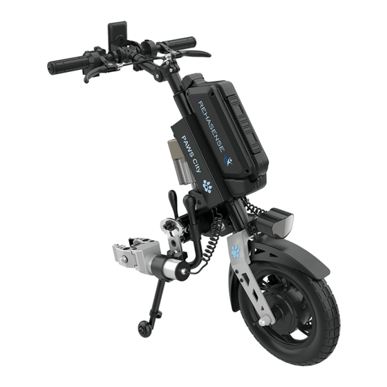
- Page 8 Battery Display Lock Battery Handlebars Driving Light Lift Mechanism Drive Clamp Wheel Mechanism Disc Support Brake Legs Figure 1. Main Elements for the Device (example shown is manual clamp and lift configuration) Cleaning. Attention! Water penetration can destroy the electrical system, motor, and the battery pack. The Manufacturer shall not be liable for damage caused by water inside the device.
- Page 9 Storing and Commissioning Store in a dry room, out of direct sunlight, Remove the battery pack after fully charging and wrap it in film, Also protect the device with film to keep moisture out, Ensure that unauthorized persons (especially children) do not have unsupervised access to this room. ...
- Page 10 Part name Control type Control frequency Device Battery and Charger Ensure contact points are clean on the battery and its housing by Whenever recharging the battery. wiping with a dry cloth. Also check that the plug and battery socket for charging are clear of any dirt or metal particles.
- Page 11 Turning wheels The area between the fork and the front wheel should be kept clean, The maintenance ought because dirt accumulating there can cause faster wear of caster to be made once a month bearings. To do so, one should disassemble the front caster by or more often depending disassembling it from the fork, to remove all dirt, and then preserve on usual surface type &...
- Page 12 Error code Function (Grouping) Error description Solution Error 03 No throttle response Brakes are locked on - Release the brake to re-open power power circuit interrupted circuit. Error 05 Throttle broken 1. Check the throttle cable 2. Change throttle 3. Contact dealer Error 04 Cannot change gear Throttle partly engaged.
-
Page 13: Warranty
Reading the User Manual Correct fitting and setup by a trained Product Specialist Training for correct use by a suitably qualified product specialist Timely maintenance being completed within required service schedule intervals Warranty PAWS comes with a 24-month warranty for all parts (except for the battery) against manufacturer defect or faulty materials. - Page 14 Check the Compatibility and Connection Table (CCT) to confirm that your wheelchair can be used safely with PAWS and reference the CCT for critical dimensions and clamp pressure CCT shows range of frame tube diameter, wall thickness and material that may be fitted with the ...
- Page 15 The device and chair coupling must be performed by an authorised PAWS distributor. The warranty is limited to replacement due to defects in parts or workmanship. REHASENSE shall not be required to replace any units that malfunction or are damaged due to abuse, accidents, alteration, misuse, neglect, maintenance by someone other than REHASENSE or sales partner, or failure to operate the instrument in accordance with this user manual.
- Page 16 All mechanical defects and damages caused by improper use or usage not intended by manufacturer are not covered by warranty. Unauthorized changes and modifications of the device will cause loss of warranty. Range of responsibility - This Warranty does not cover. transport cost, ...
- Page 17 Type - The Type describes key elements of the device. The codes for each of the ten places in the Type is described below: - Place 1 - The Manufacturer – “R” for Rehasense Place 2 – The Family – “P” for PAWS Place 3 –...
- Page 18 RPC16AAS00 PAWS / CRUISER 16" / AUTOMATIC CLAMP & LIFT / NORMAL Cruiser Auto Auto 16" HANDLES RPC16AAT00 PAWS / CRUISER 16" / AUTOMATIC CLAMP & LIFT / TETRA Cruiser Auto Auto 16" HANDLES RPT20MMS00 PAWS / TOURER 20" / MANUAL CLAMP & LIFT Fat tyre 20"x4"/ Tourer Manual Manual...
- Page 19 These limits will be programmed at the time of manufacture and will be controlled in steps to reach the maximum permitted speed as determined by the traffic authorities. If a lower limit is required than the local regulations permit, then this can be programmed by the authorised Rehasense PAWS representative in the delivery location. (mm) 12”...
-
Page 20: Corrosion Protection
Dia. Tread Pattern Description Dia. Tread Description 16” Brand: CST 20” Brand: CST Size: 16X3.0 Size: 20X4.0 ETRTO: 75-305 ETRTO: 100-406 Pattern: C-1488 Pattern: C-1752 Air Pressure: 35-45 P.S.I / Air Pressure: 30 P.S.I / 2.4-3.1 Bar 2.0 Bar Car Valve Car Valve 20”... - Page 21 Attention! These configurations are set during manufacture and can only be changed by the Manufacturer or authorized dealers with approved components. Configuration The needs of the User determine the set-up of the device and controls. The set-up offering the most assistance is for Users with restricted neuro-muscular abilities.
- Page 22 Speed Mode Button - Down Selects higher speed modes Brake Handle Lever Control braking during driving e-Driving Brake Control braking during driving Braking Parking Brake Catch Controls stationary braking Parking Brake Controls stationary braking Figure 7. PAWS Device Controls Figure 8. Standard Controls Figure 9.
- Page 23 Figure 10. Auto clamp/ lift switch Connecting and Lifting 1. Set the auto clamp/lift switch to the middle position. 2. Press the red button to activate the auto clamp function. You have 20 seconds to operate. 3. In the case of AM types, points 1 and 2 apply. The lifting will be done manually. 4.
- Page 24 Display Connection between Controller and Residual Battery Screen Cruise Reverse Forward Power Instant Speed Consumption Efficiency Traction Mode Walking Mode Driving Mode Driving Status Total Travel Distance Instant Power Single Travel Time E- Parking Walking Mode Motor Temperature Controller Temperature Controller Voltage Controler Current Figure 11.
- Page 25 13.1 Naming of Parts. Description This section shows and names all major assemblies and key functional parts in the device for Manual and Auto Docking Assemblies. Clamp Height Quick Release Lever Adjustment Plate Quick Release Nut Clamp Lever Locking Bolt A (Angle) Clamp Jaws Clamp Receiver...
- Page 26 Procedure Setting up the device on its legs with Clamps in position. Remove all parts from the packing box and check against Figure 14, below. Handy Tip: If possible, keep the carton and packing in reserve against future needs for transporting. Charger Battery Width Adjusting Rod...
- Page 27 Press on the Lift Lock Lever on the handlebar and pull back the Support Legs to the Park position, to allow the device to stand freely. Attention! “Park” is the position required for docking and un-docking during the clamping steps. ...
- Page 28 When docked, the Clamp Jaws should be in the middle section of the front chair tubes or where there is a section of straight tube slightly greater than the clamping area of the Clamp Jaws. Attention! Avoid pinching on pipe sections that are not straight Figure 19.
- Page 29 Figure 21. Adjusting the Tension Nut for the Width Adjustment Lever (Note the Width Setting Ring on the lower rod) Handy Tip: adjust the Width Setting Ring Bolt D on the lower rod of the Clamp Receiver – fix this in place to mark the width and make it easy to reposition if the Clamping structure needs to be removed for transport.
- Page 30 Figure 23. Changing the Lateral Angle and the Depth of the Clamp Jaws. Setting the Frontal Angle of the Clamp Jaws to the front tubes. Rotate the Clamp Jaws so that they are parallel to the tubes. Figure 24. Changing the Frontal angle of the Clamp Jaws. Setting the depth of the Clamp Jaws to the device.
- Page 31 This configuration is available in 12”, 14”, 16” and 20” versions. Please check Figure 4. Model Decoder -Types and Descriptions. Please review Figure 13 for the naming of parts. Procedure. Remove all parts from the packing box and check against the list in Section 9 (above). Handy Tip: If possible, keep the carton and packing in reserve against future needs for transporting.
- Page 32 Figure 28. Rotating the Support Legs to the Park Position Press on the Lift Lock Lever and pull back the Support Legs to the Park position, to allow the device to stand freely. Attention! “Park” is the position required for docking and un-docking during the clamping steps. Figure 29.
- Page 33 Attention! Avoid clamping to uneven tube sections. Figure 30. Different positions for Height Adjustment. Attention. The recommended Torque setting of Bolt C is 35 Nm (Newton Meters). Setting the Clamp Jaws. These need to be set for width, angle, and depth so that the clamping forces are equal on both sides. All adjusting bolts and QR Levers need to be loosened or released before starting this process.
- Page 34 Figure 32. Roll the Chair to the Device Handy Tip: Adjust the Width Setting Ring Bolt D on the lower rod of the Clamp Receiver – fix this in place to mark the width and make it easy to reposition if the Clamp Mechanism needs to be removed for transport. All other adjustment settings will be retained.
- Page 35 Setting the depth of the Clamp Jaws to the device. Adjust the Clamp depth (determines the distance from the device to the chair) to ensure space between the Users knees and the device. Figure 35. Showing the Depth adjustment of the Clamp mechanism in relation to the device. Attention! The Clamp mechanism and the Clamp Receiver must maintain full contact –...
- Page 36 Charger Battery Width Adjusting Rod Width Adjusting Auto Clamp PAWS Assembly Assembly Left Auto Clamp Tools Assembly Right Figure 36. Packaging of the automatic device The assembly of the automatic clamp is presented in section 13.3 Operating Description This section describes the processes for starting up, operating, and shutting down the device with the chair. Battery Ensure the battery is fully charged before a period of extended use.
- Page 37 Figure 37. Manual Lift Lever and Auto Clamp/Lift Button Attention! If needed, the Clamp and Lift sequence can be paused after clamping by returning the switch to the neutral position. Attention! After device is turned on, any actuation of throttle handle is a command to drive, so ...
- Page 38 If a lower limit is required than the local regulations permit, then this can be programmed by the authorised Rehasense PAWS representative in the delivery location. Rotate the throttle to the desired speed. Hold at this point to maintain the desired speed.
- Page 39 Immobilizer/display lock - It is recommended to set up an immobilizer. This consists of a 3-digit code that you can select individually. This serves to prevent unauthorized use by third parties. Proceed as follows: Power button/ Confirm entry Down Step 1: Switch on your PAWS. Step 2: Press both buttons (- &...
- Page 40 Step 10: Select your number by pressing (- OR +). Confirm the entry with the Power button. Step 11: Press the (-) button 1x and confirm your entry with the Power button. Repeat steps 10 and 11 in order to pick the second and third number.
- Page 41 Step 16: Press the Power button for approx. 2 seconds. PAWS will be switched off. Step 17: Press the Power button for approx. 2 seconds. PAWS will start (see image). Now you will be asked to enter your password. Step 18: Enter your numbers by pressing the buttons (+ or -) and confirm the entry with the Power button.
-
Page 42: Traction Control
Cruise Control Driving speed can be set without the need to hold the Throttle in position. This is done by using the Cruise function. Hold the throttle at a steady speed while pressing the Cruise button for 2 seconds. ... - Page 43 When re-starting from being parked on a slope, simultaneously release the brakes, and gently apply the throttle to hold the device on the slope. Wherever possible, avoid parking on inclines and gradients. Do not use the chair brakes to slow down, only for parking. ...
- Page 44 The Aero Battery (Lithium Ion 48V 5.6Ah, 300 Wh, 2.05 kg) has a lower power level so that it can be carried on passenger planes according to IATA. Note: Please ask your approved Rehasense PAWS dealer about the full range of accessories available for PAWS. Version 01/22...
-
Page 45: Appendix 1: Battery And Charger
Appendices 16.1 Appendix 1: Battery and Charger Attention! Read carefully before charging and operating the first time. Before starting up the power add-on and before charging the battery pack, read and observe the general information and instructions and the safety instructions and precautions in UM. Failure to comply with the safety precautions and instructions may damage the product or result in electric shock, fire, and/or serious injuries. - Page 46 4 LED light up-76% to 100% residual capacity available Within each range, the brighter the LED, the more residual capacity remains. Under Charging mode 1 LED light flash- have been charged up to 0% - 25% 2 LED light flash-have been charged up to 26% - 50% 3 LED light flash-have been charged up to51% - 75% 4 LED light flash-have been charged up to76% - 100% Note: The residual capacity of battery pack is indicated at two places: the screen display on the handlebar and LED...
- Page 47 Switch off: press the button for a few second till the light is off. Note: if under one of the below situations, the battery will enter sleeping mode after 30 minutes. Press shortly to inactivate it again. Output current less than 1A. ...
- Page 48 Performance and safety are only possible if the Battery is charged with original charger, in compliance with correct operating procedure, at a voltage and temperature within the specified ranges. The battery should be stored at room temperature with 40% to 60% of capacity. It must be charged ...
- Page 49 Power High Beam: 40 W Low Beam:9 W Working Voltage – 12V to 55V Visible Distance :1200M Waterproof Level: IPX4 Detailed Instructions. In low light mode, the middle three main LED’s light up When in the high beam mode, the middle three LED’s and the left and right three LED’s will all be ...
- Page 50 Instructions. Connect one end of the air tube to the inflator, connect another end to the tyre valve. (For the French valve, please install the valve converter at first ) Long press the POWER Button to turn on the power. The LCD will display the current pressure. Pressing the UNIT button can switch the units (PSI\BAR\KPA/kg.
-
Page 51: About Charging
3. If the power is turned on, the power bank will be turned off automatically. 4. Support Android and iOS equipment. About Charging For the first time to use or a long time no use, please charge Inflator first. The charging indicator will turn red during the charging and turn green when the battery is fully charged. - Page 52 Contact details of the distributor, manufacturer. In case of any technical questions contact your local distributor or directly with The Manufacturer. Distributor: Rehasense® Sp. z o.o. Sulejowska 45 G 97-300 Piotrków Trybunalski Poland www.rehasense.com info@rehasense.com Version 01/22 Page 52 of 52...
Need help?
Do you have a question about the City Series and is the answer not in the manual?
Questions and answers