
Related Manuals for Rehasense City Series


Summary of Contents for Rehasense City Series
- Page 1 Power Assisted Wheelchair Systems PAWS User manual (EN) City, Cruiser and Tourer Series City 12”/14” Cruiser 16” Tourer 20” more than mobility Version 10/21 Page 1 of 49 PAWS UM EN...
- Page 2 INDEX Section Topic Page General Information, Intended Use and Quality Standards Safety Warnings and Recommendations General Description Cleaning Transport and Storage Recycling and Disposal Maintenance and Service Reuse Warranty and Liability Scope of Delivery and Identification Product Specification Configurations, Controls and Display Device Assembly 13.1 Naming of Parts 13.2 Assembly –...
-
Page 3: Quality Standards
General Information, Intended Use and Quality Standards Thank you for choosing a PAWS Power Add-On Scooter for manual wheelchairs. This User Manual contains detailed information on the device and important guidelines to ensure correct and safe usage. Please read this manual carefully. It is especially important that you understand and follow the safety requirements. In this User Manual, we use the following terminology: - Device –... - Page 4 ALWAYS reduce speed when driving under these conditions. REHASENSE recognizes and encourages each individual to try what works best for them in overcoming the architectural obstacles they may encounter. However, all warnings and cautions given in this manual MUST be followed. Techniques in this manual are a starting point for the new user and assistant with “safety”...
- Page 5 The Device is not recommended for use on sand, mud or in extreme weather conditions unless • indicated in the model’s approved use environments. The temperature range for use is between -25 degrees Celsius and 50 degrees Celsius. • The Device should not be exposed to strong electrical fields, excessive heat, or moisture. •...
- Page 6 If defects or errors are detected, bring the device to a gradual stop (if in use) and immediately contact • your Distributor. Do not remove any parts or make any constructive changes to the Device, as this may influence the •...
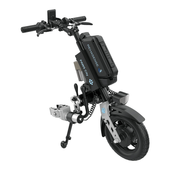
- Page 7 General Description of the Device The Device is an electrically powered towing mechanism that attaches to a manual wheelchair, converting it into a power-assisted wheelchair. The range and performance of the Device greatly increases the wheelchair Users’ daily travel range under all but the most extreme conditions.
- Page 8 Battery Display Lock Battery Handlebars Driving Light Lift Mechanism Drive Clamp Wheel Mechanism Disc Support Brake Legs Figure 1. Main Elements of the Device (example shown is manual clamp and lift configuration) Cleaning Attention! Water penetration can destroy the electrical system, motor, and battery pack. The Manufacturer shall not be liable for damage caused by water inside the Device.
- Page 9 Storing and Commissioning Store in a dry room, out of direct sunlight. • Remove the Battery Pack after fully charging and wrap it in film. • Wrap the Device in film to keep moisture out. • Ensure that unauthorized persons (especially children) do not have unsupervised access to the storage •...
-
Page 10: Control Frequency
Part name Control type Control frequency Device Battery and Charger Ensure the battery contact points and housing are clean by wiping with When recharging the a dry cloth. Further, check that the plug and battery socket for battery charging are clear of any dirt or metal particles. Brake Levers Brake cables may stretch over time. - Page 11 Turning wheels The area between the fork and front wheel should be kept clean to Once a month depending avoid excessive wear on the caster bearings. Disassemble the front on usage surface & caster by separating it from the fork to remove all dirt, then apply conditions.
- Page 12 Error alarm Error description Solution Error 01 Normal condition None Error 03 Braking Release the brake Error 04 Throttle does not go to "0" Release the throttle 1. Check the throttle cable Error 05 Throttle broken 2. Change throttle 3. Contact Distributor 1.
-
Page 13: Important Safety Instructions
Reuse PAWS may be used by another person if required, but it must undergo technical inspection by an authorized specialist/Distributor before transferring to a new User, in accordance with the "MAINTENANCE" chapter. The device must be set up for the new User’s abilities and needs. All functional areas must be checked – especially the handlebar controls. In addition to processes described in the “CLEANING”... - Page 14 Clamping Force 2000 N Irregular or composite profiles Asymmetric or Composite Fibres - interface adaptors needed* * Contact the authorised distributor for PAWS to find out which composite frames or irregular profiles can be fitted with adaptors. How to Extend Wheelchair Lifespan When Using PAWS Power Drive Systems. Ensure your wheelchair is compatible for connection with PAWS: •...
- Page 15 Device and Wheelchair coupling must be performed by an authorised PAWS distributor. The Warranty is limited to replacement due to defects in parts or workmanship. REHASENSE shall not replace any units that malfunction or are damaged due to abuse, accidents, alteration, misuse, neglect, maintenance by someone other than REHASENSE or an authorised sales partner, or failure to operate the instrument in accordance with the instructions in this User Manual.
- Page 16 The Warranty does not include: Devices whose serial numbers have been tampered with or removed. • Worn parts such as tyres, grips, handles, levers, and spokes. • Defects caused by normal wear, incorrect handling including non-compliance with the instructions in this User •...
- Page 17 Manufacturer Figure 2. Label Type - Type describes key elements of the Device. The codes for each of the ten places in Type are described below: Place 1 – The Manufacturer: “R” for REHASENSE Version 10/21 Page 17 of 49...
- Page 18 Place 2 – The Family: “P” for PAWS Place 3 – the Style: “I” for City; “C” for Cruiser; “T” for Tourer Places 4 and 5 – Wheel Diameter: 12”; 14”; 16”; 20” Places 6 and 7 – Docking: “MM” Manual Lift/Clamp; “AM” Auto Lift/Manual Clamp; “AA” Auto Lift/Clamp Place 8 –...
- Page 19 Max. weight of person: (kg) Max. overall weight:(kg) 140.8 141.3 143.8 147.5 148.8 Total weight less 17.5 20.5 24.2 25.5 battery:(kg) Battery Weight: (kg) 20.8 21.3 23.8 27.5 28.8 Total weight: (kg) Motor Power: (W) 1100 1100 1100 Motor max input power (W) Motor MAX Torque(N.M) Motor Voltage: (V) 11.6...
- Page 20 Speed modes 1-2 are for each product. • Speed limits are determined according to local traffic regulations. These limits will be programmed at the time of • manufacture and are tiered from 1 (slowest, akin to a gentle walking pace) to 5 (fastest); 5 being the maximum legally allowed by the traffic authorities.
- Page 21 Description The Device is configured at the time of ordering and may involve a therapist with the Distributor and User discussing the options that best suit the User’s situation. Thus, the set-up of controls of the Device will be matched to the driving, braking, and docking options chosen by the User at the time of ordering.
- Page 22 Head Light Switch Selects 3 headlight settings Safety Horn Button Audible warning button Auto Clamp/Lift Switch Clamp/Unclamp & Lift/Lower Docking Manual Lift Control Lever Control 3 Lift Positions Screen Driver Display Direction Switch Forward or Reverse Throttle Handle Controls acceleration Tetra Throttle Handle Controls acceleration Drive...
- Page 23 Display Connection between Controller and Residual Battery Screen Cruise Reverse Forward Power Instant Speed Consumption Efficiency Traction Mode Walking Mode Driving Mode Total Travel Driving Status Distance Instant Power Single Travel Time E- Parking Figure 10. Display Functions Walking Mode Motor Temperature Controller Temperature...
- Page 24 Device Assembly Introduction This section describes: - Assembly according to the clamping and lifting configuration chosen • General operation, with exceptions where configurations vary • 13.1 Naming of Parts Description This section shows and names all major assemblies and key functional parts of the Device for Manual and Auto Docking Assemblies.
- Page 25 13.2 Assembly – Manual Clamp and Lift Introduction This configuration is available in 12”, 14”, 16” and 20” versions. Please check the model number in the model decoder in Section 9. The Manual clamps are assembled and adjusted to fit the chair. The Lift is controlled by a lever on the Handlebar and has three positions –...
- Page 26 Stand and support the Device on its wheel. Rotate the Support Legs outwards to support the Device in • the standing position. Ensure the locating bolts at the top of the Supporting Legs are clearly in the key- way slot. Figure 15.
- Page 27 Fitting to the chair. Introduction Connecting the chair to the Device is important – only clamp the Device to the front tubes of the chair and not to any removable or swing-away parts. It is important to clamp the Device evenly to the chair. Please take time to ensure the best fit.
- Page 28 Attention! The tension on this lever can be adjusted using the nut on the other side of the lever. See Figure 11 above. Figure 19. Reversing the Clamp Mechanism Receiver to inward orientation Figure 20. Adjusting the Tension Nut for the Width Adjustment Lever (Note the Width Setting Ring on the lower rod) Handy Tip: Adjust the Width Setting Ring Bolt D on the lower rod of the Clamp Receiver –...
- Page 29 Figure 21. Opening and adjusting the width of the Clamp Jaws. Adjust the lateral angle of the Clamp Jaws to the front tubes. Adjust the Clamp Jaw angle to the • Wheelchair tube by rotating at Bolt A. The Clamp Jaws should grip the Wheelchair tube evenly when they are closed.
- Page 30 Attention! The Clamp mechanism and Clamp Receiver must maintain full contact – do not extend the depth beyond what is possible with full contact of the Receiver and Clamp mechanism. Do this for both sides ensuring that the calibration marks for angle, rotation and depth are approximately the same. Close the Clamp Jaws and then adjust the Clamp Jaw Tensioning Nut (see Figure 21) to 8 Nm Torque •...
- Page 31 Figure 26. Assembling the Clamp Assembly to the Width Adjustment Assembly Stand and support the Device on its wheel. Rotate the Support Legs outwards allowing them to support the • Device in a standing position. Ensure the locating bolts at the top of the Supporting Legs are clearly in the key- way slots.
- Page 32 Fitting to the Wheelchair Introduction Attention! Do not move the Device while it is standing only on its support legs – this may cause the legs to rotate if not properly engaged in the rotation lock, causing the Device to fall. Connecting the Wheelchair to the Device is important –...
- Page 33 Adjust the centres of the Clamp Jaws to align with the centres of the Wheelchair front tubes by moving • the Clamp Assembly in or out of the Width Adjustment Assembly. Adjust the Jaw opening, using the spanner provided, to easily receive the front tube of the Wheelchair. •...
- Page 34 Figure 32. Changing the Lateral Angle and Depth of the Clamp Jaws. Setting the Frontal Angle of the Clamp Jaws to the front tubes. Rotate the Clamp Jaws parallel to the • tubes. Figure 33. Changing the Frontal angle of the Clamp Jaws Setting the depth of the Clamp Jaws to the device.
- Page 35 Then press the Device Power Button for three seconds to power up the Device. • Close the Jaws by pressing the Auto Lift Clamp Switch to the right side – indicating jaws closed – until • the jaws have closed. Then immediately return to the middle or neutral position on the switch so as not to go to the lifting position.
- Page 36 Figure 35. Manual Lift Lever and Auto Clamp/Lift Button Attention! The Clamp and Lift sequence can be paused after clamping by returning the switch • to the neutral position. Attention! When the Device is turned on, any actuation of the throttle handle is a command to •...
- Page 37 Parking Position Touring Position City Position Figure 37. Indicator for Rake Positions for Manual Clamp/Lift Devices Leg supports Attention - Never rotate the Supporting Legs forward during use! These should remain in the ready position to support the power add-on when not connected to the Wheelchair. Folding them forward may interfere with the turning ability of the steering column.
-
Page 38: Traction Control
If a lower limit is required (lower than local regulations permit), this can be programmed by the authorised REHASENSE PAWS representative in the delivery location. Rotate the throttle to the desired speed. Hold at this point to maintain the desired speed. - Page 39 Driving Brakes For Standard control handlebars, driving brakes are applied by pulling the Brake Levers on either side • of the Handlebars. Use a single Brake lever for lower speed braking and both levers for medium to higher speed braking. For Tetra Handlebar control, driving brakes are activated by rotating the left side Tetra Handle.
- Page 40 Ensure the headlight is on whenever driving – car drivers may not see a wheelchair driver, and if they • do, they will not expect the Wheelchair to be traveling faster than walking speed. Inclines, climbing ability and obstacles. The maximum gradient for climbing is 10%. •...
- Page 41 Accessories Figure 40. Accessories (L to R) Tyre Inflator; Basket; Phone Holder; Aero Battery Smart Tyre Inflator A portable USB tyre inflator is used for checking pressure and inflating tyres. See “Appendix 3: Smart Tyre Inflator” for detailed operation. Basket A basket may be attached to the 20”...
-
Page 42: Appendix 1: Battery And Charger
Appendices 16.1 Appendix 1: Battery and Charger Attention! Read carefully before charging and operating the first time. Before starting up the power add-on and before charging the battery pack, read and observe the general information and instructions and the safety instructions and precautions in this User Manual. Failure to comply with the safety precautions and instructions may result in electric shock, fire, and/or serious injuries to the User, and damage to the product. - Page 43 Within each range, the brighter the LED, the more residual capacity remains. Charging mode • 1 LED light flashing: -charged up to 0% - 25% 2 LED light flashing: -charged up to 26% - 50% 3 LED light flashing: -charged up to51% - 75% 4 LED light flashing: -charged up to76% - 100% Note: The residual capacity of the Battery Pack is indicated in two places: the screen display on the handlebar and LED lights on the Battery Pack.
- Page 44 Note: In the below situations, the Battery will enter Sleep Mode after 30 minutes. Press the button briefly to reactivate. Output current less than 1A • Disconnected with controller signal • Charging current less than 100mA • Charging the Battery Pack The Battery can be charged while in the device or separately.
-
Page 45: Specifications
The Battery should be stored at room temperature at 40% to 60% capacity, and must be charged • monthly while in storage. Battery performance cannot be guaranteed if left in storage for more than one year. • Attention! Light operation during battery charging. If the Output Light is not working: Check whether there is alternating current •... -
Page 46: Detailed Instructions
Working Voltage: 12V to 55V • Visible Distance: 1200M Waterproof Level: IPX4 Detailed Instructions In Low Light mode, the middle three LEDs light up • When in High Beam mode, the middle three LEDs and the left and right three LEDs will all be on, •... - Page 47 Instructions. Connect one end of the air tube to the Inflator, and the other end to the tyre valve. (For the French valve, please install the valve converter first) Long press the POWER Button to turn on the power. The LCD will display the current pressure. Pressing the UNIT button can switch the units (PSI\BAR\KPA/kg.
-
Page 48: About Charging
About Charging Charge the Inflator before first use or after an extended period without use. The Charging Indicator will turn red during charging and green when the Battery is fully charged. Safety The Inflator becomes hot after working more than 1 min. Do not touch the hot area of the air tube. Please check the Inflator before inflating. - Page 49 Contact details of the distributor. In case of technical questions, contact your local Distributor. Distributor: Aidacare Healthcare Equipment 3A/1 Moorebank Ave Moorebank, NSW 2170 T – 1300 216 898 E – online@aidacare.com.au Version 10/21 Page 49 of 49 PAWS UM EN...
Need help?
Do you have a question about the City Series and is the answer not in the manual?
Questions and answers