
Related Manuals for Rehasense City Series


Summary of Contents for Rehasense City Series
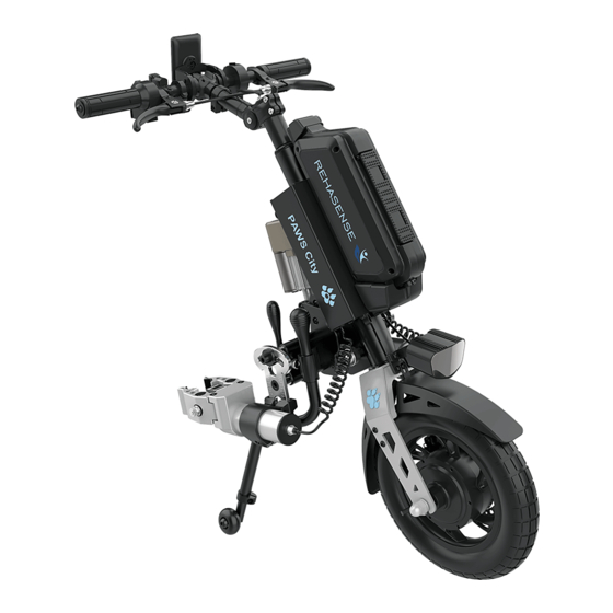
- Page 1 Power Assisted Wheelchair Systems PAWS User’s manual (EN) City, Cruiser and Tourer Series City 12”/14” Cruiser 16” Tourer 20” more than mobility Version 01/21 Page 1 of 44 PAWS UM EN...
- Page 2 INDEX Section Topic Page General Information, Intended Use and Quality Standards Safety Warnings and Recommendations General description Cleaning and Storage Recycling and Disposal Maintenance and Service Warranty and Liability Scope of Delivery and Identification Specification Configurations, Controls and Display Device Assembly 11.1.
- Page 3 General Information, Intended Use and Quality Standards. Thank you for choosing a PAWS Power Add-On Device. This user manual contains a description of the device and important guidelines to ensure a correct and safe usage. Please read this manual carefully. It is especially important to read the safety requirements and to follow these. In this User Manual, we use the following terminology: - Device –...
- Page 4 If there are any areas where the concepts are not clear, please contact your authorised The Manufacturer Dealer or The Manufacturer directly (info@rehasense.com) for further clarification. Consult – talk to a person qualified in supplying, fitting, and servicing the device.
- Page 5 When device is attached to the chair, it is regarded as a three-wheel vehicle. Reduce speed when turning, going across kerbs, cambers, and bumps to avoid tipping over. Always be mindful of your speed when driving on public roads or footpaths. Please observe and ...
- Page 6 company, shipping company) to find the best way to transport your device’s batteries. WARNING! The device and chair are not designed as a seating option for a user in moving vehicles (like e.g. buses, trains, metro, airplanes etc.). It is forbidden to seat on the device in moving vehicle. The device and chair should be safely stowed and secured for the time of transportation.
- Page 7 12”/14” Wheel (City): lowest weight, battery consumption, torque (35 Nm) and motor power. Most manoeuvrable. Suitable for indoors and tarmac road. Best at low to middle speed range. 16” Wheel (Cruiser): middle weight, battery consumption, torque (60 Nm) and motor power. Suitable for ...
- Page 8 Cleaning and Storage. Attention! Water penetration can destroy the drive and the battery pack. The Manufacturer shall not be liable for damage caused by water inside the device. Please Attention that water damage is not covered by our warranty Cleaning Do not clean the individual components of the device under running water or with a high-pressure cleaner, ...
- Page 9 Recycling and Disposal Support sustainability by adhering to local regulations for recycling and disposal of the device once its serviceable life is ended. The device is labelled in accordance with European Directive 2002/96/EC (WEEE Directive) with a “crossed-out rubbish bin” symbol, reminding you that it must be recycled, All materials may be recycled once the device has finished its serviceable life, ...
-
Page 10: Control Type
Part name Control type Control frequency Device Battery and Charger Ensure contact points are clean on the battery and its housing by Whenever recharging wiping with a dry cloth. Also check that the plug and battery socket the battery. for charging are clear of any dirt or metal particles. Brake Levers Brake cables may stretch over time. - Page 11 Turning wheels The area between the fork and the front wheel should be kept clean, The maintenance ought because dirt accumulating there can cause faster wear of caster to be made once a bearings. To do so, one should disassemble the front caster by month or more often disassembling it from the fork, to remove all dirt, and then preserve depending on usual...
- Page 12 Error alarm Error description Solution Error 01 Normal condition None Error 03 Braking Release the brake Error 04 Throttle does not go to "0" Release the throttle 1. Check the throttle cable 2. Change throttle Error 05 Throttle broken 3. Contact dealer 1.
- Page 13 Warranty and Liability Warranty - If any defects or damages occur, the User should immediately inform the supplier. Warranty for defects - The Manufacturer guarantees that the device is free of defects at the time of delivery. This warranty expires 24 months after the date of delivery of the device, During that period, all material, or parts defects (excluding the Battery), caused by manufacturing faults or usage ...
- Page 14 Scope of Delivery and Identification Scope of Delivery The Device is delivered partially disassembled and requires setting up and adjusting after unpacking. This should be done by an authorised dealer Please check the contents of the box before proceeding to Assembly. Each delivery includes these items: - Main frame, handlebar assembly and drive wheel - assembled ...
- Page 15 Type - The Type describes key elements of the device. The codes for each of the ten places in the Type is described below: - Place 1 - The Manufacturer – “R” for Rehasense Place 2 – The Family – “P” for PAWS Place 3 –...
- Page 16 Specifications Element City 12"/14" Wheel Cruiser 16" Wheel Tourer 20" Wheel Overall L*W*H: (mm) 800 x 490 x 810 820 x 490 x 860 1000 x 520 x 920 Packing L*W*H: (mm) 1070 x 600 x 290 1100 x 600 x 290 1260 x 705 x 290 Max.
- Page 17 (mm) 12” 16” 20” 1000 Device in Park Position Battery Table Dimensions Figure 5. Device and Battery Dimensions Dia. Tread Pattern Description Dia. Tread Description 12” Brand: CHAOYANG 20” Brand: CST Size:12 1/2 x 2 1/4 Size:20X2.125 ETRTO: 52-203 ETRTO: 57-406 Pattern:H-5 Pattern:C-1488 Air Pressure: 40 P.S.I...
- Page 18 Assistance is in 2 forms Power Assisted Docking – Clamping/Unclamping & Lifting/Lowering Driving and Braking – Tetra controls to support these actions The Tetra Handlebars for those with diminished trunk and upper extremity strength and fine motor control. The main difference is the gripping method for the hand controls for throttle (right hand) and brake (left hand).
- Page 19 Figure 7. PAWS Device Controls Figure 8. Standard Controls Figure 9. Tetra Controls Display The Display is mounted in the middle of the handlebars and may be rotated to the best position by loosening, adjusting, and retightening the clamp bolts on the Display Mounting Bracket. It displays crucial information about the device system, driving controls and running performance.
- Page 20 Connection between Residual Battery Controller and Cruise Screen Forward Reverse Instant Speed Power Comsumption Traction Mode Efficiency Diving Mode Walking Mode Total Travelling Driving Status Distance Instant Power Single Travelling Time Figure 10. Display Functions Device Assembly Introduction This section will describe: - Firstly, the assembly according to the clamping and lifting configuration chosen ...
- Page 21 Clamp QR Lever Height Adjustment Plate QR Nut Clamp Jaws Locking Bolt A (Angle) Clamp Mechanism Width Adjustment Rod Receiver Width Setting Ring Locking Bolt B (Depth and Angle) Figure 12. Auto Clamp and Width Assemblies 11.2 Assembly – Manual Clamp and Lift. Introduction This configuration is available in 12”, 14”, 16”...
- Page 22 Figure 14. Assembling the Clamp Assembly to the Width Adjustment Assembly Attention! there is a “left” and a “right” clamp mechanism – each Clamp Lever must be on the outside of the device. Stand and support the device on its wheel. Rotate the Support Legs outwards - allow them to support the device ...
- Page 23 bolts in the Steering column to prevent the handlebars from unwanted movement. Attention! the Torque setting is 10 Nm (Newton Metres). Figure 17. Fixing the Handlebars in the Operating Position. Fitting to the chair. Introduction Matching the chair to the device is important – only clamp the device to the front tubes of the chair and not to any removeable or swing away parts.
- Page 24 sides. Adjust the width of the Clamp Jaws to the chair frame front tubes by pulling down the QR Levers to allow the Clamp Receiver mechanism to slide in and out of its housing. See Fig 11 above. Once the centre of the Clamping Jaws are in line with the mid-line of the chair tubes, close the QR Levers. ...
- Page 25 Figure 21. Changing the Lateral Angle and the Depth of the Clamp Jaws. Setting the Frontal Angle of the Clamp Jaws to the front tubes. Rotate the Clamp Jaws so that they are parallel to the tubes. Figure 22. Changing the Frontal angle of the Clamp Jaws. Setting the depth of the Clamp Jaws to the device.
- Page 26 11.3 Assembly – Auto Clamp and Lift Description. The electric Auto clamps are attached and adjusted to fit the chair. The Lift is controlled electronically on the Handlebar and has 3 positions – Parking, Short and Long Wheelbase positions. This configuration is available in 12”, 14”, 16” and 20” versions. Please check the model number in the model decoder in Section 9.
- Page 27 Figure 26. Rotating the Support Legs to the Park Position Press on the Lift Lock Lever and pull back the Support Legs to the Park position, to allow the device to stand freely. Attention! “Park” is the position required for docking and un-docking during the clamping steps. Figure 27.
- Page 28 Procedure Setting the height of the device in relation to the chair. The height relationship can be changed in 30 mm steps by moving the Clamp Mechanism Receiver in relation to the Width Adjusting mechanism. When docked, the Clamp Jaws should be in the middle section of the front chair tubes or where there is a section of ...
- Page 29 Figure 30. Roll the Chair to the Device Handy Tip: adjust the Setting Ring on the lower rod of the Clamp Receiver – fix this in place to mark the width and make it easy to reposition if the Clamping structure needs to be removed for transport. All other adjustment settings will be retained.
- Page 30 Attention! the Clamp mechanism and the Clamp Receiver must maintain full contact – do not extend the depth beyond what is possible with full contact of the Receiver and the Clamp mechanism. Do this for both sides ensuring that the calibration marks for angle, rotation and depth are approximately the same To close the Clamp Jaws firmly the device must be powered up.
- Page 31 12 Operating Description This section describes the processes for starting up, operating, and shutting down the device with the chair. Battery Ensure the battery is fully charged before a period of extended use. The battery should be fully charged after each use – this will extend the battery life ...
- Page 32 Driving Positions for Manual Lift Devices Apart from Parking (Position 1 on the indicator), there are two other driving positions – City and Tour – and these are controlled during the Manual process. Touring (Position 2 on the indicator) is when the handlebars sit the lowest and the wheelbase is longest. This is ...
- Page 33 If Manual, press the Power Device to power up the system. Attention – Never turn off the device while driving! This will turn off the electric brake function. Select the Speed Mode to set the maximum driving speed ...
- Page 34 the throttle. Cruise Control Driving speed can be set without the need to hold the Throttle in position. This is done by using the Cruise function Hold the throttle at a steady speed while pressing the Cruise button for 2 seconds ...
- Page 35 When re-starting from being parked on a slope, simultaneously release the brakes, and apply the throttle gently to hold the device on the slope. Wherever possible, please avoid parking on inclines and gradients. Do not use the chair brakes to slow down, only for parking. ...
- Page 36 Figure 39. Accessories (L to R) Tyre Inflator; Basket: Phone Holder Smart Tyre Inflator A portable USB tyre inflator is used for checking tyre pressure and inflating tyres. See “Appendix 3: Smart Tyre Inflator” for detailed operations. Basket A basket may be attached to the 20” Tourer for carrying of personal items. It is positioned over the front wheel and provides extra traction when carrying additional weight.
-
Page 37: Appendix 1: Battery And Charger
14 Appendicies 14.1 Appendix 1: Battery and Charger Attention! Before starting up the power add-on and before charging the battery pack, read and observe the general information and instructions and the safety instructions and precautions in UM. Failure to comply with the safety precautions and instructions may damage the product or result in electric shock, fire, and/or serious injuries. - Page 38 2 LED light flash-have been charged up to 26% - 50% 3 LED light flash-have been charged up to51% - 75% 4 LED light flash-have been charged up to76% - 100% Note: The residual capacity of battery pack is indicated at two places: the screen display on the handlebar and LED lights on battery pack.
-
Page 39: Appendix 2: Headlight
The battery can be charged both when it is in the device or separately. Connecting the charging plug to battery pack Pull the rubber cover off the charger socket Insert the charging plug into the charger socket, there is a slot on the plug to make sure itis correctly matched ... -
Page 40: Appendix 3: Smart Tyre Inflator
Light Sensor Light Button Figure 43. Headlight Feature Light sensor There are three modes in the day: High Beam, Daylight, Low Beam. There are two modes in the night: High and Low Beams. The light automatically senses the ambient light intensity and change the light mode from Day to Night. Manually press to change modes. - Page 41 The Smart Tyre Inflator has a built-in rechargeable battery that drives a mini compressor for inflating tyres. Apart from automatically sensing the User set pressure limits, the device can provide power for external devices and has a light function. Instructions. 1.
- Page 42 install the valve converter at first ) 2. Long press the POWER Button to turn on the power. The LCD will display the current pressure. 3. Pressing the UNIT button can switch the units (PSI\BAR\KPA/kg. /cm2). (The recommended range of pressure can be found on the tire in general.) 4.
- Page 43 6. Do not leave unattended during the inflating process, to avoid accidents. 7. After long-time using, both the inflator and the air tube will become hot. Please take a break before using it again 8. Please try to avoid contact with dust or moisture and avoid dropping. 9.
- Page 44 In case of any technical questions contact your local distributor or directly with The Manufacturer. Distributor: Rehasense® Sp.z o.o. Sulejowska 45 G 97-300 Piotrków Trybunalski Poland www.rehasense.com info@rehasense.com Version 01/21 Page 44 of 44 PAWS UM EN...
Need help?
Do you have a question about the City Series and is the answer not in the manual?
Questions and answers