Table of Contents

Related Manuals for CDA GB RV 701 SS


Summary of Contents for CDA GB RV 701 SS
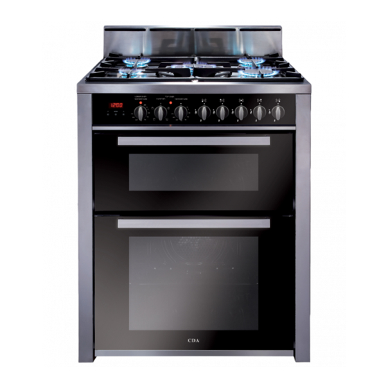
- Page 1 RV 701 SS - Dual Fuel Cooker Manual for Installation, Use and Maintenance Customer Care Department • The Group Ltd. • Harby Road • Langar • Nottinghamshire • NG13 9HY T : 01949 862 012 F : 01949 862 003 E : service@cda.eu W : www.cda.eu...
-
Page 2: Appliance Information
The CDA Group Ltd cannot be held responsible for injuries or losses caused by incorrect use or installation of this product. Please note that CDA reserve the right to invalidate the guarantee supplied with this product following incorrect installation or misuse of the appliance. -
Page 3: Features And Technical Data
Features and Technical Data Gas Burners 1. Auxiliary burner (A) 1,00 kW 2. Semi-Rapid burner (SR) 1,75 kW 3. Rapid burner (R) 3,00 kW 4. Triple Ring burner (TR) 3,50 kW Note: The electric ignition is incorporated in the knobs. The appliance has a safety valve system fitted, the flow of gas will be stopped if and when the flame should accidentally go out. -
Page 4: Control Panel
Control Panel Controls Description 1. Front right rapid burner control knob (3) 2. Rear right semi-rapid burner control knob (2) 3. Central triple-ring burner control knob (4) 4. Rear left semi-rapid burner control knob (2) 5. Front left auxiliary burner control knob (1) 6. -
Page 5: Clock And Timer With "Touch-Control" Keys
Clock and Timer with “Touch-Control” Keys (Bottom Main Oven only) Keys: – Touched simultaneously (for more than 2 seconds): • setting the clock; • setting the timer volume (by touching once, along with the “MODE” key); • to cancel automatic cooking at any time. MODE Function selection (touched for more than 2 seconds):... -
Page 6: Setting The Clock
“Touch-Control” Keys The “touch-control” keys shall be operated by the fingers (just by touching the key). When using touch controls it is best to use the ball of your finger rather than the tip. The keys are automatically deactivated: - 8 seconds after the last selection; the deactivation is indicated by an acoustic signal (“beep”). To reactivate just touch the “MODE”... -
Page 7: Automatic Cooking
Automatic Cooking Use automatic cooking to automatically turn the oven on, cook, and then turn the oven off. 1. Check the clock shows the correct time. 2. Select the function and temperature (function and temperature knobs). The oven will come on. 3. -
Page 8: How To Use The Hob Burners
How to Use the Hob Burners Hob Burners Each hob burner is controlled by a separate gas valve operated by a control knob (fig. 4) which has 3 positions marked on the control panel, these are: – Symbol : Tap closed (burner off) –... - Page 9 Choice of Burner The burner must be choosen according to the diameter of the pans and energy required. Saucepans with handles which are excessively heavy, in relationship to the weight of the pan, are safer as they are less likely to tip. Pans which are positioned centrally on burners are more stable than those which are offset.
-
Page 10: How To Use The Fan Oven (Bottom Main Oven)
How to Use the Fan Oven General Features Fan cooking is more economical and quicker than cooking in a conventional oven. The moving hot air surrounds the food and penetrates it more quickly than in a conventional oven. The oven is equipped with a circular element (2200 W) and a fan. Note: Upon first use, it is advisable to operate the oven at the maximum temperature (thermostat knob on position 250) for 60 minutes to eliminate any traces of grease from the electrical resistance. - Page 11 Switch and the Temperature Selector Rotate the knob clockwise to set the oven for one of the following functions: Off as per fig. 9 Only the oven fan is on. The fan operates without the heating element, this function can be used for defrosting.
-
Page 12: Cooking Advice
Cooking Advice Sterilization Sterilization of foods to be conserved, in full and hermetically sealed jars, is done in the following way: a - Set the selector knob to position 185 °C and preheat the oven. b - Fill the dripping pan with hot water. c - Set the jars onto the dripping pan making sure they do not touch each other and the door and set the knob to position 135 °C. - Page 13 How to Use the Convection Oven General Features The convection oven is equipped with 3 electrical heating elements: – 2 elements (upper and lower) for normal oven cooking – 1 grill element, on the top of the oven, for grilling which must be done with the oven door closed.
-
Page 14: Thermostat Knob
Thermostat Knob (fig. 11) This only sets the cooking temperature and does not switch the oven on. Rotate clockwise until the required temperature is reached (from 50° C to MAX). The light between the thermostat and the function selector will illuminate when the oven is switched on and turns off when the oven reaches the correct temperature. -
Page 15: Use Of The Grill
Lower Heating element In this position only the lower element is switched on. Heat is distributed by natural convection. The thermostat can be set between 50 and 150°C; higher temperatures are not available. Recommended for: This mode is particularly suitable to complete cooking of dishes that require higher temperature at the bottom. -
Page 16: Do's And Do Not's
Do’s and do not’s – Do always grill with the oven door closed. – Do read the user instructions carefully before using the cooker for first time. – Do allow the oven to heat for one and a half hours, before using for the first time, in order to expel any smell from the new oven insulation, without the introduction of food. -
Page 17: For Your Safety
For Your Safety – The product should only be used for its intended purpose which is for the cooking of domestic foodstuffs. – Under no circumstances should any external covers be removed for servicing or maintenance except by suitably qualified personnel. –... -
Page 18: Care And Maintenance
Care and Maintenance Important: As a safety measure, before you start cleaning the cooker be sure to disconnect it from the mains supply. - Do not use cleaning products with a chlorine or acidic base. - Do not use a steam cleaner because the moisture can get into the appliance thus make it unsafe. - Page 19 Stainless Steel, Aluminium, Painted Parts and Silk-screen Printed Surfaces Clean using an appropriate product. Always dry thoroughly. Stainless steel surfaces: can be cleaned with an appropriate stainless steel cleaner. IMPORTANT: these parts must be cleaned very carefully to avoid scratching and abrasion. You are advised to use a soft cloth and neutral soap.
- Page 20 Burners and Grids – These parts can be removed and cleaned with appropriate products. – After cleaning, the burners and their flame spreaders must be well dried and correctly replaced. – It is very important to check that the burner flame spreader and the cap have been correctly positioned. Failure to do so can cause serious problems.
- Page 21 Correct Position of Triple Ring Burner The triple ring burner must be correctly positioned (see fig. 14); the burner ribs must be fitted in their housing as shown by the arrow. The burner correctly positioned must not rotate (fig. 15). Then position the cap “A“...
- Page 22 Assembling and Dismantling of the Side Runner Frames – Assemble the wire racks to the oven walls using the 2 screws (Figs. 17a - 17b). – Slide the tray and rack into the runners (Figs. 18a - 18b). The rack must be fitted so that the safety catch, which stops it sliding out, faces the inside of the oven.
- Page 23 Inside of Oven The oven should always be cleaned after use when it has cooled down. The cavity should be cleaned using a mild detergent solution and warm water. Suitable proprietary chemical cleaners may be used after first consulting with the manufacturers recommendations and testing a small sample of the oven cavity.
-
Page 24: Removing The Oven Door
Top Oven Door Removing the Oven Door The oven door can easily be removed as follows: – Open the door to the full extent (fig. 20a). – Open the lever A completely on the left and right hinges (fig. 20b). –... - Page 25 Cleaning the Panes of Glass Do not use harsh abrasive cleaners or sharp metal scrapers to clean the oven door glass since they scratch the surface, which may result in shattering of the glass. Removing the Inner Pane of Glass The oven door has two panes.
- Page 26 Replacing the Inner Pane of Glass 1. Make sure the door is locked open (see figs. 21, 22, 23). 2. Replace the inner pane: – Check that the four rubber pads are in place (D in Fig. 25). – Check that you are holding the pane the correct way. You should be able to read the wording on it as it faces you.
- Page 27 Bottom Oven Door Note: The oven door should only be removed by an authorised service agent. Removal of the oven door by a non-authorised person will invalidate the guarantee. Removing the Inner Pane of Glass When removing and replacing the inner glass, the door should be held still by one person (fig.
- Page 28 Replacing the Inner Pane of Glass To replace the inner pane of the door operate as follows: – Check that the four rubber pads are in place (D in Fig. 31). – Check that you are holding the pane the correct way. You should be able to read the wording on it as it faces you.
-
Page 29: For The Installer
FOR THE INSTALLER Location This cooker has class “2/1” overheating protection so that it can be installed next to a cabinet. The appliance may be installed in a kitchen, Kitchen/diner or a bed sitting room, but not in a room or space containing a bath or a shower. - Page 30 If the cooker is installed adjacent to furniture which is higher than the gas hob cooktop, a gap of at least 200 mm must be left between the side of the cooker and the furniture. Curtains must not be fitted immediatly behind appliance or within 500 mm of the sides. It is essential that the cooker is positioned as stated in Fig.
- Page 31 Before installing the cooker level the appliance by screwing or unscrewing the four adjustable feet fitted below. WARNING! For safety reasons unscrew the feet (from screwed position) to the maximum extent of 5 mm (fig. 35). Backguard – Remove the two spacers “A” and the screw “B” from the rear of the cooktop. –...
- Page 32 Warning To move the cooker always ensure two people carry out this manoeuvre to prevent damage to the appliance (fig. 37). Warning Be carefull: do not lift the cooker by the door handle (fig. 38). Warning When moving cooker to its final position DO NOT DRAG (fig.
-
Page 33: Provision For Ventilation
Provision for Ventilation – The appliance should be installed into a room or space with an air supply in accordance with BS 5440-2: 2000. – For rooms with a volume of less than 5m required. – For rooms with a volume of between 5m required unless the room has a door which opens directly to the outside air in which case no permanent ventilation is required. -
Page 34: Gas Installation
Gas Installation Important Note This appliance is supplied for use on NATURAL GAS or LPG (check the gas regulation label attached on the appliance). – Appliances supplied for use on NATURAL GAS: they are adjusted for this gas only and cannot be used on any other gas (LPG) without modification. -
Page 35: Gas Connection
Gas Connection The installation of the gas appliance to Natural Gas or LP Gas must be carried out by a suitably qualified and registered installer. Installers shall take due account of the provisions of the relevant British Standards Code of Practice, the Gas Safety Regulations and the Building Standards (Scotland)(Consolidation) Regulations issued by the Scottish Development Department. - Page 36 Gas Connection Cat: II 2H3+ The gas supply must be connected to the gas inlet which is located at the rear of the appliance (see figure 41). If the connection pipe cross the cooker, it must be positioned under the cooker rear protection. To screw the connecting tube operate with two spanners (fig.
-
Page 37: Conversion To Natural Gas Or To Lpg
Conversion to Natural Gas or to LPG Injectors Replacement of Top Burners Every cooker is provided with a set of injectors for the various types of gas. Injectors not supplied can be obtained from the After-Sales Service. Select the injectors to be replaced according to the table at page 38. The nozzle diameters, expressed in hundredths of a millimetre, are marked on the body of each injector. -
Page 38: Lubrication Of The Gas Taps
Table for the Choice of the Injectors Burners Nominal Power Auxiliary (A) Semi-Rapid (SR) Rapid (R) Triple Ring (TR) Increase of Air Necessary for Gas Combustion (2 m Burners Auxiliary (A) Semi-Rapid (SR) Rapid (R) Triple Ring (TR) Lubrication of the Gas Taps The operations must be executed by a qualified technician. -
Page 39: Electrical Installation
Electrical Installation WARNING! Electricity can be extremely dangerous. This appliance must be earthed. The appliance must be connected to the electrical network verifying above all that the voltage corresponds to the value indicated on the specifications plate and that the cables section of the electrical plant can bear the load which is also indicated on the plate. - Page 40 Connection to Fixed Wiring A double pole switch must be provided no further than 2 metres from the appliance to the electrical supply. The appliance should be connected to a DOUBLE POLE SWITCHED FUSED SPUR OUTLET, similar to that shown in Fig. 47. DOUBLE POLE SWITCHED FUSED SPUR OUTLET FUSE...
-
Page 41: Appliance Servicing
Appliance Servicing CDA provide a quality and effective after-sales service to cover all your servicing needs. Please attach your receipt to this page for safekeeping. Please help us to help you by having the following information available when booking a service-call: 1. - Page 42 After the first year and within five years, the parts will be supplied free of charge provided that the repair is carried out by an agent authorised by CDA and the labour will be charged at the commercial rate applicable at the time of repair.
- Page 44 Customer Care Department • The Group Ltd. • Harby Road • Langar • Nottinghamshire • NG13 9HY T : 01949 862 012 F : 01949 862 003 E : service@cda.eu W : www.cda.eu...
Need help?
Do you have a question about the GB RV 701 SS and is the answer not in the manual?
Questions and answers