
Related Manuals for LEGRAND STARK 10 kVA


Summary of Contents for LEGRAND STARK 10 kVA
- Page 1 UNINTERRUPTIBLE POWER SUPPLY STARK 10-20 KVA INSTALLATION AND USER MANUAL ENGLISH 288717272 KULL.KILAV. STARK 10-20kVA (ING) A5 INF511-Y01-U802-2-00...
- Page 2 All rights reserved. The information in this document is subject to change without notice. Publish statement Thank you for purchasing this series UPS. This series UPS is an intelligent, single phase in single phase out, high frequency online UPS designed by our R&D team who is with years of designing experiences on UPS.
-
Page 3: Table Of Contents
Table Of Content 1.SAFETY 1.1 SAFETY NOTES ......................4 1.2 SYMBOLS USED IN THIS GUIDE .................. 4 2. MAIN FEATURES ........................5 2.1 SUMMARIZATION ......................5 2.2 FUNCTIONS AND FEATURES ..................5 2. INSTALLATION ........................6 3.1 UNPACK CHECKING ..................... 6 3.2 CABINET OUTLOOK ...................... 6 3.3 LCD CONTROL PANEL .................... -
Page 4: Safety Notes
1.Safety Important safety instructions - Save these instructions There exists dangerous voltage and high temperature inside the UPS. During the installation, operation and maintenance, please abide the local safety instructions and relative laws, otherwise it will result in personnel injury or equipment damage. Safety instructions in this manual act as a supplementary for the local safety instructions. -
Page 5: Main Features
2. Main Features 2.1 SUMMARIZATION This series UPS is a kind of three-in-three-out high frequency online UPS. The UPS can solve most of the power supply problems, such as blackout, over-voltage, under- voltage, voltage sudden drop, oscillating of decreasing extent, high voltage pulse, voltage fluctuation, surge, inrush current, harmonic distortion (THD), noise interference, frequency fluctuation, etc. -
Page 6: Installation
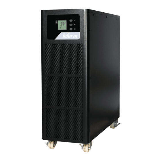
LCD Display ώ With LCD plus LED displays, the user may easily get UPS status and its operational parameters, such as input/output voltage, frequency & load%, battery % and ambient temperature, etc... Intelligent Monitoring Function ώ Via optional SNMP Card, you may remotely control and monitor the UPS. EPO Function ώ... - Page 7 10kVA Rear View 20kVA Rear View (terminal block without (terminal block without cover) cover) LCD panel O/P Switch Maintenance switch Maintenance switch cover RS232 port REPO port Intelligent Slot (SNMP I/P Switch card/ Relay card) Dry contact port (10) Parallel port 1 (11) RS485 port (12)
-
Page 8: Lcd Control Panel
3.3 LCD CONTROL PANEL LCD control panel introduction LED (from top to bottom: “alarm”, “bypass”, “battery”, “inverter”) LCD display Scroll button Off button On button(battery cold start switch) 3.4 INSTALLATION NOTES Note: Consider for the convenience of operation and maintenance, the space in front and back of the cabinet should be left at least 100cm and 80cm respectively when installing the cabinet. -
Page 9: External Protective Devices
WARNING! : Typical battery performance data are quoted for an operating temperature between 20°C and 25°C. Operating it above this range will reduce the battery life while operation below this range will reduce the battery capacity. ώ Should the equipment not be installed immediately it must be stored in a room so as to protect it against excessive humidity and or heat sources. -
Page 10: Power Cables
3.6 POWER CABLES ώ The cable design shall comply with the voltages and currents provided in this sec- tion, Kindly follow local wiring practices and take into consideration the environmental conditions (temperature and physical support media) . WARNING! : Upon starting. Please ensure that you are aware of the location and operation of the external isolators which are connected to the UPS input/bypass supply of the mains distribution panel. -
Page 11: Power Cable Connect
3.7 POWER CABLE CONNECT Once the equipment has been finally positioned and secured, connect the power cables as described in the following procedure. Verify the UPS is totally isolated from its external power source and all power isolators of the UPS are open. Check to see if they are electrically isolated and post any necessary war- ning signs to prevent their inadvertent operation. -
Page 12: Battery Connection
Input A Output A Input B Output B Input C Output C LOAD Input N Output N WARNING: If the load equipment is not ready to accept power on the arrival of the commissioning engineer, then ensure that the system output cables are safely isolated at their ends Connect the safety earth and any necessary bonding earth cables to the copper earth screw located on the floor of the equipment below the power connections. - Page 13 BAT+ BATN BAT- UPS connection terminal block Battery breaker BAT+ BAT- Positive Battery Negative Battery 8(9/10)pieces 8(9/10)pieces 15-20kVA: The UPS adopts positive and negative double battery framework, totally 16pcs (optional 18/20) in series. A neutral cable is retrieved from the joint between the cathode of the 16th (17th/18th/19th/20 th) and the anode of the 17th (18th/19th/20th/21th) of the batteries.
-
Page 14: Ups Parallel Installation
10kVA factory setting of the long-run unit is battery quantity---16pcs, battery capacit- y---12V9AH (charger current 1.35A). When connecting 18/20 batteries, please re-set desi- red battery quantity and its capacity after UPS starts at AC mode. Charger current could be adjusted automatically according to battery capacity selected. All related settings can be done through LCD panel or monitoring software 15-20kVA factory setting of the long-run unit is battery quantity---32pcs, battery capacit- y---12V18AH (charger current 2.7A). -
Page 15: Parallel Cable Installation
Make sure each UPS input breaker is in “off” position and there is no any output from each UPS connected. Battery groups can be connected separately or in parallel, which means the system itself provides both separate battery and common battery. WARNING: Make sure the N, A (L1), B (L2), C (L3) lines are correct, and grounding is well connected. - Page 16 ώ On the main page of Muser4000, click the button of ώ A window of “Software “Append”, then goes to a window of “Append equipment” Parameter Setting” comes out as below, COM choose ac- cording to the UPS , baud rate choose 9600, protocol choose “HIP”, then save this setting.
-
Page 17: Operation
ώ Put the UPS name into “Equip- ment Name”, and UPS’ ID address into “Equipment address”. ώ Click the button “Append”, then the connection between UPS & computer is ac- complished. CAUTION: When the UPS worked on inverter. If you want to use PC to set the output voltage and frequency. - Page 18 ώ Battery mode (Stored Energy Mode) If the AC mains input power fails, the inverter, which obtains power from the battery, supplies the critical AC load. There is no power interruption to the critical load. The UPS will automatically return to Normal Mode when AC recovers. Maintenance bypass switch bypass input Static Bypass...
- Page 19 ώ ECO Mode When the UPS is at AC Mode and the requirement to the load is not critical, the UPS can be set at ECO mode in order to increase the efficiency of the power supplied. At ECO mode, the UPS works at Line-interactive mode, so the UPS will transfer to bypass supply.
-
Page 20: Turn On/Off Ups
4.2 TURN ON/OFF UPS 4.2.1 Restart procedure CAUTION: Make sure grounding is properly done! ώ Set the Battery Breaker to the “ON” for long run UPS. ώ Switch ON the power switch for standard UPS. WARNING: Check to see if the load is safely connected with the output of the UPS. -
Page 21: Test Procedure
4.2.2 Test procedure CAUTION: The UPS is operating normally. It may take 60 seconds to boost up the system and perform self-test completely. ώ Switch off the MAINS to simulate utility failure, the rectifier will turn off and the battery should feed the inverter without interruption. At this time, the LEDs of battery should be turned on. -
Page 22: Cold Start Procedure
Switch ON the output breaker. ώ Switch ON the input breaker. ώ The UPS powers from the static bypass instead of the maintenance bypass, then the bypass LED will light up. Switch OFF the maintenance bypass breaker, then the output is supplied by the static ώ... -
Page 23: Shut Down Procedure
CAUTION: Please press the close start button after 30 seconds until closing the battery switch 4.2.5 Shut down procedure CAUTION: This procedure should be followed to completely shut down the UPS and the LOAD. After all power switches, isolators and circuit breakers are opened, there will be no output. - Page 24 ώ Click “Set” at “User Set” window; ώ At the window of “Data Set”, click “Work Mode”,, choose “Parallel” for the value, then click “Set” as shown in below picture. If the UPS sounds a “beep”, that means the setting is correct.
- Page 25 ώ At the window of “Data Set”, click “Ups ID”, write a value for the parallel UPS ID at the right side, such as “1”, then click “Set” as shown in below picture. If the UPS sounds a “beep”, that means the setting is correct. CAUTION: After changing the parallel system ID, the connection between Muser4000 and equipment might be interrupted.
-
Page 26: The Lcd Display
4.3 THE LCD DISPLAY (1) LED indicator (2) LCD display (3) Scroll button: enter to next item (4) Off button (5) On button Introduction CAUTION: The display provides more functions than those Overview of the operating panel of described in this manual. the UPS There are 17 interfaces available in the LCD display:... - Page 27 When the UPS is connecting with the Utility or Battery at cold start mode, it shows as drawing below: Operational Status and mode (When the UPS at single mode, it shows “NOR” or “ECO”, but If the UPS at paral- lel mode, it shows “PAL”...
- Page 28 6. Bat - (Negative) 7. Backup time 8. Phase A (L1) Output 9. Phase B (L2) Output Voltage/ Voltage/Frequency Frequency 10. Phase C (L3) Output 11. Phase A (L1) Load Capacity Voltage/Frequency...
- Page 29 12. Phase B (L2) Load Capacity 13. Phase C (L3) Load Capacity 14. Total Load Capacity 15. Temperature (battery/Internal and ambient temperature) 16. Software version & model 17. Alarm Code If has battery charging, above 2-13 interface windows will also display the charging status at the same time as below:...
-
Page 30: Parameters Setting
Charging Boost Floating Pressing “scroll” button, you may circulate all messages from the first one to the last one then returns to the first one and vice versa. All alarm codes are present when abnormal behavior(s) occur(s). 4.4 PARAMETERS SETTING The setting function is controlled by 3 buttons (, OFF, ON): ---goes into the setting page and value adjustment;... -
Page 31: Output Voltage Setting
4.4.2 Output voltage setting In the mode setting press “ON” or in frequency setting press “Off”, it goes to the output voltage setting. The output voltage line flashes as in above picture Use button “” to choose the different output volta- ge. -
Page 32: Battery Capacity Setting
4.4.4 Battery capacity setting In the battery capacity setting press “ON” or in bypass voltage upper limit setting press “OFF”, it goes to the battery quantity setting. The battery quantity line flashes as in above picture. Use button “” to choose the different battery capacity. -
Page 33: Bypass Voltage Lower Limit Setting
4.4.7 Bypass voltage lower limit setting In the bypass voltage upper limit setting press “ON” or in parallel ID setting press “OFF”, it goes to the bypass lower limit setting. The bypass lower limit line flashes as in above picture. (“-” for negative, positive does not have any symbol.) Use button “”... -
Page 34: Periodical Battery Self-Test Setting
4.4.9 Periodical battery self-test Setting In the buzzer setting press “ON” or in parallel ID setting press “OFF”, it goes to the battery self-test setting. In the meantime the setting state flashes as above picture shows (Note: ON 1- the battery self-test function is enabled, UPS will do self-test 10 seconds every 30 days;... -
Page 35: Device Address Setting
4.4.11 Device address setting Press “ON” under the battery temperature compensation sensor switch setting or press “OFF” under parallel ID set- ting, goes to the device address setting. The setting state flashes as above picture shows (Note: device add- ress is1~15, it is the MODBUS device address at RS232 & RS485 communication ports. -
Page 36: Parallel Quantity Setting
4.4.13 Parallel quantity setting When under the parallel ID setting press “ON” or when under parallel redundancy quantity setting press “OFF”, it goes to the parallel quantity setting. The parallel quan- tity flashes as in above picture. Use button “” to set the parallel quantity. The parallel quantity range is 2~4. -
Page 37: Parallel System Commissioning
4.5 PARALLEL SYSTEM COMMISSIONING Parallel system should be commissioning when the stand-alone are all intact. Take 4 units in parallel for example. Confirm the input/output wires connection and input phase sequence are correct; switch off the battery breaker and measure the +/- bat voltage of all battery group are normal. -
Page 38: Display Messages/Troubleshooting
Turn on all the battery breaker and confirm the parameter (V/I) are normal. Connected the Load, and check whether the output current is balance. Switch on and off the utility breaker to test all the UPS converters system from Utility to battery and restored function are working find 4.6 DISPLAY MESSAGES/TROUBLESHOOTING This section lists the event and alarm messages that the UPS might display. - Page 39 Alarm Information Fault code UPS Alarm Warning Buzzer (Err) Rectifier Fault Beep continuously Fault LED lit Inverter fault (Including Beep continuously Fault LED lit Inverter bridge is shorted) Inverter Thyristor short Beep continuously Fault LED lit Inverter Thyristor broken Beep continuously Fault LED lit Bypass Thyristor short Beep continuously Fault LED lit Bypass Thyristor broken...
- Page 40 Fault code UPS Alarm Warning Buzzer (Err) Battery over voltage Once per second Fault LED blinking Mains Site Wiring Fault Once per second Fault LED blinking Bypass Site Wiring Fault Once per second Fault LED blinking Output Short-circuit Once per second Fault LED blinking Rectifier over current Once per second...
-
Page 41: Options
4.7 OPTIONS SNMP card: internal SNMP / external SNMP optional Loosen the 2 torque screws (on each side of the card). ώ Carefully pull out the card. Reverse the procedure for re-installation ώ The slot called SNMP supports the MEGAtec protocol. We advise that Net Agent II-3 port is also a tool to remotely monitor and manage any UPS system Net Agent II-3Ports supports the Modem Dial-in (PPP) function to enable the remote control via the internet when the network is unavailable. -
Page 42: Appendix 1 Specifications
Input or Pin Function Description Output Utility Failure Battery Low Bypass On Output UPS Fault Inverter On Summary Alarm Common Remote Shutdown + Input (5~12V) Appendix 1 Specifications Model 10kVA(S/H) 15kVA(S/H) 20kVA(S/H) 10KVA 15KVA 20KVA Capacity 13.5KW 18KW Phase 3 Phase 4 Wires and Ground Rated Voltage 380/400/415Vac Voltage Range... - Page 43 Model 10kVA(S/H) 15kVA(S/H) 20kVA(S/H) 10KVA 15KVA 20KVA Capacity 13.5KW 18KW Phase 3 Phase 4 Wires and Ground Rated Voltage 380/400/415Vac Power Factor Voltage ±1% Regulation Utility ±1%, ±2%, ±4%, ±5%, ±10% of the rated Mode frequency(optional) Frequ- ency Battery (50/60±0.2%) Hz Mode Crest Factor 10kVA...
- Page 44 Model 10kVA(S/H) 15kVA(S/H) 20kVA(S/H) 10KVA 15KVA 20KVA Capacity 13.5KW 18KW Load≤110%: last 60min, ≤125%: last 10min, ≤150%: Mode last 1min, >150% change to bypass immediately Overlo- Bat. Load≤110%: last 10min, ≤125%: last 1min, ≤150%: Mode last 5S, >150% shut down UPS immediately Bypass Breaker 20A Breaker 32A...
-
Page 45: Appendix 2 Problems And Solution
Appendix 2 Problems and Solution In case the UPS cannot work normally, it might be wrong in installation, wiring or operati- on. Please check these aspects first. If all these aspects are checked without any problem, please consult with local agent right away and provide below information. Product model name and serial number. -
Page 46: Appendix 3 Rs232 Communication Port Definition
Problem Possible reason Solution Buzzer long beeps, LCD The UPS output is in short Make sure the load is not in display “29” fault code circuit short circuit, and then restart the UPS. The UPS only works on The UPS is set to ECO Set the UPS working mode bypass mode mode, or the transfer... -
Page 47: Appendix 4 Rs485 Communication Port Definition
PC RS232 port UPS RS232 port Pin 2 Pin 2 UPS send, PC receive Pin 3 Pin 3 PC send, UPS receive Pin 5 Pin 5 ground Available function of RS232 • Monitor UPS power status. • Monitor UPS alarm info. •... -
Page 48: Appendix 5 Bat_T Communication Port Definition
Description device (RJ45) UPS(RJ45) Pin 1/5 Pin 1/5 485+ “A” Pin 2/4 Pin 2/4 485 - “B” Pin7 Pin7 +12Vdc Pin8 Pin8 Available function of RS485 • Monitor UPS power status. • Monitor UPS alarm info. • Monitor UPS running parameters. •... -
Page 49: Appendix 6 Optional Port Definition
Description Temperature senator (RJ45) UPS BAT_T (RJ45) Pin 1/5 Pin 1/5 Pin 2/4 Pin 2/4 Pin 7 Pin 7 Pin 8 Pin 8 Available function of BAT_T • Battery environment temperature monitoring. • Charging voltage modulation depending on batteries’ temperature. Appendix 6 Optional port definition Definition of Male port: Instruction:... -
Page 50: Appendix 7 Repo Instruction
Appendix 7 REPO instruction Definition of port: Connection diagram: Connection between the button and UPS REPO port. Description Button UPS REPO Pin 1 Pin 1 Pin 2 Pin 2 A remote emergency stop switch (Dry contact signal and “normally open” - not ώ... - Page 52 www.informups.com...
Need help?
Do you have a question about the STARK 10 kVA and is the answer not in the manual?
Questions and answers