Table of Contents
Advertisement
Quick Links
Advertisement
Table of Contents

Related Manuals for CDA HCG 731 Series


Summary of Contents for CDA HCG 731 Series
- Page 1 Cooking Hobs Manual for Installation, Use and Maintenance Customer Care Department • The Group Ltd. • Harby Road • Langar • Nottinghamshire • NG13 9HY T : 01949 862 012 F : 01949 862 003 E : service@cda.eu W : www.cda.eu...
-
Page 2: Appliance Information
The CDA Group Ltd cannot be held responsible for injuries or losses caused by incorrect use or installation of this product. Please note that CDA reserve the right to invalidate the guarantee supplied with this product following incorrect installation or misuse of the appliance. -
Page 3: Before Using For The First Time
Important Safeguards and Recommendations – Do not carry out any cleaning or maintenance without first disconnecting the appliance from the electrical supply. – During and after use of the hob, certain parts will become very hot. Do not touch hot parts. –... -
Page 4: Features And Technical Data
– If the hob is used for a prolonged time it may be necessary to provide further ventilation by opening a window or by increasing the suction power of the extractor hood (if fitted). Fig. 1b HCG 731 .. This appliance is class 3... -
Page 5: Gas Burners
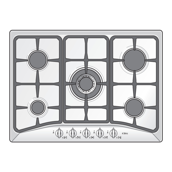
How to Use the Hob Gas Burners Gas flow to the burners is adjusted by turning the knobs (illustrated in fig.2) which control the valves. Turning the knob so that the indicator line points to the symbols printed on the panel achieves the following functions: –... - Page 6 Lighting Gas Burners In order to light the burner, you must: 1 – Press in the corresponding knob and turn counter-clockwise (fig. 3) to the full flame position marked by the symbol and hold the knob in until the flame has been lit. In the case of a mains failure light the burner with a match or lighted taper.
-
Page 7: Choice Of Burner
Choice of Burner The symbols printed on the panel by the side of the knob indicate which burner you are controlling. Choose a suitable burner depending on the cookware diameter and capacity. The pan diameter should be suitable for the burner power to make the most of the burner's high efficiency and not waste fuel. - Page 8 Important: The wok pan stand (fig. 5b - 6b) MUST BE PLACED ONLY over the pan-rest for the triple ring burner. WRONG Fig. 5a WRONG Fig. 6a CORRECT Fig. 5b CORRECT Fig. 6b Model: HCG 731 .. Model: HCG 741 ..
-
Page 9: Cleaning And Maintenance
Cleaning and Maintenance General Tips – Before cleaning the hob switch it off and wait for it to cool down. – Clean with a cloth, hot water and soap or liquid detergent. – Do not use products which are abrasive, corrosive or chlorine based. –... -
Page 10: Burners And Grids
Burners and Grids – These parts can be removed and cleaned with appropriate products. – After cleaning, the burners and their flame spreaders must be well dried and correctly replaced. – It is very important to check that the burner flame spreader and the cap have been correctly positioned. Failure to do so can cause serious problems. - Page 11 Correct Position of Triple Ring Burner The triple ring burner must be correctly positioned (see fig. 9); the burner ribs must be fitted in their housing as shown by the arrow. The burner correctly positioned must not rotate (fig. 10). Then position the cap A and the ring B (figs.
-
Page 12: Tips For Installation
TIPS FOR INSTALLATION Location – The appliance may be installed in a kitchen, Kitchen/diner or a bed sitting room, but not in a room or space containing a bath or a shower. – The appliance must not be installed in a bed-sit room of less than 20m –... -
Page 13: Installation
The two appliances should be connected to the gas supply with independent connections Installation in Kitchen Cabinet with Door It is recommended that a 30mm clearance be left between the cooktop and the fixture surface (fig. 13). Clearance Door Space for connections Fig. - Page 14 – Spread the seal “B” around the left, front and right edges of the cooktop as shown in figure 15c. – Spread the seal “C” along the rear edge of the cooktop as shown in figure 15d. Making sure that the beginning and the end overlap at the seal “B”...
- Page 15 Fastening the Cooktop – Insert the cooktop into the hole and position it correctly. – Adjust the position of the brackets “F" and "R” and tighten screws “B” to block the cooktop firmly in position. – With a sharp cutter or trimmer knife trim the excess sealing material around the edge of the cooktop.
-
Page 16: Gas Supply Requirements
Gas Supply Requirements Important Note This appliance is supplied for use on NATURAL GAS or LPG (check the gas regulation label attached on the appliance). – Appliances supplied for use on NATURAL GAS: they are adjusted for this gas only and cannot be used on any other gas (LPG) without modification. -
Page 17: Gas Connection
The installation must conform to the relevant British Standards. CDA are not legally able to provide any assistance in the installation of gas appliances except to suitably qualified and registered installers. Any suitably qualified and registered fitter requiring help must provide name, address and registration number. -
Page 18: Connection To The Gas Supply
Gas connection The fitting (fig. 17) is made up of: – 1 nut “A” – 1 elbow fitting “C” – gasket “F” Connection to the Gas Supply – Be careful when flexible pipes are used that they do not come into contact with moving parts. –... -
Page 19: Conversion To Natural Gas Or Lpg
Conversion to Natural Gas or LPG Replacing the Burner Injectors If the NATURAL GAS/LPG conversion kit is not supplied with the appliance this kit can be purchased by contacting the After-Sales Service. Choose the injectors to be replaced according to the table below. The injector diameter, expressed in hundredths of a millimetre, is marked on the injector body. -
Page 20: Lubrication Of The Gas Taps
Regulating the Burner Minimum Setting When changing from one type of gas to another, the minimum tap output must also be correct, considering that in this position the flame must be about 4 mm long and must remain lit even when the knob is turned sharply from the maximum to the minimum position. -
Page 21: Mains Electricity Connection
Mains Electricity Connection Incorrect installation may be dangerous and the manufacturer can not be held responsible. Warning! This appliance must be earthed The manufacturer declines all responsibility for any problem caused by failure to observe this rule. THIS APPLIANCE MUST BE CONNECTED TO THE MAINS SUPPLY BY A COMPETENT PERSON, USING FIXED WIRING VIA A DOUBLE POLE SWITCHED FUSE SPUR OUTLET AND PROTECTED BY A 3A FUSE. -
Page 22: Appliance Servicing
Appliance Servicing CDA provide a quality and effective after-sales service to cover all your servicing needs. Please attach your receipt to this page for safekeeping. Please help us to help you by having the following information available when booking a service-call: 1. - Page 23 After the first year and within five years, the parts will be supplied free of charge provided that the repair is carried out by an agent authorised by CDA and the labour will be charged at the commercial rate applicable at the time of repair.
- Page 24 Customer Care Department • The Group Ltd. • Harby Road • Langar • Nottinghamshire • NG13 9HY T : 01949 862 012 F : 01949 862 003 E : service@cda.eu W : www.cda.eu...
Need help?
Do you have a question about the HCG 731 Series and is the answer not in the manual?
Questions and answers