Table of Contents
Advertisement
Quick Links
Advertisement
Table of Contents

Related Manuals for Guilin Woodpecker Medical Instrument Endo Radar Pro


Summary of Contents for Guilin Woodpecker Medical Instrument Endo Radar Pro
- Page 1 Endo Radar Pro Endo Motor INSTRUCTION MANUAL...
-
Page 2: Table Of Contents
Contents 1 Introduction ................... 1 2 Installation and setting ................6 3 Motor alone mode ................1 5 4 Apex locator alone mode ..............1 8 5 Combined length determination mode ..........2 3 6 Trouble shooting ................2 5 7 Cleaning, Disinfection and Sterilization .......... -
Page 3: Introduction
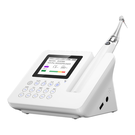
1.2 Introduction Endo Radar Pro is mainly used in Endodontic treatment. It is a cordless endo motor with root canal measurement capability. It can be used as a endo motor for preparation and enlargement of root canals, or device for measuring canal length. - Page 4 1.3 Product configuration 1.3.1 Structure Endo Radar Pro is composed of Motor h andpiece, Contra-angle, measuring wire, USB wire , Power adapter, etc... 1.3.2 Product accessories Motor handpiece Contra-angle Power adapter Base Measuring wire File clip Lip hook Touch probe...
- Page 5 Disposable insulation sleeves 1.4 Indications for use Endo Radar Pro is a cordless endo motor with root canal measurement capability. It can be used as a endo motor for preparation and enlargement of root canals, or device for measuring canal length. It can be used to enlarge the canals while monitoring the position of the file tip inside the canal.
- Page 6 1.7.2 Type of protection against electric shock: Class II equipment with internal power supply 1.7.3 Degree of protection against electric shock: B type applied part 1.7.4 Degree of protection against harmful ingress of water: Ordinary equipment (IPX0) 1.7.5 Degree of safety application in the presence of a flammable anesthetic mixture with air, oxygen, or nitrous oxide: Equipment cannot be used in the presence of a flammable anesthetic mixture with air, oxygen, or nitrous oxide.
- Page 7 commissioned in strict conformity with the EMC information provided in this instruction manual. Specifically, do not use the device close to fluorescent lamp, radio transmitters and remote controls. 1.10.5 Long time use of the device will lead to overheating of the micro motor, let it cold down that use.
-
Page 8: Installation And Setting
power supply.Don't position the device to make it difficult to operate the disconnection device. 2 Installation and setting 2.1 Reset function Use the needle to push the internal button for more than 3 seconds to complete the reset by the reset hole indicated by the arrow below, to solve the accidental crash of the base or accidental failure of the touch button. - Page 9 The contra-angle is free to rotate, adapting to the root canal of different positions, and it is convenient to watch the screen when operating. 2.2.2 Removing When removing the contra-angle, pull it straight out. When inserting and removing the contra-angle, turn the motor handpiece power off beforehand.
- Page 10 2.5 Installation and removal of disposable insulation sleeves 2.5.1 Installation Before each use of the handpiece and after the handpiece is cleaned and disinfected,put on a disposable isolation sleeve. Take the isolation sleeve out of the isolation sleeve box, then insert the isolation sleeve into the motor handpiece from the thin end of the handpiece, and install the isolation sleeve until there is no obvious wrinkle.
- Page 11 5 SET Long press to enter the Contra-angle Calibration and Wireless Match interface In Safety Glide Path mode, switch to choose forward angle or reverse angle 6 LED Wireless charging LED on the base starts to flash, it means wireless charging 7 In Safety Glide Path Mode, increase the angle 8 In Safety Glide Path Mode, decrease the angle 9 SPEED+...
- Page 12 Combined length determination mode parameter setting: 1 SET Touch the button for more than 1 seconds, enter combined length determination mode parameter setting. Touch again, then exit . 2 3 ANGLE +- Set the apical point, it can be set anywhere from 1.0mm to apex(0.0mm) 4 5 SPEED +- Select, “...
- Page 13 Auto apical point reverse The file will reverse when the file tip reaches the apical point. Auto apical point stop The file will stop when the file tip reaches the apical point. Disable apical action function The file rotating as usual even if reach the reference apical point. 2.8.1 The device contains a file library with the preset popular NiTi file systems.
- Page 14 1 SYSTEM Display the selected file system 2 FILE Display the selected file type 3 SPEED Display the rotation speed(applied only to continuous rotation mode)
- Page 15 4 TORQUE Display the limiting value of torque 5 TORQUE BAR Display the limiting value of torque in the bar 6 AUTO REVERSE Display the selected auto reversing protection mode: AUTO REVERSING AUTO STOP AUTO REVERSE OFF 7 Rotational direction Display the rotation direction of device Clockwise continuously rotating Counterclockwise continuously rotating...
- Page 16 10 Display the current remaining battery power of the base Fully charged The remaining battery power is about 70% The remaining battery power is about 30% The battery is very low, please charge in time 11 Display the current Safety Glide Path mode file system number 12 Reverse angle, adjustable from 20°...
-
Page 17: Motor Alone Mode
Note: the description on Safety Glide Path mode is only applicable for the device that has Safety Glide Path mode. 3 Motor alone mode 3.1 Base start and stop 3.1.1 starting: If power off, press and hold the POWER button for several second, welcome screen will appear. - Page 18 3.3.2 AUTO STOP: During operation, if the load exceeds a preset value, The motor reverse automatically and the base alarms .if the load lower the preset value, The motor stops. Push the handpiece button twice to restart the handpiece. 3.3.3 AUTO REVERSE OFF If the load lower the preset value, The motor stops.
- Page 19 range: 0.4-5.0Ncm) 3.7 User-defined system PROGRAM Mode: 8 sets of User-defined continuous rotary system speed and torque parameters can be set, and the user defined file system number (File system number: 1-8) can be switched by the button. Safety Glide Path Mode: 3 sets of User-defined Safety Glide Path system speed, torque, forward angle and reverse angle parameters can be set.
-
Page 20: Apex Locator Alone Mode
After charging, pull out the power adapter. 3.9.2 Motor handpiece charging The motor handpiece has a built-in energy storage lithium battery and is equipped with wireless inductive charging. When the base is in the power-on state, put the motor handpiece correctly in the motor handpiece slot of the base, the wireless charging indicator on the base starts to flash, and the base can start wireless induction charging of the motor handpiece. - Page 21 Picture 1 Attention: a. Please be careful to use the device, keep it stable and avoid hit. Incautious use will lead to the damage or the failure of the machine. b. Measurement cannot be proceeded without the complete insertion of the plug. c.
- Page 22 module. b. Make sure if the plug of the measuring wire is inserted into the socket correctly. c) Make sure if the file clip and lip hook are connected well to the measuring wire. d) Make the lip hook touch the bent wire of the file clip [as showed in picture 3] to confirm all the instruction bars are displayed on the LCD screen and static display the word "OVER", otherwise , it means that the file clip or the measuring wire is damaged, should be replaced.
- Page 23 4.4 Testing the device by tester. (Two weeks test again) User can use the tester to check if the device work properly, specific operation is as follows: a. Pulling out the measure wire and turn off the device. b. Insert the tester c.
- Page 24 of the metal part(near the root canal at the needle handle). If you grip the lower part (bladeor moving part),it will wear the metal part of the file folder and the resin part. [Picture 7] b. When measuring the length of root canal, please don’t use the metal needle file.
-
Page 25: Combined Length Determination Mode
4.7 Cleaning and disinfection 4.7.1 You can use the alcohol or the soap clean the machine and the measuring wire. 4.7.2 Don’t use the chemical reagent. 4.7.3 The lip hook, file clip, touch probe and the contra-angle must be cleaned, disinfected before you start the treatment. WARNNING Measuring wire cannot be clean by high temperature and high pressure. - Page 26 5.2.1 Put the protective silicon cover onto the contra-angle. 5.2.2 Install the contra-angle into the motor handpiece. 5.2.3 Install the file into the contra-angle, clamp the file. 5.2.4 Insert the USB wire’s male plug (small) into the upper side female socket of the motor handpiece. 5.3 Base setting 5.3.1 Touch the “En-Ap”...
-
Page 27: Trouble Shooting
1) Approx 2mm to apical foramen 2) Approx 1mm to apical foramen 3) Approx 0.5mm to apical foramen 4) Apex (apical foramen) WARNNING In the combined length determination mode,If the running time reaches 1 minute, please allow the device to cool down for 1 minute and start again the motor handpiece. - Page 28 Problem Cause Solution After the motor 1. The wireless 1.Press the handpiece “ON/ handpiece is connection has failed OFF” button more than 5 activated, if 2. Handpiece far from seconds to power off and the wireless the base. power on again. communication 2.
-
Page 29: Cleaning, Disinfection And Sterilization
7 Cleaning, Disinfection and Sterilization 7.1 Foreword For hygiene and sanitary safety purposes, the contra-angle, the lip hook, the file clip,the protective silicon cover and the touch probe must be cleaned, disinfected and sterilized before each usage to prevent any contamination. - Page 30 7.3.1 Pre-Op processing Before each use, the handpiece, charger, and base must be cleaned and disinfected. The specific steps are as follows: Warning: The handpiece, charger, and base cannot be cleaned and disinfected with automatic equipment. Manual cleaning and disinfection is required. 7.3.1.1 Manual cleaning steps: 1.
- Page 31 Tools: Nap-free soft cloth, tray 1. Remove the contra-angle from the handpiece, place it in a clean tray, and then remove the disposable isolation sleeve from the handpiece. 2. Soak the nap-free soft cloth with distilled water or deionized water, and then wipe all the surfaces of the components such as the handpiece, charger, base, etc.
- Page 32 sufficiently validated equipment and product-specific procedures are used for cleaning/disinfection and sterilization, and that the validated parameters are adhered to during every cycle. Please also observe the applicable legal requirements in your country as well as the hygiene regulations of the hospital or clinic, especially with regard to the additional requirements for the inactivation of prions.
- Page 33 Disassembling steps a) Press the push-button and pull out the shank/file. b) When removing the protective silicon cover, pull it straight out slowly. c) When inserting and removing the contra-angle, turn thehandpiece power off beforehand. 7.4.3 Cleaning The cleaning should be performed no later than 24 hours after the operation.
- Page 34 b) In washing stage, the water temperature should not exceed 45 °C, otherwise the protein will solidify and it would be difficult to remove. c) After cleaning, the chemical residue should be less than 10mg / L. 7.4.4 Disinfection Disinfection must be performed no later than 2 hours after the cleaning phase.
- Page 35 solution, etc., and only freshly prepared solutions can be used. (c4) During the use of cleaner, the concentration and time provided by manufacturer shall be obeyed. The used cleaner is neodisher MediZym (Dr. Weigert). d) Disinfection: (d1) Direct use after disinfection: temperature ≥ 90 ° C, time ≥...
- Page 36 2. Check the product. If it is obviously damaged, smashed, detached, corroded or bent, it must be scrapped and not allowed to continue to be used. 3. Check the product. If the accessories are found to be damaged, please replace it before use. And the new accessories for replacement must be cleaned, disinfected and dried.
- Page 37 ·The highest sterilization temperature is 138 ° C; ·The sterilization time is at least 4 minutes at a temperature of 132 ° C / 134 ° C and a pressure of 2.0 bar ~ 2.3 bars. ·Allow a maximum sterilization time of 20 minutes at 134 °C. Verification of the fundamental suitability of the products for effective steam sterilization was provided by a verified testing laboratory.
-
Page 38: Storage, Maintenance And Transportation
handle with care; 2. It should not be mixed with dangerous goods during transportation. 3. Avoid exposure to sun or rain or snow during transportation. 8 Storage, maintenance and transportation 8.1 Storage 8.1.1 This equipment should be stored in a room where the relative humidity is 10% ~ 93%, atmospheric pressure is 70kPa to106kPa, and the temperature is -20°C ~ +55°C. -
Page 39: European Authorized Representative
11 European authorized representative 12 Symbol instruction Date of manufacture serial number Type B applied part Manufacturer Ordinary equipment Class Ⅱ equipment Used indoor only Recovery Handle with care Keep dry Power ON / OFF Temperature limitation Atmospheric pressure Humidity limitation for storage Follow Instructions CE marked product... -
Page 40: Emc-Declaration Of Conformity
Table 1: Declaration - electromagnetic emissions Guidance and manufacturer’s declaration - electromagnetic emissions The model Endo Radar Pro is intended for use in the electromagnetic environment specified below. The customer or the user of the model Endo Radar Pro should assure that it is used in such an environment. - Page 41 <5 % UT (>95% dip in UT.) the user of the models power supply (>95% dip in for 1 cycle Endo Radar Pro requires input lines UT.) 70% UT continued operation IEC 61000-4-11 for 1 cycle (30% dip in UT)
- Page 42 Conducted RF & Radiated RF Guidance & Declaration - Electromagnetic immunity The model Endo Radar Pro is intended for use in.the electromagnetic environment specified below. The customer or the user of the models Endo Radar Pro should assure that it is used in such an environment.
- Page 43 To assess the electromagnetic environment due to fixed RF transmitters, an electromagnetic site survey should be considered. If the measured field strength in the location in which the model Endo Radar Pro is used exceeds the applicable RF compliance level above, the model Endo Radar Pro should be observed to verify normal operation.
- Page 44 For transmitters rated at a maximum output power not listed above, the recommended separation distance d in meters (m) can be estimated using the equation applicable to the frequency of the transmitter, where P is the maximum output power rating of the transmitter in watts (W) accordable to the transmitter manufacturer.
- Page 45 ZMN-SM-408 V1.3-20210524...
Need help?
Do you have a question about the Endo Radar Pro and is the answer not in the manual?
Questions and answers