
Related Manuals for PVA FC100-CF


Summary of Contents for PVA FC100-CF
- Page 1 INNOVATION. PRECISION. EXCELLENCE. Film Coat Dispense Valve FC100-CF Operation Manual Revision B...
- Page 2 FC100-CF Manual This document is based on information available at the time of its publication. While efforts have been made to ensure the contents of this manual are accurate, the information contained herein does not purport to cover all specific details or variations in hardware, or to provide for every possible contingency in connection with installation, operation, or maintenance.
-
Page 3: Table Of Contents
FC100-CF Manual Table of Contents PVA Contact Information ......................4 Document History ........................4 System Description ........................5 Nozzle Options ........................... 6 Tool Kit ............................9 Operation ..........................10 Periodic Maintenance ......................10 Routine Cleaning and Disassembly ..................11 Assembly Instructions ......................13 General .......................... -
Page 4: Pva Contact Information
Before you operate this valve, read the operation and setup manual. This will help you to become familiar with the product and ensure successful operation. If any questions or problems arise, contact PVA’s Technical Support department. PVA Contact Information Main Office... -
Page 5: System Description
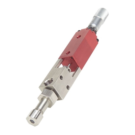
FC100-CF Manual System Description The FC100-CF is a front closing stainless steel film coat dispense valve designed to apply fluids in a non-atomized method to deliver transfer efficiency greater than 99%. This valve is typically used for low viscosity coatings. -
Page 6: Nozzle Options
FC100-CF Manual Nozzle Options The FC100-CF valve is available with a variety of film coat nozzles. All nozzles have a different orifice to allow for a maximum flow rate and a slit to create a fan shaped flow pattern. The width of the fan pattern is determined by the distance from the valve nozzle to the substrate. - Page 7 FC100-CF Manual Safety Due to material contents being under pressure eye protection is required for operators. Refer to MSDS sheets on material being dispensed for other precautions. Page 7 of 23 Revision B February 2022...
-
Page 8: Figure 2: Solenoid Valve
FC100-CF to fit 5/32 in tubing. Note: The valve should normally be in the closed position. Fluid is supplied to the FC100-CF through the 1/8 in fnpt port located on the stainless steel fluid section of the valve. Figure 2: Solenoid Valve... -
Page 9: Tool Kit
FC100-CF Manual Tool Kit PVA offers standard tool kits for all dispensing valves. The tool kit for the FC100-CF includes all necessary tools and lubricating grease to perform maintenance on this dispense valve. Quantity Part Number Description 0266244 8 in Adjustable Wrench... -
Page 10: Operation
(6) can be turned clockwise to lock the adjustment. Periodic Maintenance Refer to Figure 7: FC100-CF Cross Section and Figure 8 for location of parts referenced in the following procedures. 1. Lubricate the packing (16) on the FC100-CF valve every 200 hrs by placing a few drops of mineral oil or other light oil inside the packing nut. -
Page 11: Routine Cleaning And Disassembly
FC100-CF Manual Routine Cleaning and Disassembly Cleaning and rebuilding the valve will be required from time to time. A spare parts kit, Figure 4: FC1-C4-SP Spare Parts Kit, is available with all the normal wear parts included. 1. Begin disassembly by removing air and fluid pressure from the valve. - Page 12 FC100-CF Manual Note: During removal, the spring (11) will force the air section apart. 13. Separate the upper air body (3) from the lower air body (13) to remove the spring (11) then slide the end cap (12) off the needle (2).
-
Page 13: Assembly Instructions
FC100-CF Manual Assembly Instructions General • Lubricate all O-rings with a small amount of silicone grease. • Apply a small amount of removable thread locker to the set screw (10). • Assemble the air section and fluid section separately prior to connecting the assemblies. -
Page 14: Fluid Section
FC100-CF Manual Fluid Section 1. Drop the packing (16) into the fluid section (4), and screw in the packing nut (17), leaving finger tight until assembled with the air section. 2. Mount one 006 Kalrez O-ring (19) on the seat (15) and push the seat into the bottom of the fluid section (4). -
Page 15: Spare Parts
FC100-CF Manual Spare Parts PVA offers standard spare parts kits for all dispensing valves. These kits are stocked for immediate shipment and allow replacement of all wearable parts of the valve. The spare parts kit for the FC100-CF, product number FC1-C4-SP, includes the following... -
Page 16: Drawings
FC100-CF Manual Drawings Figure 5: FC100-CF Dimensions Page 16 of 23 Revision B February 2022... -
Page 17: Figure 6: Fc100-Cf Flow Pattern
FC100-CF Manual Figure 6: FC100-CF Flow Pattern Figure 7: FC100-CF Cross Section Page 17 of 23 Revision B February 2022... -
Page 18: Figure 8: Fc100-Cf Cross Section
FC100-CF Manual Figure 8: FC100-CF Cross Section Figure 9: Micrometer Adjustment Breakdown Page 18 of 23 Revision B February 2022... -
Page 19: Bill Of Materials
FC100-CF Manual Bill of Materials Item and Part Number Description Quantity 1. 114-1658 Nozzletech Adapter 2. 114-5247 FC100 Needle 3. 114-6556 Upper Air Body 4. 114-6933 Fluid Body 5. 114-8053 Nozzle Cap 6. 01423 Micrometer Head 7. 01469 Set Screw, #5 – 40 in x 3/16 in 8. - Page 20 FC100-CF Manual Troubleshooting Troubleshooting Problem Possible Cause Corrective Action Air pressure to the air section Increase the air pressure to is too low 60-100 psi Loosen the packing nut Packing nut is too tight until valve begins to cycle; retighten the packing nut...
- Page 21 FC100-CF Manual The micrometer adjustment Turn the micrometer Dispense rate is too slow bolt is set too close to the adjustment bolt zero mark counterclockwise away from the zero mark Fluid pressure is too low Increase the fluid pressure until the fluid fans out in a...
- Page 22 Unauthorized repair or modification of the enclosed product, and/or the use of spare parts not directly obtained from PVA (or from factory authorized dealers) will void all warranties.
- Page 23 Figure 3: B12-1986 Tool Kit ........................9 Figure 4: FC1-C4-SP Spare Parts Kit ....................15 Figure 5: FC100-CF Dimensions ......................16 Figure 6: FC100-CF Flow Pattern ......................17 Figure 7: FC100-CF Cross Section ...................... 17 Figure 8: FC100-CF Cross Section ...................... 18 Figure 9: Micrometer Adjustment Breakdown .................
Need help?
Do you have a question about the FC100-CF and is the answer not in the manual?
Questions and answers