
Related Manuals for PVA MV250


Summary of Contents for PVA MV250
- Page 1 MV250 POSITIVE DISPLACEMENT VALVE Version: B12-3822 Operation Manual Revision: A January 2013...
- Page 2 This document is based on information available at the time of its publication. While efforts have been made to be accurate, the information contained herein does not purport to cover all details or variations in hardware or software, nor to provide for every possible contingency in connection with installation, operation, or maintenance.
-
Page 3: Preface
Thank you for purchasing the MV250 dispensing valve from PVA. Before attempting to operate the MV250, we recommend that you take a few minutes and read the following operation and setup manual. This will assist in familiarizing you with the product and ensure a successful installation. -
Page 4: Table Of Contents
Table of Contents ............................4 Table of Figures .............................. 4 Theory of Operation ............................5 Air Section ..............................5 Fluid Section ............................... 5 Wetted parts on the MV250 include: ...................... 5 Safety ................................5 Setup ................................5 Tool Kit ................................6 Operation ................................ 7 Air Section .............................. -
Page 5: Theory Of Operation
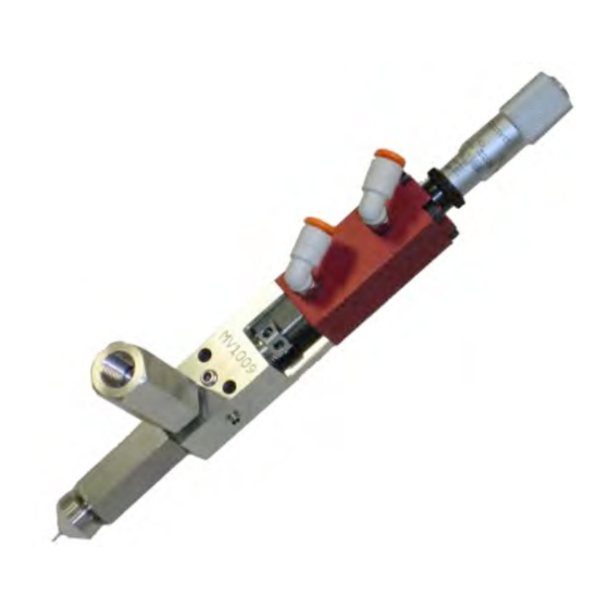
Quick connect air fittings are typically supplied with the MV250 to fit 5/32"od tubing. Note that the valve should be normally in the closed & dispensed position. Fluid is supplied to the MV250 through the 1/8"npt port located on the stainless steel fluid section of the valve. -
Page 6: Tool Kit
Figure 1: Solenoid Valve Tool Kit PVA offers standard tool kits for all dispensing valves. The tool kit for the MV250 is part number B12-1986, which includes all necessary tools and lubricating grease to perform maintenance on this dispense valve. -
Page 7: Operation
Operation Refer to assembly drawings 112-5826_2 and Figure: 3 for part reference numbers. Air Section • Plumb up the valve as outlined above in the Setup procedure. • Regulate the air pressure operating the valve between 60-100psi. • Making sure that the valve is not aimed toward anyone, cycle the valve several times. Note: When the valve is cycling, the piston should be heard hitting the micrometer adjustment (10), and the needle (1) should be seen going up and down in the center. -
Page 8: Setting Dispense Volume
The packing nut (4) may require occasional tightening, as wear occurs in order to prevent leaks through the packing. Routine Cleaning and Disassembly Cleaning and rebuilding the valve will be required from time to time. A spare parts kit, part # MV250-SP is available with all the normal wear parts included. •... - Page 9 • Using the tip of a 3/32" Hex key, loosen the packing nut (4). • Using the same 3/32" Hex key, evenly remove the two machine screws (17) that thread into the fluid body standoffs (7). Note: During removal that there is a spring (11) forcing the air section away from the fluid section. •...
-
Page 10: Assembly Instructions
• All O-rings must be lubricated with a small amount of silicone grease. Note: PVA offers a 2.5cc silicon o-ring lubrication kit; Part#: B62-2048. • A small amount of removable thread locker should be applied to the set screw (18). -
Page 11: Assemble Sections
• Thread the outlet check valve housing (8) onto the bottom of the fluid section (7) and tighten with an adjustable wrench. • ® Place the 007 Kalrez O-ring (27) into the groove of the inlet check valve housing (6). •... -
Page 12: Micrometer Adjustment Breakdown
Micrometer Adjustment Breakdown Figure 3: Micrometer Adjustment Breakdown Reference Section Description Letter Micrometer Wrench Top Screw Dial Micrometer Midsection Collar Micrometer End Figure 4: Micrometer Section Key... -
Page 13: Spare Parts
Spare Parts PVA offers standard spare parts kits for all dispensing valves. These kits are stocked for immediate shipment and allow replacement of all wearable parts of the valve. The spare parts kit for this valve, product number MV25-SP, includes the following components:... -
Page 14: Figure 6: Drawing 112-5826_1
Figure 6: Drawing 112-5826_1... -
Page 15: Figure 7: Drawing 112-5826_2
Figure 7: Drawing 112-5826_2... -
Page 16: Bill Of Materials For Mv250
® VLV-004K 004 Kalrez O-ring ® VLV-006K 006 Kalrez O-ring VLV-007B 007 Buna O-ring ® VLV-007K 007 Kalrez O-ring VLV-014B 014 Buna O-ring * Refer to PVA’s data sheet on Micro Dispense Nozzles for a list of available nozzle options. -
Page 17: Troubleshooting
Troubleshooting Problem Possible Cause Corrective Action Valve does not Air pressure to air section too low Increase air pressure to 60-100 psi cycle Packing nut is too tight Loosen packing nut until valve just begins to cycle, retighten Back out micrometer adjustment by turning it Micrometer adjustment is bottomed out counter-clockwise Disassemble and clean valve... -
Page 18: Pva Warranty Policy
The warranty does not extend to components damaged due to misuse, negligence, or installation and operation that are not in accordance with the recommended factory instructions. Unauthorized repair or modification of the enclosed product, and/or the use of spare parts not directly obtained from PVA (or from factory authorized dealers) will void all warranties.
Need help?
Do you have a question about the MV250 and is the answer not in the manual?
Questions and answers