
Related Manuals for PVA FCS300 Series


Summary of Contents for PVA FCS300 Series
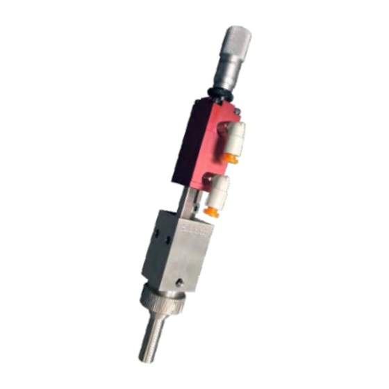
- Page 1 WHERE PRECISION DRIVES PRODUCTIO FCS300-ES-ND FCS300-ES-UF FCS300-ES FCS300-F FCS300-R Front Closing Spray Valve FCS300 Series Operation Manual Rev D...
- Page 2 FCS300 Series Manual This document is based on information available at the time of its publication. While efforts have been made to ensure the contents of this manual are accurate, the information contained herein does not purport to cover all specific details or variations in hardware, or to provide for every possible contingency in connection with installation, operation, or maintenance.
-
Page 3: Table Of Contents
FCS300 Series Manual Table of Contents Introduction ............................5 PVA Contact Information ......................5 Document History ........................5 System Description ........................6 Theory of Operation ......................... 6 Air Section ..........................6 Fluid Section ........................6 Safety ..............................7 Setup ..............................7 Tool Kit ............................ - Page 4 FCS300-F (112-5955) and FSC300-R (112-2195) ........... 28 FCS300-ES (112-2190) ....................29 FCS300-ES-ND (112-2398) ..................30 FCS300-ES-UF (612-9338-1) ..................31 Troubleshooting ..........................32 PVA Warranty Policy ........................33 Table of Figures ..........................34 Page 4 of 34 Revision D June 2020...
-
Page 5: Introduction
Before you operate this valve, read the operation and setup manual. This will help you to become familiar with the product and ensure successful operation. If any questions or problems arise, contact PVA’s Technical Support department. PVA Contact Information Main Office... -
Page 6: System Description
FCS300-ES-UF Front Closing Stainless Steel Spray Valve, Ultra Fine Cap The valves above will be referred to as the FCS300 Series for the purpose of this manual. Any information relevant to a specific valve will be indicated. Theory of Operation The FCS300 Series is a low pressure, low volume, front closing stainless steel spray valve that uses air pressure to atomize fluids and transfer them to a substrate. -
Page 7: Safety
The second option uses a Dual Solenoid configuration to allow independent control of the atomizing air. Fluid is supplied to the FCS300 Series through the 1/8”fnpt port located on the stainless steel fluid section of the valve. -
Page 8: Figure 1: Fcs300-F Diagram
FCS300 Series Manual Figure 1: FCS300-F Diagram Figure 2: FCS300-R Diagram Page 8 of 34 Revision D June 2020... -
Page 9: Figure 3: Fcs300-Es Diagram
FCS300 Series Manual Figure 3: FCS300-ES Diagram Figure 4: FCS300-ES-ND Diagram Page 9 of 34 Revision D June 2020... -
Page 10: Figure 5: Fcs300-Es-Uf Diagram
FCS300 Series Manual Figure 5: FCS300-ES-UF Diagram Page 10 of 34 Revision D June 2020... -
Page 11: Tool Kit
FCS300 Series Manual Tool Kit PVA offers standard tool kits for all dispensing valves. FCS300-F and FCS300-R Tool Kit The tool kit for the FCS300-F and FCS300-R is part number B12-1989, which includes all necessary tools and lubricating grease to perform maintenance on this spray valve. -
Page 12: Fcs300-Es Tool Kit
FCS300 Series Manual FCS300-ES Tool Kit The tool kit for the FCS300-ES is part number B12-2011, which includes all necessary tools and lubricating grease to perform maintenance on this spray valve. B12-2011 Includes: Part Number Description 0266244 8” Adjustable wrench 26563 3/32”... -
Page 13: Fcs300-Es-Nd Tool Kit
FCS300 Series Manual FCS300-ES-ND Tool Kit The tool kit for the FCS300-ES-ND is part number B12-1986, which includes all necessary tools and lubricating grease to perform maintenance on this spray valve. B12-1986 Includes: Part Number Description 0266244 8” Adjustable Wrench 26563 3/32”... -
Page 14: Fcs300-Es-Uf Tool Kit
FCS300 Series Manual FCS300-ES-UF Tool Kit The tool kit for the FCS300-ES-UF is part number B12-1986, which includes all necessary tools and lubricating grease to perform maintenance on this spray valve. B12-1986 Includes: Part Number Description 0266244 8” Adjustable Wrench 26563 3/32”... -
Page 15: Part Reference Numbers
FCS300 Series Manual Part Reference Numbers • FCS300: Refer to Drawing #112-2195 for part reference numbers. • FCS300-ES: Refer to Drawing #112-2190 for part reference numbers. • FCS300-ES-ND: Refer to Drawing #112-2398 for part reference numbers. • FCS300-ES-ND: Refer to Drawing #612-9338-1 for part reference numbers. -
Page 16: Periodic Maintenance
Note: Refer to Troubleshooting section for any problems. Periodic Maintenance 1. Lubricate the packing (14){14}[16]<15> on the FCS300 Series valve every 200 hours by placing a few drops of mineral oil or other light oil inside the packing nut. Note: PVA offers a 10cc mineral oil lubrication kit; Part#: B62-0752 2. - Page 17 FCS300 Series Manual 5. Pull the air section (red anodized portion) away from the fluid section (stainless steel portion). 6. Clean off the tip of the stainless-steel needle (1){1}[1]<3>. 7. From the fluid section of the valve, unthread and remove the packing nut, and the packing (14){14}[16]<15>.
-
Page 18: Assembly Instructions
FCS300 Series Manual Assembly Instructions General • All o-rings must be lubricated with a small amount of silicone grease. • A small amount of removable thread locker should be applied to the set screw (9){9}[11]<10>. • Assemble the air section and fluid section separately prior to connecting the assemblies. -
Page 19: Fluid Section
FCS300 Series Manual Fluid Section 1. Drop the packing (14){14}[16]<15> into the fluid section (3){3}[3]<5>, and screw in the packing nut (15){15}[17]<16> but leave finger tight until assembled with the air section. 2. Mount the 007 Kalrez o-ring (20){21}[21] on the seat (4){4}[4] and thread the seat into the fluid section. -
Page 20: Spare Parts
Spare Parts PVA offers standard spare parts kits for all dispensing valves. These kits are stocked for immediate shipment and allow replacement of all wearable parts of the valve. FCS300-F and FCS300-R Spare Parts Kit The spare parts kit for this valve, product number FCS3-SP, includes the following components. -
Page 21: Fcs300-Es Spare Parts Kit
FCS300 Series Manual FCS300-ES Spare Parts Kit The spare parts kit for this valve, product number FCS3-ES-SP, includes the following components. Part Number Description 114-6937 Seat 114-5249 Needle V305 Packing, Teflon® VLV-014B O-ring, Buna VLV-007B O-ring, Buna VLV-004B O-ring, Buna VLV-007K O-ring, Kalrez®... -
Page 22: Fcs300-Es-Uf Spare Parts Kit
FCS300 Series Manual FCS300-ES-UF Spare Parts Kit The spare parts kit for this valve, product number 612-9786-1, includes the following components. Part Number Description 614-17136-1 Packing 114-5249 Needle VLV-007K O-ring, Kalrez® VLV-007B O-ring, Buna VLV-004B O-ring, Buna VLV-014B O-ring, Buna... -
Page 23: Drawings
FCS300 Series Manual Drawings Figure 16: Drawing 112-5955 (FCS300-F) Page 23 of 34 Revision D June 2020... -
Page 24: Figure 17: Drawing 112-2195 (Fcs300-R)
FCS300 Series Manual Figure 17: Drawing 112-2195 (FCS300-R) Page 24 of 34 Revision D June 2020... -
Page 25: Figure 18: Drawing 112-2190 (Fcs300-Es)
FCS300 Series Manual Figure 18: Drawing 112-2190 (FCS300-ES) Page 25 of 34 Revision D June 2020... -
Page 26: Figure 19: Drawing 112-2398 (Fcs300-Es-Nd)
FCS300 Series Manual Figure 19: Drawing 112-2398 (FCS300-ES-ND) Page 26 of 34 Revision D June 2020... -
Page 27: Figure 20: Drawing 612-9338-1 (Fcs300-Es-Uf)
FCS300 Series Manual Figure 20: Drawing 612-9338-1 (FCS300-ES-UF) Page 27 of 34 Revision D June 2020... -
Page 28: Bill Of Materials
FCS300 Series Manual Bill of Materials FCS300-F (112-5955) and FSC300-R (112-2195) ITEM PART NUMBER DESCRIPTION 114-5248 NEEDLE 114-6556 UPPER AIR BODY 114-6905 FLUID BODY 114-6997 SEAT 01423 MICROMETER HEAD 01469 SET SCREW, #5-40 x 3/16" SHCS #5-40 X 1 3/4"... -
Page 29: Fcs300-Es (112-2190)
FCS300 Series Manual FCS300-ES (112-2190) ITEM PART NUMBER DESCRIPTION 114-5249 NEEDLE 114-6556 UPPER AIR BODY 114-6905 FLUID BODY 114-6937 SEAT 01423 MICROMETER HEAD 01469 SET SCREW, #5-40 x 3/16" SHCS #5-40 X 1 3/4" SOCKET HEAD CAP SCREW SHCS #5-40 X 2"... -
Page 30: Fcs300-Es-Nd (112-2398)
FCS300 Series Manual FCS300-ES-ND (112-2398) ITEM PART NUMBER DESCRIPTION 114-2392 SEAT, ES-ND 114-2393 NARROW DESIGN AIR CAP 114-5249 NEEDLE 114-6556 UPPER AIR BODY 114-6905 FLUID BODY 01423 MICROMETER HEAD 01469 SET SCREW, #5-40 x 3/16" SHCS #5-40 X 1 3/4"... -
Page 31: Fcs300-Es-Uf (612-9338-1)
FCS300 Series Manual FCS300-ES-UF (612-9338-1) Item Part Number Description 114-5249 NEEDLE 114-6556 UPPER AIR BODY 114-6905 FLUID BODY 614-17136-1 SEAT, ES-UF EXTENDED SPRAY ULTRA FINE 614-17260-1 ATOMIZING AIR TIP 614-17284-1 AIR CAP ULTRA FINE UF , INTEGRATED ATOM AIR HOLES... -
Page 32: Troubleshooting
FCS300 Series Manual Troubleshooting Problem Possible Cause Corrective Action • Air pressure to air section is too low • Increase air pressure to 60-100 psi Valve does not cycle • Packing nut is too tight • Loosen packing nut until valve just begins to cycle, retighten •... -
Page 33: Pva Warranty Policy
Unauthorized repair or modification of the enclosed product, and/or the use of spare parts not directly obtained from PVA (or from factory authorized dealers) will void all warranties. -
Page 34: Table Of Figures
FCS300 Series Manual Table of Figures Figure 1: FCS300-F Diagram ......................... 8 Figure 2: FCS300-R Diagram ........................ 8 Figure 3: FCS300-ES Diagram ....................... 9 Figure 4: FCS300-ES-ND Diagram ....................... 9 Figure 5: FCS300-ES-UF Diagram ...................... 10 Figure 6: FCS300-F and FCS300-R Tool Kit ..................11 Figure 7: FCS300-ES Tool Kit .......................
Need help?
Do you have a question about the FCS300 Series and is the answer not in the manual?
Questions and answers