Table of Contents
Advertisement
Advertisement
Table of Contents

Related Manuals for BK Precision 1856D


Summary of Contents for BK Precision 1856D
- Page 1 Instruction Manual Model 1856D 3.7GHz Frequency Counter...
- Page 2 WARRANTY Warranty service covers a period of one year from the date of original purchase. In case of technical failure within one year, repair service will be provided by our service center or sales outlet free of charge. We charge customers for repairs after the one-year warranty period has expired. We charge for repairs regardless of the warranty period if failure resulted from the user’s negligence, natural disaster or accident.
- Page 3 Introduction Thank you for purchasing our product. Electronic measuring instruments produced by us are high technology products made under strict quality control. We guarantee their exceptional precision and utmost reliability. For proper use of the product, please read this operation manual carefully. Note To maintain the full precision and reliability of this product, use it within the temperature range of 10 °C to 35 °C (50...
-
Page 4: Table Of Contents
CONTENTS 1. PRODUCT DESCRIPTION 1-1. Introduction ----------------------------------------------------- (5) 1-2. Technical Specifications ------------------------------------ 1-3. Equipment Ratings ------------------------------------------- 1-4. Supplied Accessories ---------------------------------------- (10) 2. INSTALLATION 2-1. Initial Inspection ----------------------------------------------- (10) 2-2. Connecting AC Power --------------------------------------- (10) 2-3. Cooling and Ventilation -------------------------------------- (10) 2-4. -
Page 5: Introduction
1-1. Introduction This reciprocal FREQUENCY COUNTER is a microprocessor-controlled instrument for frequency measurement. Due to uniquely developed LSI circuitry in an expanding/reciprocal system, high accuracy with 9-digit resolution is achieved with a one second gate time. It covers a frequency range of from 0.1 Hz to 3.5 GHz based on a 10 MHz TCO (Temperature Controlled Oscillator). -
Page 6: Technical Specifications
1-2. Technical Specifications g INPUT A CHARACTERISTICS h FREQUENCY RANGE: 0.1 Hz to 100 MHz (DC coupled) 30 Hz to 100 MHz (AC coupled) h SENSITIVITY: 30 mV rms h COUPLING: AC or DC selectable. h IMPEDANCE: 1 MΩ resistance shunted by < 40 pF h ATTENUATOR: x1 or x10 switch selectable h LOW PASS FILTER:... - Page 7 h Max. Input Voltage Level 3 0 0 2 5 0 2 0 0 1 5 0 1 0 0 1 0 0 5 0 0 1 0 M 5 0 M 1 0 0 M F R E Q U E N C Y ( H z ) FIG.
- Page 8 h Resolution and Number of Displayed Digits Time Base Selector Gate Time 0.01S 0.1S Number Of Displayed Digits Frequency (Input C) RESOLUTION 100 MHz-999 MHz 10 KHz 1 KHz 1 KHz 100 Hz 100 Hz 10 Hz 10 Hz 1 Hz 1 GHz-3.7 GHz 100 KHz 10 KHz...
-
Page 9: Equipment Ratings
h GATE TIME: Depending on input frequency < 10 mS----------- Somewhere between 0.9 and 9mS < 0.1 S------------- Somewhere between 9 and 90mS < 1 S----------------Somewhere between 90 and 900mS < 10 S---------------Somewhere between 0.9 and 9S NOTE: LAST MEASUREMENT DISPLAY WILL REMAIN FOR 10 SECONDS AFTER SIGNAL OFF. -
Page 10: Supplied Accessories
1-4. Supplied Accessories User’s Manual --------------------------------------------------------------1 BNC cable -------------------------------------------------------------------1 Power cord-------------------------------------------------------------------1 Spare Fuse-------------------------------------------------------------------1 2. INSTALLATION 2-1. Initial Inspection This instrument was carefully inspected both mechanically and electrically before shipment. It should be physically free of damage. To confirm this, the instrument should be inspected for physical damage which may have occurred in transit. -
Page 11: Warming-Up
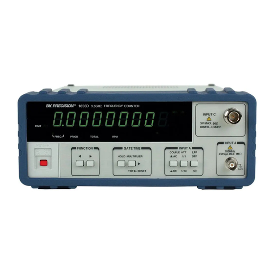
2-5. Warming-Up Allow at least 30 minutes for the unit to warm up so that it can stabilize. 3. OPERATION 3-1. Controls, Indicators and Connectors T X 0 . n H z I NP UT C SE C 3V M AX. R M T 8 0 M H z 7 G H z... - Page 12 UNIT INDICATOR: When lit, indicates that the frequency displayed is in MHz, KHz, Hz and period is in nano, micro, or milli (n/u/m) Sec. HOLD INDICATOR: The HOLD function is engaged the when lit. INPUT C: Use this input for all frequency measurements above 80 MHz.
- Page 13 the GATE TIME. d. TOTAL A: When this mode is selected, the unit counts the cycles of the signal at input A and continuously displays that count. e. RPM A: When this mode is selected, the unit displays the RPM (Revolutions Per Minute) of the signal at input A.
-
Page 14: Operating Instructions
base signal can be monitored or through which an external time base signal can be applied (see item above). The external signal should have a voltage range of 1.5 V~5 V rms. RS-232C CONNECTOR: Connector for serial interfacing with a computer. 3-2. - Page 15 Engaging the HOLD switch “freezes” the display at the existing reading. When HOLD is released, the display is updated and resumes counting. Engage the ATTENUATOR if necessary. When set to x10 (pushed in), the signal at input A is attenuated by a factor of approximately 10 before it is applied to the counter.
-
Page 16: Period Measurements
3-4. Period Measurements Apply the signal to be measured at input A. Select the resolution using the GATE TIME selector switch. The period is indicated on the display. The gate indicator is lit while the measurement is in progress. The ATTENUATOR, LPF, and COUPLING switches operate the same as they do in the frequency measurements modes. -
Page 17: Use Of Rs-232C Serial Interfacing
3-7. Use of RS-232C Serial Interfacing 1) Hardware/Software Requirements IBM PC/XT/AT or compatible computer Microsoft Windows Serial port for connection with counter 2) Output Data Formats (1) Baud rate : 9600BPS 1 start bit (0) 8 data bit 1 stop bit (1) NONE PARITY (2) To Frequency counter Command... -
Page 18: Maintenance
3) Installing program and using the software: Refer to the “Readme” file on the software diskette supplied with unit. 4. MAINTENANCE CAUTION FOR SAFETY, IT IS ESSENTIAL TO PROPERLY MAINTAIN AND SERVICE THIS INSTRUMENT WARNING VOLTAGES WITHIN THIS INSTRUMENT ARE SUFFICIENTLY HIGH TO BE LETHAL. -
Page 19: Other
around the window cover areas where water could leak into the instrument while drying. 5. OTHER 5-1. BNC Cable Considerations The accuracy of radio frequency measurements can be affected by the connections between the signal source and counter. The main issues involved are standing waves and cable shunt capacitance. -
Page 20: Attenuator Probes
5-2. Attenuator Probes When measuring signals at input A that will exceed its maximum input voltage level (See FIG. 1), a 10:1 attenuating probe such as an oscilloscope probe should be used. NOTE DO NOT USE A 10:1 PROBE WITH THE INPUT C. THESE PROBES ARE DESIGNED WITH A 10:1 ATTENUATION FOR AN INSTRUMENT WITH AN INPUT RESISTANCE OF 1 M Ω. - Page 21 Limited One-Year Warranty B&K Precision Corp. warrants to the original purchaser that its product and the component parts thereof, will be free from defects in workmanship and materials for a period of one year from the data of purchase. B&K Precision Corp. will, without charge, repair or replace, at its’ option, defective product or component parts.
- Page 22 Service Information Warranty Service: Please return the product in the original packaging with proof of purchase to the below address. Clearly state in writing the performance problem and return any leads, connectors and accessories that you are using with the device. Non-Warranty Service: Return the product in the original packaging to the below address.
- Page 23 22820 Savi Ranch Parkway Yorba Linda, CA 92887 PN: 481-532-9-001 TEL: 714-921-9095 Printed in Korea FAX: 714-921-6422...
Need help?
Do you have a question about the 1856D and is the answer not in the manual?
Questions and answers