Advertisement
Quick Links
414720
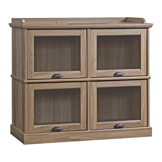
Highboy TV Stand
Barrister Lane Collection
PLEASE CONTACT US
BEFORE RETURNING
YOUR UNIT TO THE STORE
1-800-523-3987
www.sauder.com
NOTE: THIS INSTRUCTION BOOKLET CONTAINS
IMPORTANT SAFETY INFORMATION.
PLEASE READ AND KEEP FOR FUTURE REFERENCE.
English .................... Page 1-22
Français ...............Pages 23-25
Made in the USA
Espanol .............Páginas 26-28
Archbold, OH
Lot #: 350556
Date Purchased: ____________________
04 / 22 / 13
Advertisement

Related Manuals for Sauder 414720


Summary of Contents for Sauder 414720
- Page 1 414720 Highboy TV Stand Barrister Lane Collection NOTE: THIS INSTRUCTION BOOKLET CONTAINS IMPORTANT SAFETY INFORMATION. PLEASE CONTACT US PLEASE READ AND KEEP FOR FUTURE REFERENCE. BEFORE RETURNING English ....Page 1-22 YOUR UNIT TO THE STORE Français ....Pages 23-25 Made in the USA 1-800-523-3987 Espanol .....Páginas 26-28...
- Page 2 • Check the size and weight of your TV. Compare it to the diagram below – before you begin assembly! • This Sauder unit is designed for use with televisions weighing less than 50 pounds. Never use with a TV that weighs more.
- Page 3 Use this PART IDENTIFICATION to help identify similar parts. RIGHT END BOTTOM LEFT MOLDING LEFT END SHELF FRONT BASE LOWER RIGHT END BACK SIDE BASE LOWER LEFT END BRACE SIDE RAIL UPRIGHT DOOR BACK RAIL LOWER UPRIGHT FRONT MOLDING RIGHT MOLDING 414720 www.sauder.com/services Page 3...
- Page 4 SILVER 1-1/8" FLAT HEAD SCREW - 7 BROWN 1" FLAT HEAD SCREW - 4 SILVER 5/8" MACHINE SCREW - 2 GOLD 1" MACHINE SCREW - 8 Screws are shown actual size. You may receive extra hardware with your unit. Page 4 www.sauder.com/services 414720...
- Page 5 Push sixteen HIDDEN CAMS (1F) into the ENDS (A and B), LOWER ENDS (C and D), UPRIGHTS (E and F), and BOTTOM (H). Then, insert the metal end of a CAM DOWEL (2F) into each HIDDEN CAM, except in the ENDS (A and B). 414720 www.sauder.com/services...
- Page 6 BROWN 7/16" LARGE HEAD SCREW (12 used in this step) Fasten eight DOOR SLIDES (37M) to the ENDS (A and B), LOWER ENDS (C and D), and UPRIGHTS (E and F). Use twelve BROWN 7/16" LARGE HEAD SCREWS (6S). Page 6 www.sauder.com/services 414720...
- Page 7 BLACK 1-7/8" FLAT HEAD SCREW (7 used in this step) Fasten the RAILS (R and S) to the TOP (G). Use seven BLACK 1-7/8" FLAT HEAD SCREWS (2S). 414720 www.sauder.com/services Page 7...
- Page 8 Use your hammer to tap the MOLDING CONNECTOR (19F) into the notches in the MOLDINGS. Flat end Flat end Tap two MOLDING CONNECTORS (19F) into the notches in the MOLDINGS (M, N and O). Page 8 www.sauder.com/services 414720...
- Page 9 SILVER 1-1/8" FLAT HEAD SCREW (7 used in this step) Finished surface Fasten the MOLDINGS (M, N and O) to the TOP (G). Use seven SILVER 1-1/8" FLAT HEAD SCREWS (10S). 414720 www.sauder.com/services Page 9...
- Page 10 Turn four CAM SCREWS (8F) into the MOLDINGS (N and O). Page 10 www.sauder.com/services 414720...
- Page 11 Tighten Arrow Risk of damage or injury. Hidden Cams must be completely Arrow Maximum tightened. Hidden 210 degrees Cams that are not completely tightened Minimum may loosen, and parts 190 degrees may separate. To completely tighten: 414720 www.sauder.com/services Page 11...
- Page 12 BLACK 1-7/8" FLAT HEAD SCREW (6 used in this step) Fasten the SHELF (I) to the ENDS (A and B) and UPRIGHT (E). Use six BLACK 1-7/8" FLAT HEAD SCREWS (2S). Page 12 www.sauder.com/services 414720...
- Page 13 S u r Finished edge H I D Maximum Arrow 210 degrees Minimum 190 degrees Fasten the LOWER ENDS (C and D) and LOWER UPRIGHT (F) to the SHELF (I). Tighten six HIDDEN CAMS. 414720 www.sauder.com/services Page 13...
- Page 14 210 degrees Minimum 190 degrees Fasten the BOTTOM (H) to the LOWER ENDS (C and D). Tighten four HIDDEN CAMS. Fasten the BOTTOM (H) to the LOWER UPRIGHT (F). Use two BLACK 1-7/8" FLAT HEAD SCREWS (2S) Page 14 www.sauder.com/services 414720...
- Page 15 Fasten eight ANGLE BRACKETS (5G) to the LOWER ENDS (C and D), BOTTOM (H), and BRACE (K). Use eight BLACK 9/16" LARGE HEAD SCREWS (1S). NOTE: Be sure the edges of the ANGLE BRACKETS are even with the edges of the ENDS, BOTTOM, and BRACE. 414720 www.sauder.com/services Page 15...
- Page 16 (4 used for the BRACKETS) Carefully turn your unit over onto its front edges. Fasten the BRACE (K) to the LOWER ENDS (C and D) and BOTTOM (H). Use four BLACK 9/16" LARGE HEAD SCREWS (1S). Page 16 www.sauder.com/services 414720...
- Page 17 Fasten the BACK (J) to your unit using the NAILS (1N). NOTE: Be sure to tap NAILS into the holes that line up over the SHELF (I). NOTE: Perforations have been provided for access through the BACK. Carefully cut out the holes needed. 414720 www.sauder.com/services Page 17...
- Page 18 Fasten the FRONT BASE (P) to the ENDS (C and D) and BOTTOM (H). Use four BLACK 9/16" LARGE HEAD SCREWS (1S). Fasten the SIDE BASES (Q) to the LOWER ENDS (C and D). Use four BROWN 1" FLAT HEAD SCREWS (12S). Page 18 www.sauder.com/services 414720...
- Page 19 Push the RUBBER SLEEVES (2R) over the METAL PINS (1R). Insert the METAL PINS into the holes in the ENDS (A, B, C and D) and UPRIGHTS (E and F). These are used for door stops when the DOORS are open. 414720 www.sauder.com/services...
- Page 20 Fasten a PULL (70K) to a DOOR (L). Use two GOLD 1" MACHINE SCREWS (50S). Fasten two DOOR HANGERS (40G) to the DOOR. Use two BLACK 9/16" LARGE HEAD SCREWS (1S). Repeat this step for the other DOORS. Page 20 www.sauder.com/services 414720...
- Page 21 HANGERS behind the large hole on the DOOR SLIDES. Push the door into the unit horizontally. While holding the DOOR, swing the DOOR SLIDE up into place and fasten it using a BROWN 7/16" LARGE HEAD SCREW (6S). Repeat this step to hang the remaining DOORS. 414720 www.sauder.com/services Page 21...
- Page 22 NOTE: This is a permanent label intended to last for the life of the product. Once applied, do not try to remove it. NOTE: Please read the back pages of the instruction booklet for important safety information. This completes assembly. Clean with your favorite furniture polish or a damp cloth. Wipe dry. Page 22 www.sauder.com/services 414720...
- Page 23 TRAVERSE LATÉRALE ......2 et conserver le livret TRAVERSE ARRIÈRE ......1 pour future référence. EXCENTRIQUE ESCAMOTABLE ..16 Pour contacter Sauder en ce qui concerne cet CHEVILLE D'EXCENTRIQUE ..... 12 élément, faire référence VIS D'EXCENTRIQUE ......4 au numéro de lot et CONSOLE À...
- Page 24 Utiliser sept VIS TÊTE PLATE 28 mm ARGENT (10S). au diagramme ci-dessous avant de commencer l'assemblage ! ÉTAPE 6 • Cette unité Sauder est conçue pour les téléviseurs pesant moins de 22,6 kg. Ne jamais utiliser avec des Faire tourner quatre VIS D'EXCENTRIQUE (8F) dans téléviseurs plus lourds.
- Page 25 REMARQUE : Prière de lire les informations importantes sur la sécurité fi gurant sur les pages arrière du manuel d’instructions. Ceci complète l'assemblage. Nettoyer à l’aide d’une encaustique pour meubles ou d’un chiffon humide. Essuyer. 414720 www.sauder.com/services Page 25...
- Page 26 BORDE ELEVADO POSTERIOR ..1 EXCÉNTRICO ESCONDIDO ....16 Si necesita ponerse en contacto con PASADOR DE EXCÉNTRICO ..... 12 Sauder en cuanto a BIELA DE EXCÉNTRICO ...... 4 esta unidad, refi érase SOPORTE ANGULAR ......8 al número de lote y 19F CONECTOR DE MOLDURA ....
- Page 27 MOLDURAS (M, N y O). diagrama abajo - antes de comenzar el ensamblaje! • Esta unidad Sauder está diseñada para ser usada con PASO 5 televisores cuyo peso sea inferior a 22,6 Kg. Nunca la use para un televisor de mayor peso.
- Page 28 Fije las BASES LATERALES (Q) a los EXTREMOS Esto completa el ensamblaje. Limpie con su pulimento INFERIORES (C y D). Utilice cuatro TORNILLOS para muebles preferido o un paño húmedo. Seque con MARRONES DE CABEZA PERDIDA de 25 mm (12S). un paño. Page 28 www.sauder.com/services 414720...
- Page 29 équipé. • Blessure physique. Le mobilier peut être mobilier. très lourd. • Ne pas pousser le mobilier, surtout sur la moquette. Se faire aider par une autre personne pour soulever l’élément et le mettre en place. 414720 www.sauder.com/services Page 29...
- Page 30 • Lesión física. El mobiliario puede ser • No empuje la unidad, especialmente muy pesado. sobre un piso alfombrado. Pide la ayuda de otra persona en levantar la unidad y colocarla en lugar. Page 30 www.sauder.com/services 414720...
- Page 31 4. La présente garantie ne s’applique qu’aux défauts garantis qui se produisent des composantes de mobilier Sauder. Le mot « défaut », tel qu’il est utilisé sous pour la première fois et qui sont signalés à Sauder dans les limites de ouverture les termes de la présente garantie, comprend les imperfections des pièces qui...
- Page 32 Archbold, Ohio, where it all began. Certifi cate of Conformity The Sauder name on the box ensures that 1. This certifi cate applies to the Sauder Woodworking Product identifi ed by this Instruction Book. the item you have purchased is made with 2.
Need help?
Do you have a question about the 414720 and is the answer not in the manual?
Questions and answers