Advertisement
Quick Links
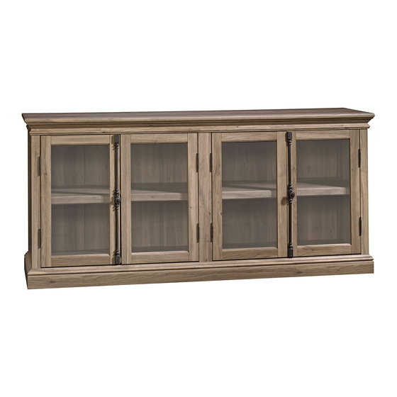
414721
Storage Credenza
Barrister Lane Collection
PLEASE CONTACT US
BEFORE RETURNING
YOUR UNIT TO THE STORE
1-800-523-3987
www.sauder.com
NOTE: THIS INSTRUCTION BOOKLET CONTAINS
IMPORTANT SAFETY INFORMATION.
PLEASE READ AND KEEP FOR FUTURE REFERENCE.
English .................... Page 1-22
Français ...............Pages 23-25
Made in the USA
Espanol .............Páginas 26-28
Archbold, OH
Lot #: 350044
Date Purchased: ____________________
04 / 05 / 13
Advertisement

Related Manuals for Sauder Barrister Lane Storage Credenza 414721


Summary of Contents for Sauder Barrister Lane Storage Credenza 414721
- Page 1 PLEASE READ AND KEEP FOR FUTURE REFERENCE. BEFORE RETURNING English ....Page 1-22 YOUR UNIT TO THE STORE Français ....Pages 23-25 Made in the USA 1-800-523-3987 Espanol .....Páginas 26-28 Archbold, OH www.sauder.com Lot #: 350044 04 / 05 / 13 Date Purchased: ____________________...
- Page 2 • Check the size and weight of your TV. Compare it to the diagram below – before you begin assembly! • This Sauder unit is designed for use with televisions weighing less than 135 pounds. Never use with a TV that weighs more.
-
Page 3: Part Identification
Use this PART IDENTIFICATION to help identify similar parts. RIGHT BASE UPRIGHT LEFT BASE BASE BOTTOM FRONT MOLDING BACK RIGHT MOLDING CENTER BACK LEFT MOLDING LARGE BACK END MOLDING DOOR UPRIGHT MOLDING INNER DOOR SHELF MOLDING ADJUSTABLE SHELF BRACE 414721 www.sauder.com/services Page 3... -
Page 4: Hardware Identification
BLACK 1/2" FLAT HEAD SCREW - 4 SILVER 5/8" MACHINE SCREW - 4 BLACK 9/16" PAN HEAD SCREW - 4 SILVER 1-1/2" MACHINE SCREW - 2 Screws are shown actual size. You may receive extra hardware with your unit. Page 4 www.sauder.com/services 414721... - Page 5 Assemble your unit on a carpeted fl oor or on the empty carton to avoid scratching your unit or the fl oor. ® To begin assembly, push a SAUDER TWIST-LOCK FASTENER (10F) into the large holes in the MOLDINGS (O and P).
- Page 6 Push twenty-four HIDDEN CAMS (1F) into the ENDS (A), UPRIGHT (B), BOTTOM (D), and BRACES (T). Then, insert the metal end of a CAM DOWEL (2F) into each HIDDEN CAM, except the short edges of the ENDS (A) and BRACES (T). Page 6 www.sauder.com/services 414721...
- Page 7 (12 used) Turn twelve CAM SCREWS (8F) into the BASES (K and L) and MOLDINGS (N, O, and P). 414721 www.sauder.com/services Page 7...
- Page 8 Tighten Arrow Risk of damage or injury. Hidden Cams must be completely Arrow Maximum tightened. Hidden 210 degrees Cams that are not completely tightened Minimum may loosen, and parts 190 degrees may separate. To completely tighten: Page 8 www.sauder.com/services 414721...
- Page 9 ® How to use the SAUDER TWIST-LOCK FASTENER 1. Insert the dowel end of the FASTENER into the hole of the adjoining part. NOTE: The dowel end of the FASTENER must remain fully inserted in the hole of the adjoining part while locking the FASTENER.
- Page 10 Fasten the FRONT MOLDING (N) to the TOP (C) and MOLDINGS (O and P). Use six BLACK 9/16" LARGE HEAD SCREWS (1S) through the METAL BRACKETS (4G) and CORNER BRACKETS (31G) and into the FRONT MOLDING. Page 10 www.sauder.com/services 414721...
- Page 11 Push a SMALL MAGNETIC CATCH (2I) into the center hole in each BRACE (T). Fasten a MAGNETIC CATCH (12I) to each BRACE (T). Use four BLACK 9/16" PAN HEAD SCREWS (51S). NOTE: Pay close attention to the positioning of the MAGNETIC CATCHES (12I). Follow the diagram. 414721 www.sauder.com/services Page 11...
- Page 12 Fasten the UPRIGHT (B) to the TOP (C). Tighten two HIDDEN CAMS. Fasten the UPRIGHT (B) to the FRONT MOLDING (N). Use a METAL BRACKET (4G) and two BLACK 9/16" LARGE HEAD SCREWS (1S). Fasten the UPRIGHT MOLDING (R) to the UPRIGHT (B). Tighten two HIDDEN CAMS. Page 12 www.sauder.com/services 414721...
- Page 13 Fasten the LEFT END (A) to the LEFT MOLDING (P). Tighten two HIDDEN CAMS. Insert two METAL PINS (1R) into the CENTER BACK (F). Insert the METAL PINS (1R) in the CENTER BACK (F) into the holes in the TOP (C). 414721 www.sauder.com/services Page 13...
- Page 14 Minimum 190 degrees Fasten the BOTTOM (D) to the LEFT BASE (L). Tighten two HIDDEN CAMS. Fasten the BOTTOM (D) to the UPRIGHT (B) and CENTER BACK (F). Use three BLACK 1-7/8" FLAT HEAD SCREWS (2S). Page 14 www.sauder.com/services 414721...
- Page 15 Insert four METAL PINS (1R) into the TOP (C). Insert the METAL PINS (1R) in the TOP (C) into the holes in the BACKS (E). Fasten the BACKS (E) to the BOTTOM (D). Use two BLACK 1-7/8" FLAT HEAD SCREWS (2S). 414721 www.sauder.com/services Page 15...
- Page 16 S u r H I D Maximum Arrow 210 degrees Minimum 190 degrees Fasten the RIGHT END (A) to the RIGHT MOLDING (O) and BOTTOM (D) to the RIGHT BASE (K). Tighten four HIDDEN CAMS. Page 16 www.sauder.com/services 414721...
- Page 17 NOTE: Be sure the BRACKETS are even with the edge of the BOTTOM. Fasten the BASE (M) to the BOTTOM (D) and BASES (K and L). Use seven BLACK 9/16" LARGE HEAD SCREWS (1S) through the METAL BRACKETS (4G) and CORNER BRACKETS (31G) and into the BASE. 414721 www.sauder.com/services Page 17...
- Page 18 LARGE BACKS to your unit using the NAILS (1N). NOTE: Position perforations as shown. Perforations have been provided for access through the BACK. Carefully cut out the holes needed. Push the FOOT (23E) into the hole in the BOTTOM (D). Page 18 www.sauder.com/services 414721...
- Page 19 BLACK 9/16" LARGE HEAD SCREW (16 used in this step) Fasten two HINGES (27H) to each DOOR (H and I). Use sixteen BLACK 9/16" LARGE HEAD SCREWS (1S). NOTE: The HINGES should be positioned exactly as shown. 414721 www.sauder.com/services Page 19...
- Page 20 Fasten a STRIKE PLATE (6I) to each DOOR (H and I). Use two BLACK 1/2" FLAT HEAD SCREWS (11S). Repeat this step for the other DOORS (H and I). Fasten DOOR (I) to the MOLDING (R) and fasten DOOR (H) to the other MOLDING (Q). Page 20 www.sauder.com/services 414721...
- Page 21 Push the RUBBER SLEEVES (2R) over the remaining METAL PINS (1R). Insert the METAL PINS into the hole locations of your choice in the ENDS (A) and UPRIGHT (B). Set the ADJUSTABLE SHELVES (J) onto the METAL PINS. *U.S. Patent No. 5,499,886 414721 www.sauder.com/services Page 21...
- Page 22 Push a CAM COVER (13P) onto each visible HIDDEN CAM. NOTE: Please read the back pages of the instruction booklet for important safety information. This completes assembly. Clean with your favorite furniture polish or a damp cloth. Wipe dry. Page 22 www.sauder.com/services 414721...
-
Page 23: Liste De Pièces
CLOU ..........16 et conserver le livret 13P COUVERCLE D'EXCENTRIQUE ..14 pour future référence. GOUPILLE EN MÉTAL ....14 Pour contacter Sauder MANCHON EN CAOUTCHOUC ..8 en ce qui concerne cet élément, faire référence VIS TÊTE LARGE 14 mm NOIRE ..93 au numéro de lot et VIS TÊTE PLATE 48 mm NOIRE ..6... - Page 24 ! 2. Bien serrer la FIXATION à l'aide d'un tournevis Phillips. • Cette unité Sauder est conçue pour les téléviseurs Fixer les MOULURES (O et P) au DESSUS (C). Serrer pesant moins de 61 kg. Ne jamais utiliser avec des deux FIXATIONS TWIST-LOCK®.
- Page 25 fi gurant sur les pages arrière du manuel Utiliser seize VIS TÊTE LARGE 14 mm NOIRES (1S). d’instructions. REMARQUE : Positionner les CHARNIÈRES comme il Ceci complète l'assemblage. Nettoyer à l’aide d’une l’est indiqué. encaustique pour meubles ou d’un chiffon humide. Essuyer. 414721 www.sauder.com/services Page 25...
-
Page 26: Lista De Partes
CABEZA PERDIDA de 48 mm ..6 en contacto con 10F SUJETADOR TWIST-LOCK® ..2 11S TORNILLO NEGRO DE Sauder en cuanto a CABEZA PERDIDA de 13 mm ..4 esta unidad, refi érase 15S TORNILLO PLATEADO PARA al número de lote y METAL de 16 mm ......4... - Page 27 - antes de comenzar el ensamblaje! un destornillador Phillips (cruz). • Esta unidad Sauder está diseñada para ser usada con Fije las MOLDURAS (O y P) al PANEL SUPERIOR (C). televisores cuyo peso sea inferior a 61 Kg. Nunca la use Apriete dos SUJETADORES TWIST-LOCK®.
- Page 28 Utilice dieciséis TORNILLOS NEGROS DE CABEZA seguridad. GRANDE de 14 mm (1S). Esto completa el ensamblaje. Limpie con su pulimento NOTA: Coloque las BISAGRAS exactamente como se para muebles preferido o un paño húmedo. Seque con muestra. un paño. Page 28 www.sauder.com/services 414721...
- Page 29 équipé. • Blessure physique. Le mobilier peut être mobilier. très lourd. • Ne pas pousser le mobilier, surtout sur la moquette. Se faire aider par une autre personne pour soulever l’élément et le mettre en place. 414721 www.sauder.com/services Page 29...
- Page 30 • Lesión física. El mobiliario puede ser • No empuje la unidad, especialmente muy pesado. sobre un piso alfombrado. Pide la ayuda de otra persona en levantar la unidad y colocarla en lugar. Page 30 www.sauder.com/services 414721...
-
Page 31: Year Limited Warranty
4. La présente garantie ne s’applique qu’aux défauts garantis qui se produisent des composantes de mobilier Sauder. Le mot « défaut », tel qu’il est utilisé sous pour la première fois et qui sont signalés à Sauder dans les limites de ouverture les termes de la présente garantie, comprend les imperfections des pièces qui... - Page 32 Archbold, Ohio, where it all began. Certifi cate of Conformity The Sauder name on the box ensures that 1. This certifi cate applies to the Sauder Woodworking Product identifi ed by this Instruction Book. the item you have purchased is made with 2.
Need help?
Do you have a question about the Barrister Lane Storage Credenza 414721 and is the answer not in the manual?
Questions and answers