Table of Contents
Advertisement
Quick Links
3714 Kinnear Place
Saskatoon, SK
NEUTRAL-GROUNDING-RESISTOR MONITOR
Publication: SE-330-M
Document: S95-C330-00000
Printed in Canada.
Canada
S7P 0A6
Ph: (306) 373-5505
SE-330 MANUAL
REVISION 9-A-112913
LITTELFUSE STARTCO
NEUTRAL-GROUNDING-RESISTOR
MONITOR
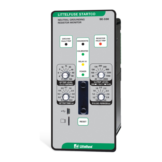
GROUND
FAULT
TRIP
DIAGNOSTIC
CALIBRATED
RELAY K1
15
10
20
8
40
POWER
6
60
4
80
2
100
GF TRIP LEVEL
(% CT RATING)
0.5 0.7 1.0
CAL
0.4
2.0
0.3
3.0
0.2
5.0
0.1
10.0
GF TRIP TIME (s)
RESET
Copyright 2013 Littelfuse Startco
All rights reserved.
Fx: (306) 374-2245 www.littelfuse.com/relayscontrols
SE-330
RESISTOR
FAULT
TRIP
200
170
340
130
800
100
1200
60
1700
20
2000
V TRIP LEVEL
N
20 K
Ω
Ω
(
100 K
)
S5
V x 1
V x 5
N
N
1.8 2.0 2.2
1.6
2.4
1.4
2.6
1.2
2.8
1.0
3.0
PULSE PERIOD (s)
Advertisement
Table of Contents

Related Manuals for Littelfuse Startco SE-330


Summary of Contents for Littelfuse Startco SE-330
- Page 1 (% CT RATING) 100 K V x 1 V x 5 0.5 0.7 1.0 1.8 2.0 2.2 10.0 GF TRIP TIME (s) PULSE PERIOD (s) RESET Copyright 2013 Littelfuse Startco All rights reserved. Publication: SE-330-M Document: S95-C330-00000 Printed in Canada.
-
Page 2: Table Of Contents
2.1.5.4 Resistor-Fault-Trip Latch (S4) ..4 SE-330 Connection Diagram ........7 2.1.5.5 Sensing-Resistor Selection (S5) ..4 SE-330 Outline and Panel-Mounting Details ... 8 2.1.5.6 Frequency (S6) ......... 4 SE-330 Outline and Surface-Mounting Details ..9 2.1.5.7 Spare (S7) ........4 SE-IP65CVR-G Weatherproof Cover Outline .. -
Page 3: General
Furthermore, the transformer or generator neutral-to-ground voltage. The probability of an arc-flash incident is significantly components required to monitor an NGR are an SE-330, a reduced in a high-resistance-grounded system. 20- or 100-k ER-series sensing resistor, and a current NGR selection depends on system charging current and transformer (CT). -
Page 4: Operation
12 seconds and ground-fault current is less than upgrades and access to SE-330 measured parameters. 5% of the CT rating, the SE-330 will trip on resistor fault. If the resistor-fault circuit is tripped and the neutral voltage 2. O... -
Page 5: Pulse-Period Adjustment
ERIOD DJUSTMENT Pulse period is the cycle time of relay K1 when the SE-330 is configured for pulsing operation. Pulse period CALBIRATION PUSH BUTTON is adjustable from 1.0 to 3.0 seconds with a fixed duty cycle of 50%. For example, with the 1.0-s setting, relay K1 will alternately be energized for 0.5 seconds and de-... -
Page 6: Relay K1 Function (S1)
Set switch S2 to select the operating mode of trip relay : If the SE-330 is not calibrated and is supplied K1. In the non-fail-safe mode, relay K1 energizes and its from the load side of the breaker (non-fail-safe mode), contact closes when a trip occurs. -
Page 7: Trip Indication And Reset
When supply voltage is applied with switch S2 set to Software-Interrupt Trip (5 short): FAIL-SAFE, the SE-330 returns to its state prior to loss CPU reset was caused by a software interrupt. of supply voltage unless switch S3 or S4 is set to non- latching. -
Page 8: Analog Output
24-Vdc supply allows the analog output to be connected as a self-powered output. Power from an shown in Fig. 4. To panel mount the SE-330, insert it external supply is required for loop-powered operation. through the panel cutout and secure it with four 8-32 See Fig. -
Page 9: Se-330 Connection Diagram
5. SEE SECTION 3.4 FOR ISOLATED-RESISTOR SELF POWERED REMOTE CONNECTION. 4-20 mA RESET RESET OUTPUT 6. RELAY CONTACTS SHOWN WITH SE-330 PULSE DE-ENERGIZED. PULSE ENABLE ENABLE 7. OPTIONAL N.C. K4 AVAILABLE. 8. LOOP-POWERED CONNECTION USES TERMINALS 19 AND 20 ONLY. -
Page 10: Se-330 Outline And Panel-Mounting Details
SIDE VIEW REAR VIEW NOTE 2 92.7 (3.65) 76.2 (0.32) (3.00) NOTES: 1. DIMENSIONS IN MILLIMETRES (INCHES). 2. SE-330 SHOWN WITHOUT SWITCH ACCESS COVER. R=4.8 (0.19) MAXIMUM 4.75 (0.187) DIA 4 LOCATIONS PANEL-MOUNT CUTOUT FIGURE 4. SE-330 Outline and Panel-Mounting Details. -
Page 11: Se-330 Outline And Surface-Mounting Details
3. ENSURE THAT RETAINERS ARE AGAINST MONITOR BODY AND TIGHTEN RETAINER SCREWS. REMOVAL 1. LOOSEN RETAINER SCREWS, SLIDE RETAINERS AWAY FROM MONITOR BODY AND TIGHTEN RETAINER SCREWS. BEZEL OUTLINE 2. PULL MONITOR FORWARD. ADAPTER PANEL OUTLINE MOUNTING DETAIL FIGURE 5. SE-330 Outline and Surface-Mounting Details. -
Page 12: Se-Ip65Cvr-G Weatherproof Cover Outline
Page 10 SE-330 Neutral-Grounding-Resistor Monitor Rev. 9-A-112913 TO PREVENT UNAUTHORIZED ENTRY: 1. USE WIRE SEAL THROUGH HOLES IN WEATHERPROOF COVER ASSEMBLY, OR 2. SECURE WITH THE PLASTIC THREAD FORMING SCREW SUPPLIED IN KIT. TOP VIEW SHOWN HOLE FOR WITH SEAL WIRE SEAL 127.0... - Page 13 Page 11 SE-330 Neutral-Grounding-Resistor Monitor Rev. 9-A-112913 INSTALL O-RING INTO GROOVE IN THE REAR OF WEATHERPROOF WINDOW INSERT MONITOR/RELAY THROUGH OPENING OF THE WEATHERPROOF WINDOW, UNTIL IT IS SECURELY NESTED TO THE BACK OF THE DARK GREY PVC PANEL. INSTALL O-RING INTO THE GROOVE IN THE REAR OF WEATHERPROOF WINDOW ASSEMBLY.
-
Page 14: Sensing Resistor
Sensing-resistor moisture-resistant terminal covers. Use an ER-5WP in terminal R and its connection to SE-330 terminal R, applications in which it might be exposed to moisture. including interposing terminal blocks, must remain dry. The ER-15KV, ER-25KV, and ER-35KV include moisture-resistant terminal covers. - Page 15 Page 13 SE-330 Neutral-Grounding-Resistor Monitor Rev. 9-A-112913 GASKET 120.4 120.4 (4.74) (4.74) ENCLOSURE - TOP VIEW COVER - INSIDE VIEW (COVER REMOVED) 82.5 (3.25) (0.38) M6 OR 0.25-20 120.4 (4.74) ENCLOSURE - TOP VIEW MOUNTING DETAIL 120.4 (4.74) NOTES: 1. DIMENSIONS IN MILLIMETRES (INCHES).
-
Page 16: Se-Mre-600 Moisture-Resistant Enclosure Outline 13 10 Se-Mre-600 With Installed Er-600Vc
Page 14 SE-330 Neutral-Grounding-Resistor Monitor Rev. 9-A-112913 NOTE 2 MOUNTING SCREW LOCATIONS NOTE 3 E R - 6 0 0 V C SENSI NG RES I STOR 2 0 K Ω 6 0 0 V AC M A X NOTE 2... -
Page 17: Er-5Kv Sensing Resistor
Page 15 SE-330 Neutral-Grounding-Resistor Monitor Rev. 9-A-112913 RATINGS: 381.0 2,500 Vac MAXIMUM VOLTAGE (15.00) 21.0 MAXIMUM CURRENT 125 mA RESISTANCE ..20 kΩ (0.83) ALTERNATE NEUTRAL CONNECTION .. -
Page 18: Er-5Wp Sensing Resistor
Page 16 SE-330 Neutral-Grounding-Resistor Monitor Rev. 9-A-112913 RATINGS: MAXIMUM VOLTAGE 2,500 Vac 381.0 MAXIMUM CURRENT 125 mA (15.00) RESISTANCE 21.0 ..20 kΩ CONTINUOUS THERMAL .. -
Page 19: Er-15Kv Sensing Resistor
Page 17 SE-330 Neutral-Grounding-Resistor Monitor Rev. 9-A-112913 422.0 RATINGS: (16.61) MAXIMUM VOLTAGE 8,400 Vac MAXIMUM CURRENT 84 mA RESISTANCE ..100 kΩ THERMAL C A U T I O N E R - 1 5 KV... -
Page 20: Er-25Kv Sensing Resistor
Page 18 SE-330 Neutral-Grounding-Resistor Monitor Rev. 9-A-112913 780.0 (30.70) RATINGS: MAXIMUM VOLTAGE 14,400 Vac C A U T I O N E R - 2 5 KV CAUTION MAXIMUM CURRENT 144 mA SE NS I NG R ES I ST OR 100 K Ω... -
Page 21: Er-35Kv Sensing Resistor
Page 19 SE-330 Neutral-Grounding-Resistor Monitor Rev. 9-A-112913 RATINGS: 22,000 Vac MAXIMUM VOLTAGE 220 mA MAXIMUM CURRENT RESISTANCE ..100 kΩ 1000.0 THERMAL 22,000 Vac ..1 MINUTE ON, (39.40) -
Page 22: Ground-Fault Ct
CT-primary current injection testing is recommended to verify trip levels below 5% of the CT-primary rating. See Section 9.4. Littelfuse Startco sensitive current sensors are designed for use at low levels and respond linearly to 2% current rating. : The current-transformer insulation class is of no... -
Page 23: Efct-1 Ground-Fault Current Sensor
Page 21 SE-330 Neutral-Grounding-Resistor Monitor Rev. 9-A-112913 NOTES: 1. DIMENSIONS IN MILLIMETRES (INCHES). 2. MOUNTING SCREWS: M4 OR 8-32. 3. PRESS MOUNTING FEET IN PLACE USING INSTALLATION TOOL PROVIDED. 4. RoHS COMPLIANT. 5. EN 60044-1 COMPLIANT. 121.0 121.0 (4.76) (4.76) 20.5... -
Page 24: Se-Cs30-70 Ground-Fault Current Sensor
Page 22 SE-330 Neutral-Grounding-Resistor Monitor Rev. 9-A-112913 121.0 121.0 (4.76) (4.76) 20.5 80.0 (3.15) (0.81) NOTE 3 M5 SCREWS MOUNTING DETAIL 25.0 30.0 (0.98) (1.18) S E - C S 3 0 - 7 0 C U R R E N T S E N S O R LR 53428 Ø... -
Page 25: Efct-26 And Se-Cs30-26 Ground-Fault Current Sensors
Page 23 SE-330 Neutral-Grounding-Resistor Monitor Rev. 9-A-112913 68.0 68.0 (2.68) (2.68) 17.0 34.0 (0.67) (1.34) M4 OR 8-32 TAP M5 SCREWS MOUNTING DETAIL 25.0 26.5 (0.98) (1.04) S E - C S 3 0 - 2 6 C U R R E N T S E N S O R LR 53428 4.0 (0.16) Ø... -
Page 26: Isolated Ground Connection
An isolated ground bed can prevent a ground potential rise (GPR) from being transferred to remote equipment. NEUTRAL If the G terminals on the sensing resistor and the SE-330 are connected to an isolated ground, the SE-330 will be ER-SERIES exposed to the GPR. -
Page 27: Pulsing Connection
4.1.3 F IRMWARE PGRADE which is designed for use with firmware-upgrade and The local port can be used to upgrade the SE-330 system-monitoring software running on a PC. firmware. Upgrade procedure: The RS-232 port is non-isolated and operates as a 1) Remove supply voltage. -
Page 28: Troubleshooting
See Section 9.2 for sensing-resistor tests. Repeat the calibration procedure after the open or shorted condition has been corrected. The SE-330 was tripped by a signal from network communications. Remote Trip DIAGNOSTIC LED flash code = L-S-S-L…* Press RESET to clear the trip. -
Page 29: Technical Specifications
Page 27 SE-330 Neutral-Grounding-Resistor Monitor Rev. 9-A-112913 1-A Input ......< 0.05 6. T ECHNICAL PECIFICATIONS EFCT Input ......< 10 6.1 SE-330 Supply Thermal Withstand: Option 0 ......... 30 VA, 120 to 240 Vac 1-A and 5-A Input: (+10, -45%) 50/60 Hz;... -
Page 30: Sensing Resistors
Page 28 SE-330 Neutral-Grounding-Resistor Monitor Rev. 9-A-112913 Auto-reset time ......2.8 s maximum 6.2 S ENSING ESISTORS ER-600VC: 4–20-mA Analog Output: Maximum Voltage ....600 Vac Type .......... Self Powered and Maximum Current ....30 mA Loop Powered Resistance ......20 k... -
Page 31: Current Sensors
2 48 Vdc Supplemental Specifications: Trip Level Accuracy: Please refer to the SE-330 Product Change Notice OTE: ≤ 1 A ..... 1% of CT-Primary Rating (PCN) document for updated ordering information and new > 1 A ..... 3% of CT-Primary Rating revision details, available at www.littelfuse.com/se-330. -
Page 32: Warranty
Littelfuse Startco will (at Littelfuse Startco’s option) repair, replace, or refund the original purchase price of an SE-330 that is determined by Littelfuse Startco to be defective if it is returned to the factory, freight prepaid, within the warranty period. This warranty does not apply... -
Page 33: Test Procedures
SE-330 resistance- measuring circuit. Applying the test voltage to the R and G terminals will OTE: damage the SE-330 and the ER sensing resistor. The V TRIP LEVEL is the trip voltage at terminal N, not terminal R. Procedure: ... -
Page 34: Ground-Fault Performance Test
The connection of the current-transformer secondary to the SE-330 is not polarity sensitive. c) Verify that the system is correctly grounded and that alternate ground paths do not exist that bypass the current transformer. -
Page 35: Ground-Fault-Test Circuits
Page 33 SE-330 Neutral-Grounding-Resistor Monitor Rev. 9-A-112913 TABLE 4. G ROUND AULT ECORD a) USING SE-400 ESULTS NEUTRAL TO SE-330 TO SENSING RESISTOR TERMINAL N SE-400 RMT1 REMOTE INPUT RMT2 b) USING SE-100T NEUTRAL TO SE-330 TO SENSING RESISTOR TERMINAL N 0.65 A... - Page 36 Page 34 SE-330 Neutral-Grounding-Resistor Monitor Rev. 9-A-112913 This page intentionally left blank.
Need help?
Do you have a question about the SE-330 and is the answer not in the manual?
Questions and answers