
Related Manuals for Littelfuse Startco SE-135


Summary of Contents for Littelfuse Startco SE-135
- Page 1 SE-135 MANUAL GROUND-FAULT GROUND-CHECK MONITOR REVISION 3-D-090816 Copyright © 2016 by Littelfuse Startco. All rights reserved. Document Number: PM-1315-EN Printed in Canada.
- Page 2 Page i SE-135 Ground-Fault Ground-Check Monitor Rev. 3-D-090816 This page intentionally left blank...
-
Page 3: Table Of Contents
IGURE General ..............1 SE-135 Typical Application ........4 Operation ............. 1 SE-135 Outline and Panel-Mounting Details ..5 2.1 Ground-Fault Circuit ..........1 SE-134-SMA Surface Mount Adapter and 2.1.1 GF Trip Time Setting ......... 1 SE-135 Surface-Mounting Details ......6 SE-IP65CVR-G Weatherproof Cover Outline .. - Page 4 Page iii SE-135 Ground-Fault Ground-Check Monitor Rev. 3-D-090816 This page intentionally left blank.
-
Page 5: General
The SE-135 meets the IEEE surge- characteristic with 11 settings from 0.1 to 2.5 seconds. withstand-capability tests (oscillatory and fast transient) Time-coordinated ground-fault protection requires the trip for protective relays and relay systems. -
Page 6: Reset
On start-up SE-MON-GFGC scans the network for inoperative when remote-reset terminals 9 and 10 are SE-135 units and displays them in a list. Select one from connected. See Section 4.5. the list and click “Edit” to change the IP address, subnet mask, or description. -
Page 7: Indication
SE-135 to trip. Return the is internally connected to terminal 4. For these units an SE-135 to the factory if a reset does not clear the trip. external terminal-3-to-terminal-4 connection is not Induced ac current in the ground-check loop can cause required, nor is it necessary to remove the terminal-3 the LED to flicker. -
Page 8: Parallel-Path Isolation
SE-135 Ground-Fault Ground-Check Monitor Rev. 3-D-090816 the monitored ground wire. See Figs. 10 and 11. See SE-135 terminals 26 and 27 and the red ground-fault indicator to terminals 19 and 21. For remote reset, Technical Note GC-10 “Parallel Path Isolator” at connect the normally open push-button switch across www.littelfuse.com/relayscontrols, or contact Littelfuse... -
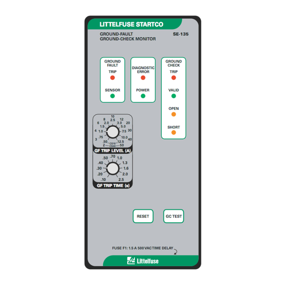
Page 9: Se-135 Outline And Panel-Mounting Details
Page 5 SE-135 Ground-Fault Ground-Check Monitor Rev. 3-D-090816 FIGURE 2. SE-135 Outline and Panel-Mounting Details. -
Page 10: Se-134-Sma Surface Mount Adapter And Se-135 Surface-Mounting Details
Page 6 SE-135 Ground-Fault Ground-Check Monitor Rev. 3-D-090816 FIGURE 3. SE-134-SMA Surface Mount Adapter and SE-135 Surface-Mounting Details. -
Page 11: Se-Ip65Cvr-G Weatherproof Cover Outline
Page 7 SE-135 Ground-Fault Ground-Check Monitor Rev. 3-D-090816 FIGURE 4. SE-IP65CVR-G Weatherproof Cover Outline. -
Page 12: Se-Ip65Cvr-G Weatherproof Cover Installation
Page 8 SE-135 Ground-Fault Ground-Check Monitor Rev. 3-D-090816 FIGURE 5. SE-IP65CVR-G Weatherproof Cover Installation. -
Page 13: Se-Ip65Cvr-G Weatherproof Cover Installation 8 6 Se-Cs10 And Se-Cs40 Current Sensors
Page 9 SE-135 Ground-Fault Ground-Check Monitor Rev. 3-D-090816 FIGURE 6. SE-CS10 and SE-CS40 Current Sensors. -
Page 14: Se-Ta12A And Se-Ta12A-Wl Termination Assemblies
Page 10 SE-135 Ground-Fault Ground-Check Monitor Rev. 3-D-090816 FIGURE 7. SE-TA12A and SE-TA12A-WL Termination Assemblies. -
Page 15: Se-Ta12Asf-Wl Small-Format-Wire-Lead Termination Assembly
Page 11 SE-135 Ground-Fault Ground-Check Monitor Rev. 3-D-090816 FIGURE 8. SE-TA12ASF-WL Small-Format-Wire-Lead Termination Assembly. FIGURE 9. RK-132 Remote Indication and Reset Kit. -
Page 16: Ppi-600V Parallel-Path Isolator
Page 12 SE-135 Ground-Fault Ground-Check Monitor Rev. 3-D-090816 FIGURE 10. PPI-600V Parallel-Path Isolator. -
Page 17: Ppi-600V Typical Installation
Page 13 SE-135 Ground-Fault Ground-Check Monitor Rev. 3-D-090816 FIGURE 11. PPI-600V Typical Installation. -
Page 18: Se-135 With Ferrites Installed
Page 14 SE-135 Ground-Fault Ground-Check Monitor Rev. 3-D-090816 FIGURE 12. SE-135 with Ferrites Installed. FIGURE 13. Current Sensor Shield Connection. -
Page 19: Technical Specifications
Page 15 SE-135 Ground-Fault Ground-Check Monitor Rev. 3-D-090816 5. T Trip Mode ......Latching or Non-Latching ECHNICAL PECIFICATIONS 5.1 SE-135 Trip Relay: Supply: CSA/UL Contact Rating ..8 A Resistive 250 Vac, Option 0 ......... 25 VA, 120-240 Vac 5 A 30 Vdc, (+10, -45%), 50-400 Hz;... -
Page 20: Current Sensors
Page 16 SE-135 Ground-Fault Ground-Check Monitor Rev. 3-D-090816 IP Rating ........IP40 when panel- Certification ......CSA Canada and USA mounted, IP20 otherwise Surge Withstand ....... ANSI/IEEE 37.90.1-2002 UL Listed (Oscillatory and Fast Transient) EMC Tests: Australia Verification tested in accordance with EN 60255-26:2009. -
Page 21: Termination Assemblies
Wire Leads ......18 AWG (0.82 mm 300 mm (11.8”) NOTES: Dimensions ......58.8 x 19 x 12.7 mm (2.32 x 0.75 x 0.5”) When connected to an SE-135. Shipping Weight ....45 g (0.1 lb) 5.3 T ERMINATION SSEMBLIES SE-TA12A: Certification ...... -
Page 22: Ordering Information
Littelfuse Startco will (at Littelfuse Startco’s option) Leads repair, replace, or refund the original purchase price of an SE-TA12ASF-WL ....12-W Small-Format SE-135 that is determined by Littelfuse Startco to be Termination Assembly defective if it is returned to the factory, freight prepaid, with Wire Leads within the warranty period. -
Page 23: Test Procedures
Page 19 SE-135 Ground-Fault Ground-Check Monitor Rev. 3-D-090816 8. T Short the ground-check loop by connecting G to GC. ROCEDURES The monitor will trip. The trip contacts (terminals 22-23 8.1 G ROUND- HECK ESTS and 24-25) and the ground-check indication contacts 8.1.1 L... -
Page 24: Ground-Fault Performance Test
To simulate ground-fault current, use CT-primary current injection. Fig. 14 shows a test circuit using Littelfuse Startco Ground- Fault-Relay Test Units. The SE-400 has a programmable output of 0.5 to 9.9 A for a duration of 0.1 to 9.9 seconds. -
Page 25: Trip Relay Maximum Switching Capacity
Page 21 SE-135 Ground-Fault Ground-Check Monitor Rev. 3-D-090816 FIGURE 14. Trip Relay Maximum Switching Capacity. FIGURE 15. Remote-Indication Relays GC and GF Maximum Switching Capacity. -
Page 26: Ground-Fault-Test Circuit
Page 22 SE-135 Ground-Fault Ground-Check Monitor Rev. 3-D-090816 FIGURE 16. Ground-Fault-Test Circuit. FIGURE 17. Termination-Assembly-Test Circuits. -
Page 27: Appendix A Se-135 Revision History
Page 23 SE-135 Ground-Fault Ground-Check Monitor Rev. 3-D-090816 APPENDIX A SE-135 REVISION HISTORY MANUAL MANUAL PRODUCT REVISION RELEASE DATE REVISION (REVISION NUMBER ON PRODUCT LABEL) September 8, 2016 3-D-090816 October 3, 2014 3-C-100314 November 12, 2013 3-B-111213 May 14, 2013... - Page 28 Page 24 SE-135 Ground-Fault Ground-Check Monitor Rev. 3-D-090816 This page intentionally left blank.
- Page 29 Mouser Electronics Authorized Distributor Click to View Pricing, Inventory, Delivery & Lifecycle Information: Littelfuse SE-134-SMA...
Need help?
Do you have a question about the SE-135 and is the answer not in the manual?
Questions and answers