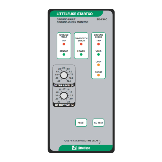
Summary of Contents for Littelfuse Startco SE-134C
- Page 1 SE-134C MANUAL GROUND-FAULT GROUND-CHECK MONITOR REVISION 7-D-090816 Copyright © 2016 by Littelfuse Startco. All rights reserved. Document Number: PM-1310-EN Printed in Canada.
- Page 2 Page i SE-134C Ground-Fault Ground-Check Monitor Rev. 7-D-090816 This page intentionally left blank.
-
Page 3: Table Of Contents
IGURE General ..............1 SE-134C Typical Application ....... 4 Operation ............. 1 SE-134C Outline and Panel-Mounting Details ..5 2.1 Ground-Fault Circuit ..........1 SE-134-SMA Surface Mount Adapter and 2.1.1 GF Trip Time Setting ......... 1 SE-134C Surface-Mounting Details ..... 6 SE-IP65CVR-G Weatherproof Cover Outline .. - Page 4 Page iii SE-134C Ground-Fault Ground-Check Monitor Rev. 7-D-090816 This page intentionally left blank.
-
Page 5: General
X0 ordering option. See Technical Note GC-09, available specifications apply over an industrial temperature range at www.littelfuse.com/relayscontrols. at high humidity. The SE-134C meets the IEEE surge- 2. O PERATION withstand-capability tests (oscillatory and fast transient) for protective relays and relay systems. -
Page 6: Reset
SE-134C to trip. Return the control circuit. With no connection between terminals 12 SE-134C to the factory if a reset does not clear the trip. and 13, the SE-134C trip relay operates in the fail-safe Induced ac current in the ground-check loop can cause mode. -
Page 7: Monitor
Outline and panel-cutout dimensions for the SE-134C The optional RK-132 Remote Kit is shown in Fig. 9. are shown in Fig. 2. To panel mount the SE-134C, insert Connect terminals of the green ground-check indicator to it through the panel cutout and secure it with the four SE-134C terminals 26 and 27 and the red ground-fault supplied 8-32 locknuts and flat washers. -
Page 8: Se-134C Typical Application
Page 4 SE-134C Ground-Fault Ground-Check Monitor Rev. 7-D-090816 FIGURE 1. SE-134C Typical Application. -
Page 9: Se-134C Outline And Panel-Mounting Details
Page 5 SE-134C Ground-Fault Ground-Check Monitor Rev. 7-D-090816 FIGURE 2. SE-134C Outline and Panel-Mounting Details. -
Page 10: Se-134-Sma Surface Mount Adapter And Se-134C Surface-Mounting Details
Page 6 SE-134C Ground-Fault Ground-Check Monitor Rev. 7-D-090816 FIGURE 3. SE-134-SMA Surface Mount Adapter and SE-134C Surface-Mounting Details. -
Page 11: Se-Ip65Cvr-G Weatherproof Cover Outline
Page 7 SE-134C Ground-Fault Ground-Check Monitor Rev. 7-D-090816 FIGURE 4. SE-IP65CVR-G Weatherproof Cover Outline. -
Page 12: Se-Ip65Cvr-G Weatherproof Cover Installation
Page 8 SE-134C Ground-Fault Ground-Check Monitor Rev. 7-D-090816 FIGURE 5. SE-IP65CVR-G Weatherproof Cover Installation. -
Page 13: Se-Cs10 Current Sensors
Page 9 SE-134C Ground-Fault Ground-Check Monitor Rev. 7-D-090816 FIGURE 6. SE-CS10 Current Sensors. -
Page 14: Se-Ta6A And Se-Ta6A-Wl Termination Assemblies
Page 10 SE-134C Ground-Fault Ground-Check Monitor Rev. 7-D-090816 FIGURE 7. SE-TA6A and SE-TA6A-WL Termination Assemblies. -
Page 15: Se-Ta6Asf-Wl Small-Format-Wire-Lead Termination Assembly
Page 11 SE-134C Ground-Fault Ground-Check Monitor Rev. 7-D-090816 FIGURE 8. SE-TA6ASF-WL Small-Format-Wire-Lead Termination Assembly. FIGURE 9. RK-132 Remote Indication and Reset Kit. -
Page 16: Ppi-600V Parallel-Path Isolator
Page 12 SE-134C Ground-Fault Ground-Check Monitor Rev. 7-D-090816 FIGURE 10. PPI-600V Parallel-Path Isolator. -
Page 17: Ppi-600V Typical Installation
Page 13 SE-134C Ground-Fault Ground-Check Monitor Rev. 7-D-090816 FIGURE 11. PPI-600V Typical Installation. -
Page 18: Se-134C With Ferrites Installed
Page 14 SE-134C Ground-Fault Ground-Check Monitor Rev. 7-D-090816 FIGURE 12. SE-134C with Ferrites Installed. FIGURE 13. Current Sensor Shield Connection. -
Page 19: Technical Specifications
Page 15 SE-134C Ground-Fault Ground-Check Monitor Rev. 7-D-090816 5. T Supplemental Contact Ratings: ECHNICAL PECIFICATIONS Make/Carry (0.2 s) ... 30 A 5.1 SE-134C Break dc ......75 W Resistive, Supply: 35 W Inductive (L/R < 0.04) Option 0 ......... 25 VA, 120-240 Vac Break ac ...... - Page 20 Page 16 SE-134C Ground-Fault Ground-Check Monitor Rev. 7-D-090816 EMC Tests: Certification ......... CSA, Canada and USA Verification tested in accordance with EN 60255-26:2009. Radiated and Conducted UL Listed Emissions ......CISPR 22:2008-09 Class A Current Harmonics and Australia Voltage Fluctuations ... IEC 61000-3-2...
-
Page 21: Current Sensors
Compliance ....... IEC 60044-1 Dimensions ......58.8 x 19 x 12.7 mm RoHS Pending (2.32 x 0.75 x 0.5”) NOTES: Shipping Weight ....45 g (0.1 lb) When connected to an SE-134C. 5.3 T Certification ......... CSA, Canada and USA ERMINATION SSEMBLIES SE-TA6A: Characteristic ...... -
Page 22: Warranty
TRIP and the OPEN LED’s will be on. SE-134C that is determined by Littelfuse Startco to be Reconnect the ground-check loop. The monitor will defective if it is returned to the factory, freight prepaid, reset. -
Page 23: Se-Ta6A-Series Termination Assembly Tests
To simulate ground-fault current, use CT-primary current injection. Fig. 14 shows a test circuit using Littelfuse Startco Ground- Retain this record for the authority having jurisdiction. Fault-Relay Test Units. The SE-400 has a... -
Page 24: Trip Relay Maximum Switching Capacity
Page 20 SE-134C Ground-Fault Ground-Check Monitor Rev. 7-D-090816 FIGURE 14. Trip Relay Maximum Switching Capacity. FIGURE 15. Remote-Indication Relays GC and GF Maximum Switching Capacity. -
Page 25: Ground-Fault-Test Circuit
Page 21 SE-134C Ground-Fault Ground-Check Monitor Rev. 7-D-090816 FIGURE 16. Ground-Fault-Test Circuit. FIGURE 17. Termination-Assembly-Test Circuits. -
Page 26: Appendix A Se-134C Revision History
Page 22 SE-134C Ground-Fault Ground-Check Monitor Rev. 7-D-090816 APPENDIX A SE-134C REVISION HISTORY MANUAL MANUAL PRODUCT REVISION RELEASE DATE REVISION (REVISION NUMBER ON PRODUCT LABEL) September 8, 2016 7-D-090816 October 1, 2014 7-C-100114 August 20, 2013 7-B-111213 May 6, 2013... - Page 27 Mouser Electronics Authorized Distributor Click to View Pricing, Inventory, Delivery & Lifecycle Information: Littelfuse SE-4-SMA SE-134-EMC-00...


Need help?
Do you have a question about the SE-134C and is the answer not in the manual?
Questions and answers